Back to Journals » Journal of Pain Research » Volume 15
MRI and Anatomical Determinants Affecting Neuroforaminal Stenosis Evaluation: A Descriptive Observational Study
Authors Wahezi SE, Hillery T, Przkora R, Lubenow T ![]() , Deer T
, Deer T ![]() , Kim C, Sayed D
, Kim C, Sayed D ![]() , Krystal J, Kinon M, Sitapara K, Nguyen K, Wong D, Sperling K
, Krystal J, Kinon M, Sitapara K, Nguyen K, Wong D, Sperling K
Received 17 February 2022
Accepted for publication 10 May 2022
Published 24 May 2022 Volume 2022:15 Pages 1515—1526
DOI https://doi.org/10.2147/JPR.S360847
Checked for plagiarism Yes
Review by Single anonymous peer review
Peer reviewer comments 2
Editor who approved publication: Professor Michael Überall
Sayed E Wahezi,1 Terence Hillery,2 Rene Przkora,3 Tim Lubenow,4 Tim Deer,5 Chong Kim,2 Dawood Sayed,6 Jonathan Krystal,7 Merritt Kinon,8 Kishan Sitapara,7 Kim Nguyen,7 Daniel Wong,7 Karen Sperling7
1Montefiore Multidisciplinary Pain Program, Montefiore Medical Center, Bronx, NY, USA; 2The MetroHealth System, Cleveland, OH, USA; 3Department of Anesthesiology, University of Florida College of Medicine, Gainesville, FL, USA; 4Department of Anesthesiology, Rush University Medical Center, Chicago, IL, USA; 5Department of Anesthesiology, West Virginia University, Morgantown, WV, USA; 6The University of Kansas Health System, Kansas City, KS, USA; 7Montefiore Medical Center, Bronx, NY, USA; 8Department of Neurosurgery, USA Brain and Spine Institute, Westchester Medical Center Health Network, New York Medical College, Valhalla, NY, USA
Correspondence: Sayed E Wahezi, Montefiore Health System, Montefiore Multidisciplinary Pain Program, 1250 Waters Place, Tower #2, Bronx, NY, 10461, USA, Tel +1 929-263-3852, Fax +1 929-263-3950, Email [email protected]
Purpose: Neuroforaminal stenosis (NFS), a narrowing of the intervertebral foramen, is a cause of disability in the aging population. Formal magnetic resonance imaging (MRI) classification of NSF has been developed recently and contradictory findings have been reported. This study aims to assess whether in-plane, anatomically conformed two-dimensional (2D) views of the neuroforamen characterize NFS more accurately than traditional axial, coronal, and sagittal views in healthy individuals with and without simulated scoliosis.
Patients and methods: This observational study was approved by the designated institutional review board at our academic tertiary care center. Four volunteers underwent lumbar spine MRI twice, once in the supine position and once with intentionally introduced hip tilt. The latter resulted in lumbar curvature mimicking positioning errors approximating degenerative lumbar scoliosis. Anatomically oriented cuts such as axial with endplate correction and coronally obliqued parasagittals, also called coronal obliques, were performed. Standard sagittal and axial views were also performed in both the supine and rotated groups.
Results: Coronal oblique and anatomically oriented axial views demonstrated the highest correlation with true neuroforaminal caliber. Deviation from anatomical congruence resulted in false measurements of neuroforaminal size. The hip-tilt studies produced MR that were less favorable to characterization of the caliber of neuroforamina. Coronal sections demonstrated reliability only when performed at the mid-pedicular lines. Standard axial views were reliable only when taken at the upper one-third of the neuroforamen. Coronal oblique views demonstrated superiority when evaluating consecutive neuroforamen on one image compared to non-obliqued parasagittal slices.
Conclusion: To minimize error in neuroforaminal analysis, imaging specialists should perform anatomically oriented cuts to conform to individual patient anatomy. When this cannot be performed due to a patient’s spine rotation or position, the MRI reader should view oblique, axial, and coronal images simultaneously and dynamically for proper foraminal characterization.
Keywords: foraminal stenosis, lumbar vertebrae, magnetic resonance imaging, neural foramen, scoliosis
Introduction
Neuroforaminal stenosis (NFS), a narrowing of the intervertebral foramen, is recognized as a growing cause of disability in the aging population.1 Magnetic resonance imaging (MRI) is the preferred imaging technique to diagnose NFS.2 In 2010, Lee et al published an MRI grading system for lumbar NFS.3 The Lee grade is based on the classic lumbar MRI protocol, with grading performed in a true parasagittal view. However, when Lee grading and intraoperative neuroforamen measurements have been compared, the reliability of Lee grading has been shown to depend on the level of the neuroforamen.4 It has been suggested that the wider transverse pedicle angles in the lower lumbar spine, as well as degenerative scoliotic changes, may account for the lower reliability of the Lee classification observed in the lower lumbar spine.
In part to address this perceived deficiency, other NFS classifications have been proposed, including a computed tomography-based classification5 and an updated version of Lee grading, which uses compressed SENSE-accelerated three-dimensional (3D) lumbar MRI sequences. The latter has demonstrated strong interobserver reliability in some studies, although 3D MRI is not widely used in clinical settings.6 The primary advantage of 3D MRI in this context is the ability to visualize in-plane anatomical views of the neuroforamen throughout the lumbar spine. This study aims to characterize whether in-plane anatomically conformed two-dimensional (2D) views of the neuroforamen characterize NFS more accurately than traditional axial, coronal, and sagittal views in healthy individuals with and without simulated scoliosis.
Methods
The study was approved by the Montefiore Health System Institutional Review Board (IRB# 201910849) and complies with the Declaration of Helsinki. Informed consent was obtained by all study participants prior to study commencement. Four volunteers underwent lumbar spine MRI twice. In the first study, the individuals carefully assumed the supine position, which is standard for MRI positioning. In the second study, the individuals intentionally introduced hip tilt and rotation, resulting in lumbar spine side-bending. This was done to mimic patient positioning errors and to approximate slight lumbar scoliosis. The radiology technicians performing the study were instructed to orient standard axial cuts to bisect the intervertebral discs and standard parasagittal cuts to bisect the pedicles. The technicians also obtained coronal obliques, or coronally obliqued parasagittal views, to align with the taper of the lumbar pedicles. In the rotated group, the technicians obtained axial views parallel to the endplate most proximal to the neuroforamen (ie, the inferior endplate of the cranial vertebral body). The images were analyzed to determine which neuroforamina could be well-characterized with the resultant MRIs.
Description of Normal Anatomy
Central Canal
The central canal has osseous borders within the vertebral body at the pedicle level. At the level of the disc, it also has a region of partial osseous borders. The anterior border of the central canal is the posterior vertebral body, the lateral border is the medial periosteum of the pedicles, and the posterior border is the lamina (Figure 1A and B). At the disc level, the central canal is bordered anteriorly by the posterior annulus and posterolaterally by the superior aspect of the superior articulating process (SAP); posteriorly it is bordered by the ligamentum flavum (Figure 2A and B). At the pedicle level, the central canal contains the thecal sac and cauda equina with all lumbar and sacral nerves, including the index vertebral body. At the disc level, the contents of the thecal sac are all lumbosacral nerves except the nerve of the associated vertebral body.
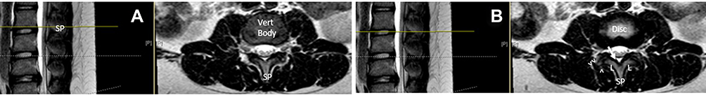 |
Figure 1 (A and B) The anterior border of the central canal is the posterior vertebral body at the vertebral body level (A). At the mid disc level (B) the lateral border of the central canal is the medial periosteum of the pedicles (arrow), and the posterior border is the lamina. The spinous process (SP) and lamina (L) are the posterior border of the central canal. The superior aspect of the superior articulating process (double arrow heads) is the posterior border of the neural canal The inferior articulating process (single arrow head) does not communicate with the neural foramen. |
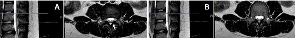 |
Figure 2 At the lower disc level (A), the central canal is bordered anteriorly by the posterior annulus and posterolaterally by the superior articulating process (SAP) (double arrow heads). Posteriorly, the central canal is bordered by the ligamentum flavum (arrow). The lateral border of the central canal is the superior and inferior articulating process (double and single arrowheads, respectively) which creates the facet joint. (B) demonstrates pedicular architecture at the superior endplate (P) and lack of neural foramen. |
Neuroforaminal Canal
The neuroforaminal canal is the defined space bordered superiorly by the inferior aspect of the superior pedicle; inferiorly by the superior aspect of the inferior pedicle; anterior-superiorly by the posterolateral vertebral body and anterior-inferiorly by disc; posteriorly by the anterior borders of the SAP and inferior articulating process; and medially by the thecal sac (Figure 3). The spinal nerve within the lumbar foramen is named after the associated superior vertebral body. The associated neuroforamen, intervertebral disc, and facet are all similarly named. For example, the L4-L5 neuroforamen has an associated L4-L5 disc and L4-L5 facet; the nerve emanating from this region is the L4 spinal nerve. Coronal sections of adult lumbar spines, when assessed from cranial to caudal, become progressively wider as the transverse pedicle angle increases. Pedicle circumference and position is commensurate with this trend (Figure 4).
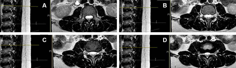 |
Figure 3 (A) demonstrates a parasagittal mid pedicular cut at the top of the vertebral body; axial cut image of the pedicle is seen on the right. Note the lack of a neural foramen at this level. (B) illustrates a parasagittal image directly below the pedicle (left) and a patent neural foramen (NF) on the right image. (C) (left) is a mid foraminal cut which defines the exiting spinal nerve (N) on the axial image to the right. (D) (bottom right) is a slice taken below the spinal nerve and just above the pedicle. Notice how the NF is narrow here compared to 3B or 3C. |
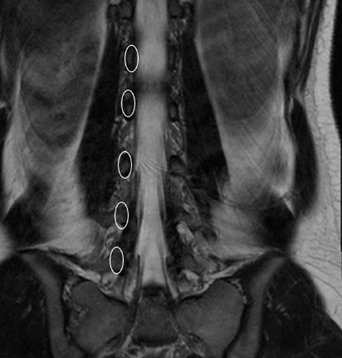 |
Figure 4 Coronal MRI slice of an adult normal lumbar spine. The left pedicles of L1-L5 have been circled here and demonstrate a natural oblique tapering. Notice the intertransverse distance between the pedicles becomes greater with the lower lumbar spine vertebrae. |
Procedure
In the first part of the study, four healthy individuals without spine pathology were enrolled and placed in an MRI scanner. All examinations were performed on a Siemens Magnetom® 3T MRI scanner (Siemens, Munich, Germany). All individuals were entered into the MRI scanner in the standard position, assuming a supine position with their shoulders and trunk square to the table (Figure 5). The MRI radiology technician oriented the cut lines by using vertical and horizontal slices of anatomical position without respect to anatomical curvature. Standard parasagittal cuts were taken in 2- to 4-mm slices (Figure 6). Standard axial views were obtained using 2- to 4-mm cuts through each disc level perpendicular to the standard sagittal cuts at each vertebral junction (Figure 7). We refer to this group as Straight Position/Standard Cuts (S-S). After the standard cuts were obtained, the individuals remained in position and coronal oblique views were obtained. Coronally obliqued sagittals, also called coronal obliques, are parasagittal views obliqued in the coronal plane to bisect the midpedicular locations of L1-L5. Coronal oblique slices, 2 to 3 mm, were obtained medial and lateral to this line (Figure 8). We refer to this group as Straight Position/Coronal Oblique (S-CO).
 |
Figure 5 A depiction of how individuals were entered into the MRI scanner in the standard position, assuming a supine position with their shoulders and trunk square to the table. |
 |
Figure 6 Standard parasagittal cuts were taken in 2- to 4-mm slices. (A) demonstrates coronal image with standard cut line (yellow line). (B) demonstrates parasagittal image respective to slice in (A). |
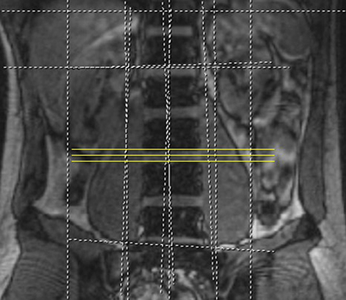 |
Figure 7 Standard axial views were obtained using 2- to 4-mm cuts through each disc level perpendicular to the standard sagittal cuts at each vertebral junction. |
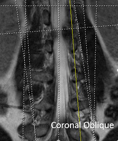 |
Figure 8 Coronally obliqued sagittals, also called coronal obliques, are parasagittal views obliqued in the coronal plane to bisect the midpedicular locations of L1-L5. Coronal oblique slices, 2 to 3 mm, were obtained medial and lateral to this line. |
After these images were obtained, the study participants were asked to perform a leg cross with hip hike and lower truncal rotation. This was done to produce anatomical congruence to rotational and sagittal scoliosis (Figure 9). Standard sagittal and axial cuts were again obtained (Figure 10) in what was named the Rotated Position/Standard Cuts (Rot-S) group. Coronal oblique views were obtained, with the goal of maximizing the number of midpedicle transections; axial sections were oriented parallel to the inferior endplate of the cranial vertebral body associated with the neuroforamen (Figure 11). Together, these views are referred to as the Rotated Position/Coronal Oblique and Parallel Endplate (Rot-COPE).
 |
Figure 9 The study participants were asked to perform a leg cross with hip hike and lower truncal rotation to produce anatomical congruence to rotational and sagittal scoliosis. |
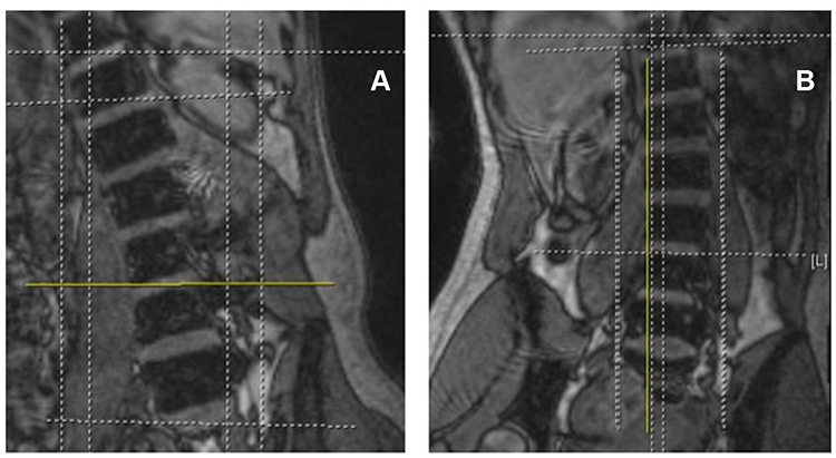 |
Figure 10 Rotation with Standard Cut Lines (Rot-S). (A) demonstrates coronal image with subject rotation and standard axial cut line (yellow line) without endplate adjustment. (B) is a coronal image with subject rotation and standard parasagittal cut line (yellow) without adjusting for position. |
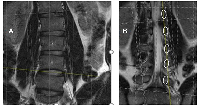 |
Figure 11 Rotated subect with coronal oblique and parallel endplate MRI slices (Rot-COPE). (A) represents a coronal image with axial cut line (yellow) through L45 with adjustment for endplate correction. (B) demonstrates a coronal image with parasagittal cut line (yellow) commensurate with upper pedicles only. |
Results
There was a significant difference in MRI characterization of the neuroforamina based on the individual’s body position, as well as the orientation of cut lines. These two variables were codependent in their ability to present a false positive or negative regarding spinal stenosis.
MRI cut lines taken at the top third, mid third, and bottom third of the neuroforamen on the axial image were able to modify the appearance of the canal diameter. At the upper third, where the spinal nerve resides, a cut demonstrated normal neuroforaminal caliber. However, when the cut was observed through the disc, at the lower third of the neuroforamen, the neuroforaminal canal diameter decreased by approximately 50% in all individuals when axial and parasagittal images were evaluated (Figure 12A and B). This follows the natural taper of the lumbar neuroforamen as the transverse pedicle angle increases caudally.
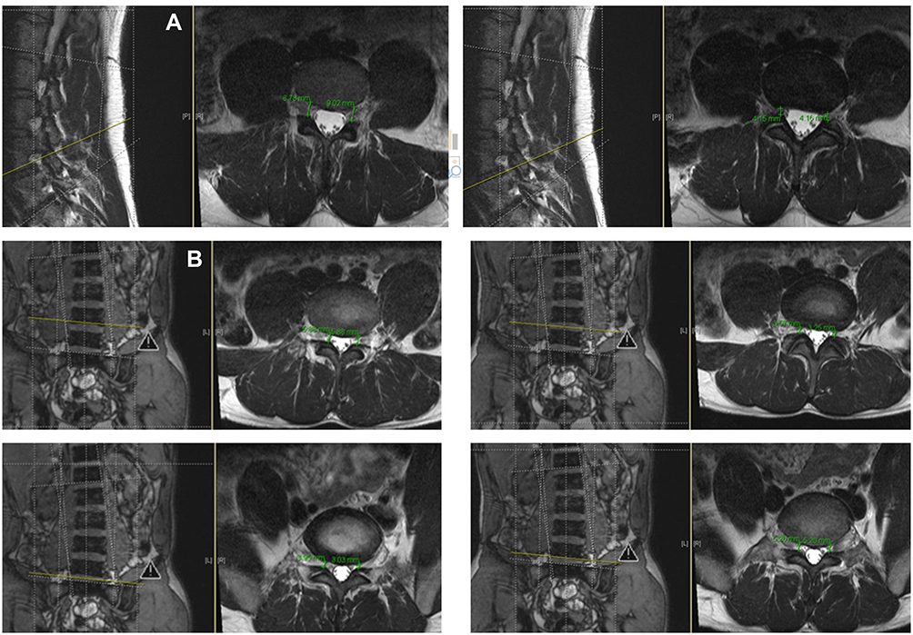 |
Figure 12 (A) Measurements of NF at and below the spinal nerve with parallel endplate (PE) slices. (B) Axial S-PE with measurements demonstrating NF caliber at and below the spinal nerve with parallel endplate (PE) slices. |
A comparison between the S-S and the S-COPE image cohorts was also performed. The S-COPE images universally demonstrated approximately 15% greater neuroforamen height than the S-S images. The key coronal oblique view, through the mid-body of the pedicles, allowed for visualization of all borders of the neuroforamina at multiple levels, allowing for improved characterization of the neuroforamen area and a more reliable comparison between neuroforamen. In standard sagittal views, cutlines did not consistently transect the midbody of the pedicles. All subsequent measurements and comparisons between neuroforamina were made without visualization of the borders of the true neuroforamen. A single parasagittal view, the basis of most NFS grading and classifications, was a less reliable technique for evaluating true neuroforaminal height (Figure 13).
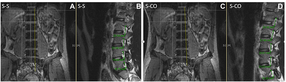 |
Figure 13 S-S vs S-CO demonstrating CO slices with less consistent NF caliber in this normal individual. 13A demonstrates false NF height (B) when standard coronal oblique line (yellow) is not commensurate with endplate taper (A). (D) demonstrates true NF height in all visualized NF when coronal oblique slice is performed (C). |
When the rotated cohort was evaluated with standard sagittal views, the pedicles were more unreliably transected, providing accurate images for neuroforaminal evaluation only where the sagittal cuts transected sequential pedicles (Figure 14). This cohort was also subjected to axial cuts parallel to the endplates (Rot-COPE). When this cut line, oriented parallel to the inferior endplate of the associated cranial vertebral body, was performed at the upper third of the neuroforamen, a consistent cranial/caudal view of the left and right neuroforamina was observed. However, when the standard horizontal axial cut was used to evaluate the same rotated individual, the axial line provided an asymmetric evaluation of the neuroforamina. Invariably, one axial cut imaged the caudal portion of one neuroforamen, whereas the contralateral side was imaged at the cranial portion. This produced a picture of NFS on the neuroforamen that was evaluated in the caudal portion of the neuroforamen when compared to a different portion of the contralateral neuroforamen, meaning side-to-side comparison at one level could not reliably be used to determine neuroforaminal patency or stenosis (Figure 15). When NFS is present, this effect is likely exaggerated. In one healthy individual, a 3° deviation from parallel to the endplate on an axial view produced a threefold decrease in the neuroforaminal width when measured in the anterior/posterior plane. Therefore, if care is not taken to read and understand coronal, axial, and sagittal sections simultaneously, a falsely positive or negative interpretation of stenosis may be made (Figure 16).
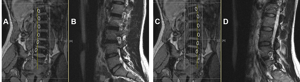 |
Figure 14 Rot-S demonstrating grossly inconsistent NF evaluation in sagittal sections. (A and C) demonstrates a standard coronal slice in a rotated patient in two different para-pedicular cuts. Note when the standard cut lines (yellow) do not align with the pedicles (white ovals) the sagittal representation of these cut line provides inaccurate NF evaluation through these pedicles (B and D). |
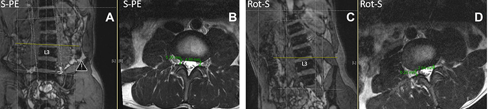 |
Figure 15 Coronal image of S-PE subject with axial slice at yellow line commensurate with endplate demonstrating symmetric caliber NF at the cut level (A and B). Same subject in rotated position. Coronal view (C) demonstrates axial slice (yellow line) in without adjusting for vertebral rotation, resulting in asymmetric NF with Rot-S axial view (D). |
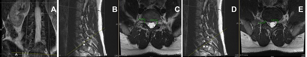 |
Figure 16 Individual with moderate L5S1(*) stenotic NF displayed with 3°axial cut from anatomical parallel (yellow line ^) (A–C). This small slice deviation from anatomical normal in mild stenosis creates a minimal NF change at the level of the spinal nerve(*) on axial evaluation, but an approximately 50% NF side-to-side caliber difference when the slice is taken below the spinal nerve (**) (D and E). |
A comparison of parasagittal and axial cuts was made in each group and the results were documented (Table 1). Reliability for all dimensions is shown in Table 2.
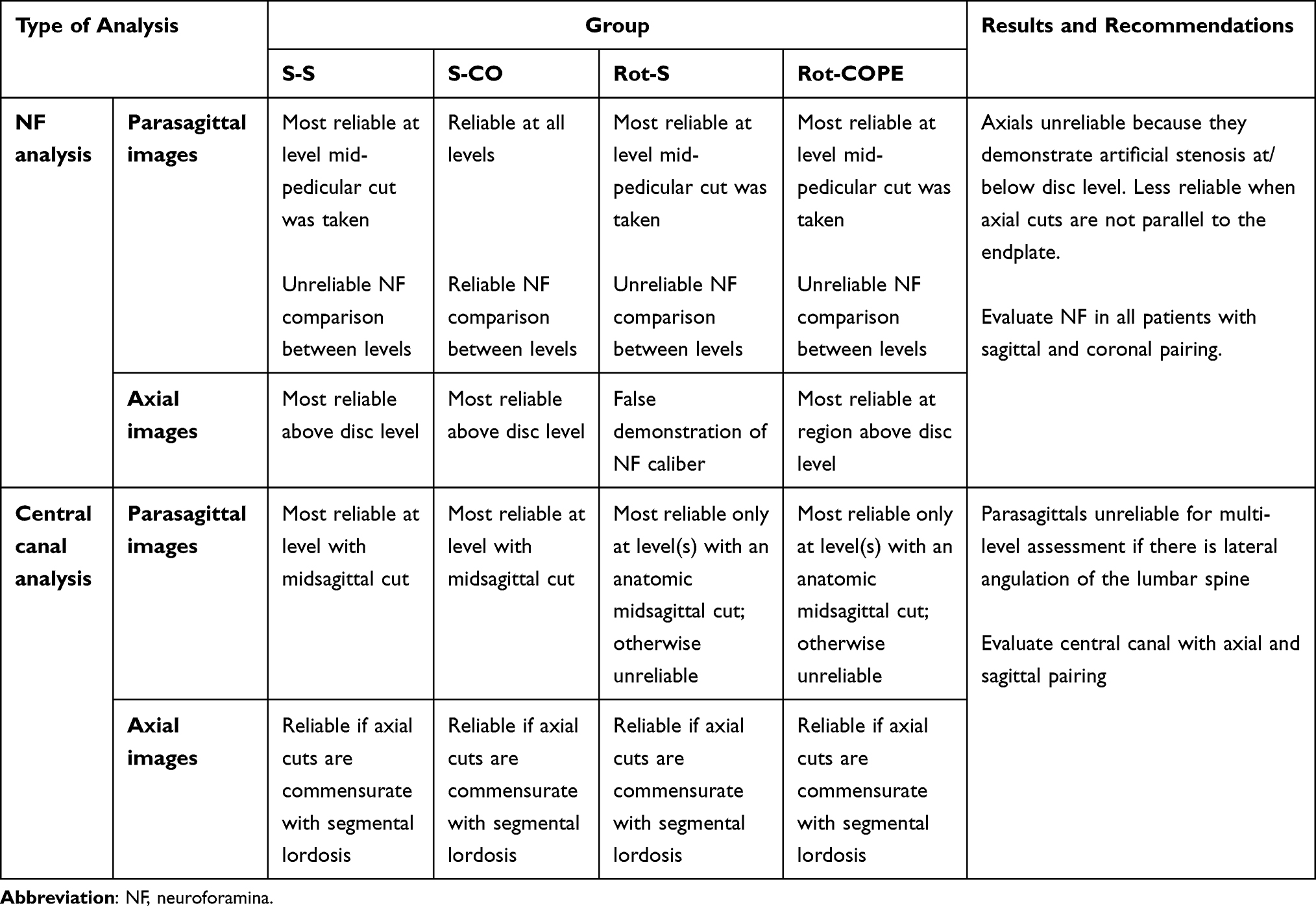 |
Table 1 Comparison of Parasagittal and Axial Cuts for Each Group |
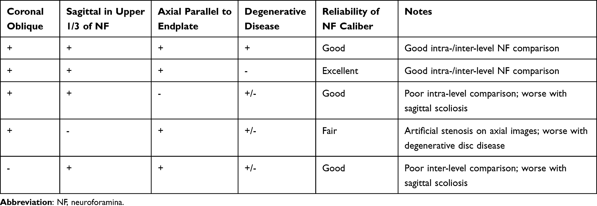 |
Table 2 Reliability of NFS based on MRI slices and degenerative disease |
Discussion
This study supports the authors’ position that proper diagnosis is achieved by assessing whether cut lines match pedicle and endplate architecture. The most accurate foraminal analysis is made when sagittal views are (1) oblique to pedicular taper, (2) sagittal cuts are at the mid pedicle level, and (3) axial sections are parallel to the inferior endplate of the neuroforamen of interest. Reliability is related to the number of conditions met and requires the clinician to evaluate all three dimensions for best assessment.
In the last decade, pain medicine physicians have increasingly performed percutaneous surgical procedures in addition to, and in lieu of, classic injection-based care practices. The field has progressed toward minimally invasive surgical implantation of devices and removal of tissue. This has created an increased need for pain physicians to understand and critically interpret advanced imaging to accurately diagnose patients and achieve favorable percutaneous surgical outcomes. The authors submit that improved MRI analysis will ultimately lead to better outcomes, which will reinforce the utility of these new devices used by pain physicians.
Lumbar spinal stenosis treatment devices have allowed pain physicians to forge into the percutaneous surgery space. These products have become popular due to the large burden of symptomatic patients with lumbar spinal stenosis and the lack of durable treatment options aside from open surgical decompression; epidural steroid injections and other conservative management techniques have not demonstrated durability. Older adult patients disproportionately suffer from lumbar spinal stenosis, and many are either not healthy enough to undergo open surgical decompression or reject them. For these patients, percutaneous surgeries are increasingly used to fill this gap.
The practitioner’s ability to accurately characterize stenosis may lead to surgical success or failure. Identification of NFS is difficult, in part because of the curvilinear anatomical distortion inherent in the linear sequencing used in 2D MRI. Diagnosis is even more challenging with comorbid degenerative scoliosis because the neuroforaminal space is more compromised, decreasing the margin for error in cutline placement. The prevalence of degenerative lumbar scoliosis in the older adult population is as high as 68%7 and the prevalence of degenerative lumbar stenosis is 20%.8 Therefore, scoliosis is often a cofactor in lumbar stenosis. This highlights the importance of properly characterizing NFS in the setting of scoliosis. In these cases, diagnosis and treatment planning may be challenging due to asymmetric evaluation of adjacent and contralateral foramen.
Limitations
This study represents the imaging characteristics of four healthy volunteers and has been generalized to describe patients with scoliotic curves. The authors acknowledge that this is a limitation of the project and that a larger-scale comparison of patients with normal and scoliotic spines is needed validate the findings here.
Conclusion
An accurate diagnosis of foraminal stenosis depends on accurate in-plane views of the neuroforamen. The importance of conforming these views with patient anatomy increases as degenerative disease worsens. The pain practitioner and spine surgeon should jointly evaluate several views when creating a surgical plan. Practitioners should consider requesting anatomically conforming MRI cutlines, such as coronally obliqued sagittal and endplate-adjusted axial views, if they suspect that stenosis is the underlying condition. We hope that coronal obliques become the standard in MRI imagery for non-scolotic spines, but we understand that this may be challenging to perform in the scoliotic spine without substantially adding to imaging or reading time. Therefore, the Pain practitioner should have the expertise to read images themselves until a more streamlined method of radiological analysis is developed.
Abbreviations
MRI, magnetic resonance imaging; NFS, neuroforaminal stenosis; SAP, superior articulating process; 2D, two-dimensional; 3D, three-dimensional.
Funding
This project was independently funded by Sayed Emal Wahezi, MD.
Disclosure
Dr Tim Lubenow reports grants and/or personal fees from Abbott, Medtronic, Boston Scientific, Nevro, Pentec Health, and Bond Pharmacy, outside the submitted work. Dr Tim Deer reports personal fees for consultant, research, and/or stock options from Abbott, Vertos, Flowonix, SpineThera, Saluda, Mainstay, Cornerloc, Ethos, SPR Therapeutics, SI Bone, Nevro, Medtronic, Boston Scientific, PainTeq, Tissue Tech, Spinal Simplicity, and Avanos, outside the submitted work; In addition, Dr Tim Deer has a DRG surgical leads patent pending to Abbott. Dr Jonathan Krystal reports consulting fees from SeaSpine, outside the submitted work. Dr Merritt Kinon reports honorarium for teaching medical course from Globus Medical, Inc. The authors report no other conflicts of interest in this work.
References
1. Jensen RK, Jensen TS, Koes B, Hartvigsen J. Prevalence of lumbar spinal stenosis in general and clinical populations: a systematic review and meta-analysis. Eur Spine J. 2020;29(9):2143–2163. doi:10.1007/s00586-020-06339-1
2. Kreiner DS, Shaffer WO, Baisden JL, et al; North American Spine Society. An evidence-based clinical guideline for the diagnosis and treatment of degenerative lumbar spinal stenosis (update). Spine J. 2013;13(7):734–743. doi:10.1016/j.spinee.2012.11.059
3. Lee S, Lee JW, Yeom JS, et al. A practical MRI grading system for lumbar foraminal stenosis. AJR Am J Roentgenol. 2010;194(4):1095–1098. doi:10.2214/AJR.09.2772
4. Jeong TS, Ahn Y, Lee SG, Kim WK, Son S, Kwon JH. Correlation between MRI grading system and surgical findings for lumbar foraminal stenosis. J Korean Neurosurg Soc. 2017;60(4):465–470. doi:10.3340/jkns.2016.1010.004
5. Haleem S, Malik M, Guduri V, Azzopardi C, James S, Botchu R. The Haleem–Botchu classification: a novel CT-based classification for lumbar foraminal stenosis. Eur Spine J. 2021;30(4):865–869. doi:10.1007/s00586-020-06656-5
6. Sartoretti E, Wyss M, Alfieri A, et al. Introduction and reproducibility of an updated practical grading system for lumbar foraminal stenosis based on high-resolution MR imaging. Sci Rep. 2021;11(1):12000. doi:10.1038/s41598-021-91462-2
7. Kotwal S, Pumberger M, Hughes A, Girardi F. Degenerative scoliosis: a review. HSS J. 2011;7(3):257–264. doi:10.1007/s11420-011-9204-5
8. Wu AM, Zou F, Cao Y, et al. Lumbar spinal stenosis: an update on the epidemiology, diagnosis and treatment. AME Med J. 2017;2:63. doi:10.21037/amj.2017.04.13
 © 2022 The Author(s). This work is published and licensed by Dove Medical Press Limited. The
full terms of this license are available at https://www.dovepress.com/terms
and incorporate the Creative Commons Attribution
- Non Commercial (unported, 3.0) License.
By accessing the work you hereby accept the Terms. Non-commercial uses of the work are permitted
without any further permission from Dove Medical Press Limited, provided the work is properly
attributed. For permission for commercial use of this work, please see paragraphs 4.2 and 5 of our Terms.
© 2022 The Author(s). This work is published and licensed by Dove Medical Press Limited. The
full terms of this license are available at https://www.dovepress.com/terms
and incorporate the Creative Commons Attribution
- Non Commercial (unported, 3.0) License.
By accessing the work you hereby accept the Terms. Non-commercial uses of the work are permitted
without any further permission from Dove Medical Press Limited, provided the work is properly
attributed. For permission for commercial use of this work, please see paragraphs 4.2 and 5 of our Terms.