Back to Journals » Clinical, Cosmetic and Investigational Dentistry » Volume 8
Influence of core design, production technique, and material selection on fracture behavior of yttria-stabilized tetragonal zirconia polycrystal fixed dental prostheses produced using different multilayer techniques: split-file, over-pressing, and manually built-up veneers
Authors Mahmood D, Linderoth E, Wennerberg A, Vult Von Steyern P
Received 13 August 2015
Accepted for publication 6 November 2015
Published 12 February 2016 Volume 2016:8 Pages 15—27
DOI https://doi.org/10.2147/CCIDE.S94343
Checked for plagiarism Yes
Review by Single anonymous peer review
Peer reviewer comments 3
Editor who approved publication: Professor Christopher E. Okunseri
Deyar Jallal Hadi Mahmood, Ewa H Linderoth, Ann Wennerberg, Per Vult Von Steyern
Department of Prosthetic Dentistry, Faculty of Odontology, Malmö University, Malmö, Sweden
Aim: To investigate and compare the fracture strength and fracture mode in eleven groups of currently, the most commonly used multilayer three-unit all-ceramic yttria-stabilized tetragonal zirconia polycrystal (Y-TZP) fixed dental prostheses (FDPs) with respect to the choice of core material, veneering material area, manufacturing technique, design of connectors, and radii of curvature of FDP cores.
Materials and methods: A total of 110 three-unit Y-TZP FDP cores with one intermediate pontic were made. The FDP cores in groups 1–7 were made with a split-file design, veneered with manually built-up porcelain, computer-aided design-on veneers, and over-pressed veneers. Groups 8–11 consisted of FDPs with a state-of-the-art design, veneered with manually built-up porcelain. All the FDP cores were subjected to simulated aging and finally loaded to fracture.
Results: There was a significant difference (P<0.05) between the core designs, but not between the different types of Y-TZP materials. The split-file designs with VITABLOCS® (1,806±165 N) and e.max® ZirPress (1,854±115 N) and the state-of-the-art design with VITA VM® 9 (1,849±150 N) demonstrated the highest mean fracture values.
Conclusion: The shape of a split-file designed all-ceramic reconstruction calls for a different dimension protocol, compared to traditionally shaped ones, as the split-file design leads to sharp approximal indentations acting as fractural impressions, thus decreasing the overall strength. The design of a framework is a crucial factor for the load bearing capacity of an all-ceramic FDP. The state-of-the-art design is preferable since the split-file designed cores call for a cross-sectional connector area at least 42% larger, to have the same load bearing capacity as the state-of-the-art designed cores. All veneering materials and techniques tested in the study, split-file, over-press, built-up porcelains, and glass–ceramics are, with a great safety margin, sufficient for clinical use both anteriorly and posteriorly. Analysis of the fracture pattern shows differences between the milled veneers and over-pressed or built-up veneers, where the milled ones show numerically more veneer cracks and the other groups only show complete connector fractures.
Keywords: all-ceramic FDPs, connector design radius, state-of-the-art, CAD/CAM, multilayer technique, veneering ceramic techniques
Introduction
Since the first ceramic dental material, that is, the porcelain jacket crown, was introduced into dental practice in the 1890s, dental ceramics have undergone the most development of all dental materials and are considered among the most promising restorative materials. The relatively high strength and esthetic properties of ceramic materials have created a demand for these highly esthetic and natural-appearing restorations and led to an increasing use of all-ceramic materials in dentistry.
Yttria-stabilized tetragonal zirconia polycrystal (Y-TZP) was introduced in dentistry in the 1990s. Due to its outstanding biocompatibility, mechanical properties, and relative translucency, it has become one of the most commonly used all-ceramic core materials. The advent of computer-aided design and computer-aided manufacturing (CAD/CAM) technology has not only made it possible to produce all-ceramic fixed dental prostheses (FDPs) in materials with a higher degree of purity, previously inaccessible to conventional techniques, but also to produce them with a higher degree of accuracy.1–4 The single most important factor for the overall fracture strength of FDP cores is the design of the connector area. To achieve an optimal design, it is important that the design options of the CAD system and the milling properties of the CAM system allow the operator to create a structure that satisfies the clinical demands.5–8
Despite Y-TZP having good properties as a dental core material, problems arise with the veneering porcelain. Several laboratory and clinical studies have reported cohesive failure (chip-off, and fractures) and adhesive failure (interfacial and fractures) in the veneering porcelain zirconia FDPs.9–16
Chipping of the veneering ceramic has been reported as the most common clinical shortcoming. The reasons for veneer chipping are thought to be insufficient interfacial bonding, mismatch between the core and veneering material, or veneering techniques. To reduce the risk of chipping, consideration must be given to anatomical cusp design, veneering technique, quality, and homogeneity of the veneering material in addition to the coefficient of thermal expansion and elastic modulus of both the core and veneering material.17
Several studies have investigated the optimal design of all-ceramic Y-TZP FDP cores. Suggestions of what constitutes appropriate shape and dimensions have been made and include a minimum thickness of the core of 0.7 mm, an overall smooth and rounded, anatomically shaped core, with allowance and support for a 0.8–2.0 mm evenly thick veneering material. The connector dimensions should be at least 3×3 mm and the gingival embrasure areas should be U-shaped and preferably have a radius of at least 0.90 mm. This design is well accepted and might be referred to as the state-of-the-art design for Y-TZP FDPs.7,8
To overcome the complications of chip-off fractures, there have been developments in the veneering materials of Y-TZP which now display mechanical properties, that is, mechanical bonding between the core material and veneering material, comparable to those used for metal–ceramic FDPs.18 Another solution is the over-pressing technique, where a final contour wax-up model on the sintered zirconia framework is invested, burned out, and pressed with fluorapatite pressable ceramics. In addition, the split-file, that is, “CAD-on” technique, makes it possible to design and mill both the Y-TZP core and the veneer using CAD/CAM technology. The substructure and the suprastructure are then joined either by sintering with a fusion glass–ceramic or by luting with resin cement.17,19
A number of different solutions and material systems are available in the market. There is a need to compare the different systems with each other to investigate the advantages and disadvantages of each system to find the most suitable solution for the clinical situation, considering factors such as strength, manufacturing process, esthetics, and longevity.
One of the most important factors for clinical survival is a material’s strength and, therefore, the aim of this study is to investigate and compare the fracture strength and fracture mode in eleven groups of currently the most commonly used multilayer three-unit all-ceramic Y-TZP FDPs with respect to the choice of core material area, veneering material, manufacturing technique, design of connectors, and radius of curvature of FDP cores under the null hypothesis that the result will be equal in all groups.
Materials and methods
A total of 110 anterior three-unit Y-TZP FDP cores with one intermediate pontic, supported by end abutments, were made. In addition to the 110 FDPs, two extra cores, one of each design, were made for analyzing the connector cross-section areas. The FDPs were then divided according to veneer material and core design into eleven groups, each group including ten FDPs (Table 1). The sample size was determined from other similar studies made by the same research group. The FDP cores in groups 1–7 were made with a split-file design, with group 1 as a nonlayered control group. Groups 4 and 7 were veneered with manually built-up porcelain, and groups 2, 3, and 6 were produced with the split-file technique and covered with CAD-on veneers. Group 5 was made with over-pressed veneers. Groups 8–11 consisted of FDPs with a state-of-the-art design, with groups 8 and 9 being control groups. Groups 10 and 11 were veneered with manually built-up porcelain (Figure 1). All production and testing processes were carried out by the same skilled dental technician.
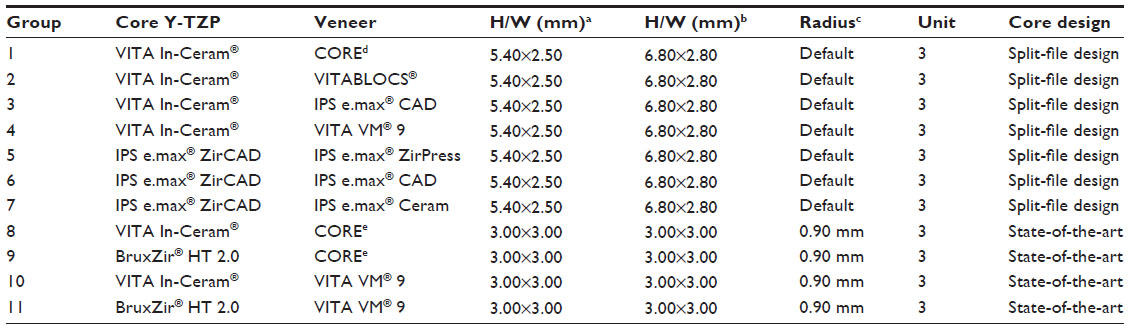 | Table 1 The connector height, width (H/W), radius of gingival embrasure, number of units, material, and core design |
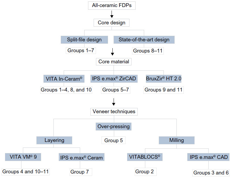 | Figure 1 Overview, all-ceramic fixed dental prostheses (FDPs) groups 1–11, core design, core material, and veneer techniques. |
Preparation
A plastic model of an upper jaw (KaVo YZ, OK VZ 623 0401 180, KaVo Dental GmbH, Biberach, Germany) was used. Two abutment preparations were made: one on the left central incisor and one on the left canine. The aim was to design a structure with a 120° chamfer and a 15° angle of convergence. The left lateral incisor was removed. Subsequently, a full arch A-silicone (Flexitime Mono Phase, Heraeus Kulzer GmbH, Hanau, Germany) impression was made and poured with die stone (Everest® Rock, Type 4 die stone, KaVo Dental GmbH) to produce a master cast.
Scanning
Two different optical scanners were used to manufacture the FDPs. Data for groups 1–7 were generated with Sirona InEos Blue (Sirona Dental Systems GmbH, Bensheim Germany). The master cast was scanned once and the data were transferred to a computer equipped with CAD software (Sirona inLab, version 3.88) where the intended design of the FDP was established. Data for groups 8–11 were generated with 3shape D640 (3Shape A/S, Copenhagen, Denmark). The master cast was scanned once and the data were transferred to a computer equipped with CAD software (Dental-designer 3shape 2013, build 2.8.8.0) where the intended design of the FDP was established.
Split-file design cores
A total of 70 FDP split-file design cores were made. In groups 1–4, the FDPs were made in VITA In-Ceram® YZ for inLab®, YZ-40/15 (VITA Zahnfabrik, Bad Säckingen, Germany). In groups 5–7, the FDPs were made in IPS e.max® ZirCAD for inLab MO 0 B40 (Ivoclar Vivadent AG, Schaan, Liechtenstein).
The connector dimensions of Y-TZP cores in groups 1–7 were set to 5.40×2.50 mm in the left central incisor and 6.80×2.80 mm in the left canine with a bar-shaped occlusal design according to the default settings in the CAD program. The minimum thickness of the core was set to 0.7 mm. The radius of the gingival and occlusal embrasures in the connector areas was selected according to the default settings in the CAD program and the manufacturers’ recommendations (Figure 2). The aim was a split-file design structure that allowed a veneering material with a thickness of 1.5 mm. The CAD data for the FDPs were subsequently sent to a Sirona inLab MCXL milling machine (Sirona Dental Systems GmbH) where they were used to produce FDPs with a split-file design.
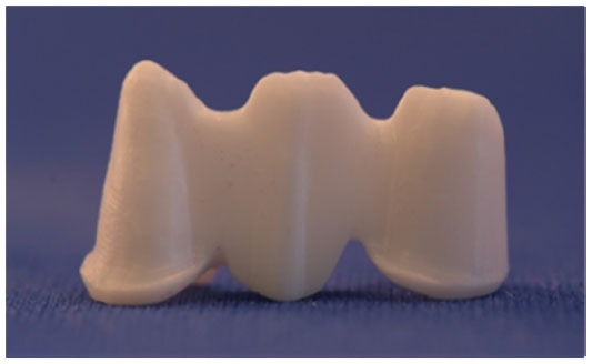 | Figure 2 Y-TZP FDPs split-file design cores in groups 1–7. |
Design of state-of-the-art cores
A total of 40 FDP state-of-the-art cores were made. In groups 8 and 10, the FDPs were made in VITA In-Ceram® YZ DISC, Ø 98×18 mm (VITA Zahnfabrik). In groups 9 and 11, the FDPs were made in BruxZir® HT 2.0, Ø 98×15 mm (Glidewell Laboratories, Newport Beach, LA, USA).
The connector dimensions of the Y-TZP cores in groups 8–11 were set to 3×3 mm and the minimum thickness of the core was set to 0.7 mm. The design radius of the gingival and occlusal embrasures in the connector areas was set to 0.9 mm in the CAD program in accordance with the recommendations of previously published studies (Figure 3). The CAD data for the FDPs were subsequently sent to a Wieland 4030 MN milling machine (Wieland Dental + Technik GmbH, Pforzheim, Germany), with the CAM: Zenotec CAM 2.2.017 software (Wieland Dental + Technik GmbH) where they were used to produce the FDPs.
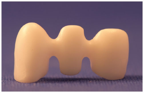 | Figure 3 Y-TZP FDPs state-of-the-art cores in groups 8–11. |
Veneering of the split-file design cores
The design of the veneering materials in groups 2, 3, 5, and 6 was established in accordance with the manufacturers’ recommendations. The veneer structures for group 2 were milled from VITABLOCS® for CEREC®/inLab®, MC XL Mark II 3M2C I-40/19 (VITA Zahnfabrik) and were subsequently luted onto the substructure with Panavia F 2.0 luting cement (Kuraray Medical Inc., Osaka, Japan). The veneers in groups 3 and 6 were milled from ceramic blocks of IPS e.max® CAD for CEREC® and inLab®, HT A3/B40 (Ivoclar Vivadent AG), and were subsequently fused to the substructure with IPS e.max® Crystall./Connect (Ivoclar Vivadent AG). The veneers in group 5 were initially milled from combustible acrylic blocks of IPS AcrylCAD® for inLab B40/L (Ivoclar Vivadent AG), and then they were mounted on the cores and finally produced with the over-pressing technique according to the lost-wax method, IPS e.max® ZirPress (Ivoclar Vivadent AG).
All frameworks of the multilayer veneer were attached following the manufacturers’ instructions.
Manually built-up porcelain
To mimic the shape of the veneers in the milled veneering groups, one of the completed CAD-on FDPs in group 6 was placed on a tooth analog and the undercuts were waxed. The shape of the FDP was duplicated using A-silicone and putty impression material (President, Coltène AG, Altstätten, Switzerland). The layering of veneering porcelain for groups 4, 7, 10, and 11 was then created from the impression. The inner surfaces of the impression were treated with GI-MASK® universal separator for silicones, Coltène® (Coltène/Whaledent AG), and thereafter LPC Isolating Liquid (Ivoclar Vivadent AG) was applied to separate subsequently layered porcelain. VITA VM®9 was used to veneer the FDPs in groups 4, 10, and 11 (VITA Zahnfabrik), and the FDPs in group 7 were layered with IPS e.max® ceram (Ivoclar Vivadent AG). Veneering ceramic for dentine was applied to the FDP frameworks using the impression to achieve a standardized shape and size of the FDPs. All the layered FDPs were then subjected to a first firing. A second layer of dentine ceramic was applied to compensate for the shrinkage caused by sintering. Finally, glaze was applied to the FDPs. All porcelain firing was performed according to the firing programs specified in the manufacturers’ instructions in a calibrated porcelain furnace (Ivoclar P 500, Ivoclar Vivadent AG Schaan).
Heat treatment
The FDP cores in groups 1, 8, and 9 were subjected to heat treatment to simulate the firing cycles of the veneering porcelain VITA VM®9 (VITA Zahnfabrik) according to the manufacturer’s recommendations.
The FDPs in group 2 were excluded from the heat treatment procedure according to the manufacturer’s recommendations.
Thermocycling
As a first stage of the aging procedures, all FDPs underwent thermocycling (LTC Multifunctional Thermocycler, LAM Technologies electronic equipment, Sesto Fiorentino, Italy) using a small basket controlled by a device driver. All FDPs underwent 5,000 thermocycles in two water baths at temperatures of 5°C and 55°C. The FDPs were placed in a basket for transfer between the two baths. Each cycle lasted 60 seconds, 20 seconds in each bath and 10 seconds to complete the transfer between the baths. After thermocycling, the FDPs were dried in air.
Supporting tooth analogs
Tooth analogs for the testing procedure were made using a CAD file at the Nobel Biocare production facility (Procera® Production center, Goteborg, Sweden). According to the recommendations of previous studies, 110 inspection blocks of a polymer material were made to enable precision checking and support the FDPs during testing.20
Cementation
Prior to cementation, the tooth analogs were steam-cleaned and subsequently treated with ED primer II A and B (Kuraray Medical Inc.), which was applied to the cementation surfaces according to the manufacturer’s instructions.
The FDPs of all eleven groups were luted onto the tooth analogs with Panavia F 2.0 luting cement (Kuraray Medical Inc.), using both light and Oxyguard II (Kuraray Medical Inc.), according to the manufacturer’s recommendations. During setting of the cement, all FDPs were loaded in the direction of insertion with a force of 15 N for a period of 60 seconds. After cementation, the FDPs were placed in a plastic container with water covering the bottom surface and a sealing lid to create a humid atmosphere aimed at preventing desiccation of the luting cement.
Preloading
In the second stage of aging, all FDPs were stored in distilled water and mounted at a 10° inclination relative to the vertical plane. The FDPs underwent cyclic preloading at loads between 30 and 300 N, comprising 10,000 cycles and a load profile in the form of a sine wave at 1 Hz. In all groups, the force was applied with a stainless steel indender, 2.5 mm in diameter, with a 1 mm thick plastic foil (Erkoflex, Erkodent® Erich Kopp GmbH, Pfalzgrafenweiler, Germany) placed between the steel indender and the FDPs. To avoid sliding during loading, the indender was placed centrally on the incisal edge of the pontic in the three-unit FDPs.
Load to fracture
In the final stage of testing, the FDPs were mounted in a testing jig at a 10° inclination with a 1 mm thick plastic foil (Erkoflex, Erkodent® Erich Kopp GmbH) placed between the steel indender and centrally on the incisal edge of the pontic. Thereafter, they were subjected to a load applied by a universal testing machine (Instron 4465, Instron Co, Ltd, Norwood, MA, USA). The crosshead speed was 0.255 mm/min and the load was applied with a stainless steel indender, 2.5 mm in diameter. The FDPs were loaded until a fracture occurred, whereupon the loads at fracture were registered. Fracture was defined as a visible crack in the veneer or through the entire construction.
Throughout the test period, whenever the FDPs were not being actively tested, they were stored in distilled water at room temperature.
Analysis
After load to fracture, all the 110 FDPs in the present study were examined and analyzed, both visually and under a light microscope (Leica DFC 420, Leica Application Suite v 3.3.1, Leica Microsystems CMS GmbH, Wetzlar, Germany) to establish the fracture modes.
Moreover, two FDPs, one state-of-the-art and one split-file core, were cut in the connector areas with a diamond saw (IsoMet® 5000 Liner Precision Saw, Buehler, Lake Bluff, IL, USA) and the cross-section areas were measured under the light microscope.
Statistical analysis
Based on null hypothesis, the result will be equal in the following groups:
- the influence of connector design, split-file (VITA In-Ceram®) vs state-of-the-art (VITA In-Ceram®) groups;
- the influence of Y-TZP core material, considering the same core design: a) BruxZir® HT 2.0 vs VITA In-Ceram® and b) VITA In-Ceram® vs IPS e.max® ZirCAD groups;
- the influence of veneering materials on fracture strength and comparison of different material systems, considering the same core manufacturer or design: a) VITABLOCS® vs IPS e.max® CAD, b) VITABLOCS® vs VITA VM® 9, c) VITA VM® 9 vs IPS e.max® CAD, d) IPS e.max® CAD vs IPS e.max® ZirPress, and e) IPS e.max® Ceram vs IPS e.max® ZirPress.
One-way analysis of variance was used in all comparisons. In the comparisons where we compared more than two groups, Tukey’s post hoc test was also used. A significance level of (P≤0.05) was used in all tests.
Results
The fracture data are listed in Table 2. The null hypotheses are rejected.
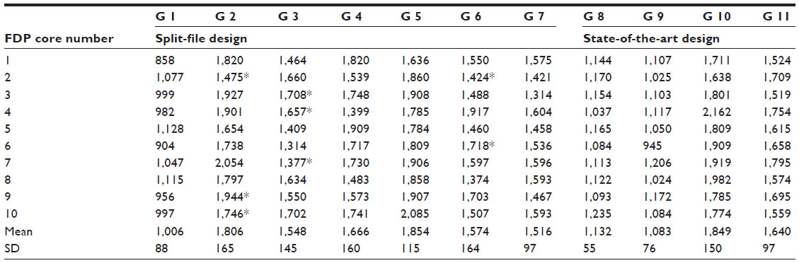 | Table 2 Load at fracture (N) for groups 1–11 |
The fracture mode of the FDPs were determined by three different failure types: either cohesive, (chipping of the veneering ceramic), radial cohesive veneer crack or total fracture through the whole construction. The fracture modes were distributed as follows:
- All the FDPs in group 1 fractured completely in the central connector, starting gingivally with a crack growth toward the loading site on the pontic or involving the connector only.
- In group 2, seven of the FDPs fractured as described earlier for group 1. Three FDPs showed radial cohesive veneer fractures: one FDP in the disto-buccal connector area of the pontic and two FDPs in the mesio-buccal connector area of the pontic.
- In group 3, seven of the FDPs fractured as described earlier for group 1. Three FDPs showed radial cohesive veneer cracks: one FDP in the mesio-buccal connector area of the pontic and two FDPs in both the mesio-buccal and the disto-buccal connector/pontic areas (Figure 4).
- All the FDPs in group 4 fractured in the lateral connector, starting gingivally with a crack growth toward the loading site on the pontic or involving the connector only (Figure 5).
- The FDPs in group 5 fractured in either the central connector (n=6) or the lateral connector (n=4), all starting gingivally with a crack growth toward the loading site on the pontic or involving the connector only.
- The FDPs in group 6 fractured in either the central connector (n=6) or the lateral connector (n=2), all starting gingivally with a crack growth toward the loading site on the pontic or involving the connector only. Two FDPs showed radial cohesive veneer cracks in the mesio-buccal connector area of the pontic.
- All the FDPs in group 7 fractured as described earlier for group 1.
- On all the FDPs in groups 1–7, the fracture was initiated at the sharp indentation in the gingival embrasure area.
- The FDPs in groups 8–11 fractured in either the central connector or the lateral connector, all starting gingivally with a crack growth toward the loading site on the pontic or involving the connector only. The distribution was as follows:
- group 8, three fractures in the central connector and seven in the lateral one;
- group 9, two fractures in the central connector and eight in the lateral one;
- group 10, all FDPs fractured in the lateral connector;
- group 11, two fractures in the central connector and pontic in the lateral one.
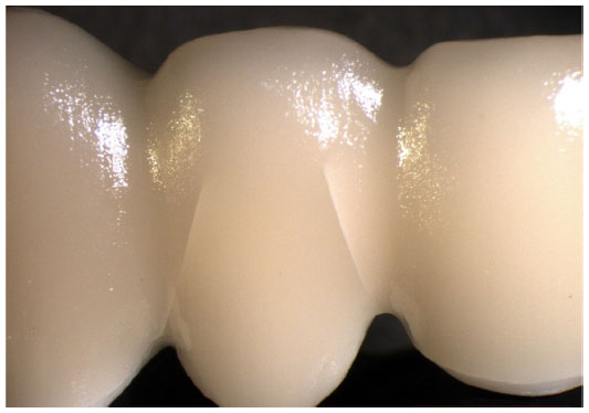 | Figure 4 Visible radial cohesive veneer fracture in groups 2, 3, and 6. |
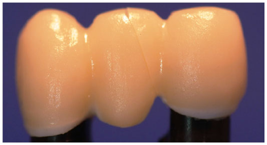 | Figure 5 Fracture mode in group 4 through the connector and the pontic. |
In groups 8–11, all fractures were located in the center of the connector area where the connector dimension was thinnest.
None of the 110 FDPs showed chip-off fractures.
Measurement of the cross-section area
The measurements of the cross-section areas of the split-file core showed that the cross-section area of the connector between the central incisor and the pontic was 11.2 mm2 and the cross-section area between the canine and the pontic was 17.9 mm2. The cross-section area of the connectors on the state-of-the-art core was 7.3 mm2.
Statistical analyses
The influence of connector design, split-file vs state-of-the-art designs showed significant differences in group 1 vs group 8 and group 4 vs group 10.
The influence of Y-TZP core material, considering the same core design showed significant difference in group 10 vs group 11.
The influence of veneering materials on fracture strength and comparison of different material systems, considering the same core manufacturer or design was assessed. Comparisons of groups 1–4 were done (Tukey) and there were significant differences in group 1 vs group 2, group 1 vs group 3, group 1 vs group 4, and group 2 vs group 3. Comparisons of groups 5–7 were done (Tukey) and there were significant differences in group 5 vs group 6, group 5 vs group 7, group 8 vs group 10, and group 9 vs Group 11.
Discussion
In the present study, the specimens were shaped as three-unit FDPs and, when veneering materials were used, they were fabricated as recommended by the manufacturers for restorations intended for clinical use. During testing, environmental aspects were considered in the laboratory setup. To simulate aging of the materials, thermocycling and cyclic preloading in a wet environment were used to mimic the fatigue process in the oral environment.20–26
All FDPs, except the FDPs with luted veneers in group 2, underwent heat treatment, that is, porcelain firing, over-pressing, or crystal fusion. The unveneered groups underwent porcelain firing to assure comparable results since the temperatures that the core is subjected to during porcelain firing may decrease the mechanical properties of the ceramic material. In the case of Y-TZP, a possible explanation is that machine grinding initiates the tetragonal to monoclinic transformation, creating a compressive layer, and that these residual stresses are relaxed during porcelain firing.27–30
The FDPs were thermocycled in order to simulate aging and expose the materials to fatigue. The change in temperature creates stresses corresponding to mechanical stresses in the mouth. The wet environment may also affect the materials by enhancing micro-crack growth due to stress corrosion and slow crack growth. The strength degradation rate is a slow process affecting the all-ceramic material differently depending on several micro-structural parameters, such as – in the case of Y-TZP – yttrium oxide distribution and concentration, flaw distribution, flaw size, and shape and grain size.31,32
Cyclic preloading in an aqueous environment can be performed to simulate aging of the material in the oral cavity during function. It has been reported that ceramic materials show an abrupt strength degradation and transition in damage mode after multicyclic loads compared to static loading tests. Hence, it is essential to consider fatigue and environmental influences, as water in the saliva enhances crack growth in a ceramic restoration when subjected to small alternating forces during mastication in the clinical situation.33,34 To prevent clinically irrelevant Hertzian cone cracks, a thin plastic foil was used during the cyclic preloading and load in fracture procedures.35,36
According to several previous studies, a test method and tooth analogs with a relatively low elastic modulus were used, since the test method must reflect the range and distribution of strength, with consideration being given to the material’s brittle nature.37,38
When testing a material, it is hard to predict and simulate the stress patterns created in the oral cavity and the loads a dental restoration must resist in order to withstand the environmental impact during function over time. Nevertheless, it is preferable to evaluate clinically shaped restorations under environmental conditions close to those present in the oral cavity and compare the results with clinical data on the maximum loads that might occur in the oral cavity.23,24,39
The average maximum bite force varies from one patient to another and individually over time.40–43 Moreover, the range varies from one area of the mouth to another, ~90–900 N.41–43 All veneering materials tested in the present study presented results that exceeded the expected average maximum loads with a large safety margin, indicating sufficient fracture strength, with the lowest mean value being 1,516 N (group 7).
Zirconia for dental use exists in a variety of brands, but the quality of the material is more important. Almost all raw material for zirconia is produced by the same manufacturer, but the quality varies depending on the price. Factors within the production process for the discs and blocks and the techniques for final sintering can also affect the strength of the FDP cores. Since the FDP cores in the present study were produced according to the manufacturers’ instructions and all accepted standards, we assume that the factors mentioned earlier had no influence on the results. Similarly, since all FDPs in this study, except the FDPs in group 2, underwent the same procedures of heat treatment, thermocycling, preloading, luting, and load to fracture, we assume that none of those procedures would introduce sources of error.
In this study, two groups (1 and 8) consisted of non-veneered FDPs produced from the same zirconia brand. Significant differences are apparent when comparing these groups according to the design of the core and particularly the connectors. The split-file designed cores (group 1) have high, thin connectors (default settings: 5.40×2.50 mm between the left central incisor and the pontic and 6.80×2.80 mm between the left canine and the pontic) and small gingival embrasures with sharp notches in the intersectional area of the connectors. The cross-section areas are 11.2 and 17.9 mm2, respectively (Figure 6). Calculating N/mm2 and comparing the frameworks made according to the state-of-the-art design with a cross-section of 7.3 mm2 (Figure 7), the split-file designed cores demand a connector cross-section area almost 42% (or 62% if comparing with the largest connector) enlarged in the vertical aspect to receive nearly the same load at fracture values as the state-of-the-art cores. The height and the size of the connectors are probably the most important factors in the relatively high fracture strength but the split-file design FDP cores still show a lower fracture strength than the cores designed according to the state-of-the-art (group 8) with connector dimensions of 3×3 mm and a 0.90 mm radius of the gingival embrasures. This confirms results from previous studies.6–8,26,44 A further explanation for the lower fracture strength of the non-veneered split-file design FDPs could be the small radius of the gingival embrasures, which in fact acts as a fractural impression. To prevent the radius of the gingival embrasures from being too small, it must be possible for the dental technician to control the radius settings in the CAD software. This was not the case here. The radius of the gingival embrasures was already determined by the default setting of the Sirona system.
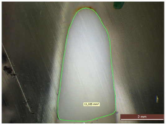 | Figure 6 Measurement of a cut split-file Y-TZP FDP core under light microscope. |
 | Figure 7 Measurement of a cut state-of-the-art Y-TZP FDP core under light microscope. |
Another problem with the split-file design cores is the hygiene aspect. The design of the gingival embrasures has to be rather bulky in order to allow sufficient fracture strength of the core material and enable a superstructure to fit accurately on the core. This could compromise the patient’s ability to maintain oral hygiene.45 The split-file shaped design could also be a disadvantage with regard to esthetics. The construction, with both core and veneer, tends to be somewhat bulky, and as the veneering material is monocolored, the technique is probably most suitable for posterior use.
In the present study, several different techniques for veneering full-ceramic substructures were studied. In all groups consisting of veneered FDPs, there was an obvious and statistically significant increase in the fracture strength, compared to the non-veneered groups, which shows that the complete material systems are more reliable than each component on its own. According to the manufacturers, the core material Y-TZP (IPS e.max® ZirCAD, VITA IN-Ceram® YZ for InLab®) has a flexural strength of up to 900 MPa, the materials for the milled veneers (IPS e.max® CAD lithium disilicate, VITABLOCS® for CEREC®/inLab®, feldspar) 360 and 154 MPa respectively, the fluorapatite heat-pressing material (IPS e.max® ZirPress) 110 MPa, the porcelains used for the layering technique (IPS e.max® Ceram, nano-fluorapatite, VITA VM® 9, feldspar) 90 and 100 MPa respectively, and the fusion glass (IPS e.max® Crystall./Connect) 160 MPa. Finally, the luting cement (Panavia F 2.0) has a shear bond strength between 25 and 44 MPa, depending on the luting surface.
There were four groups veneered with the build-up porcelain layering technique. Two of these were split-file design substructures made from two different material systems with the same design. The reason for combining split-file cores with build-up veneer materials was to be able to compare the strength of the split-file cores with that of the state-of-the-art cores, taking the influence of the veneering technique into consideration. The split-file/build-up combinations are, however, only for investigational purposes and should not be used in the clinical situation. Group 4 FDPs were layered with conventional veneering porcelain and group 7 FDPs were layered with a veneering glass–ceramic based on fluorapatite. When studying the result of the fracture strength test, there was a difference between the two groups, favoring group 4, which correlates with the result of previous studies.46,47 This result was, however, only numerical and not statistically significant.
The other two groups with porcelain built-up veneers were groups 10 and 11. The substructures were fabricated according to state-of-the-art design and the design of the veneers was identical to the split-file groups 4 and 7 mentioned previously. The only difference was the material and design of the substructure. The FDPs in group 10 were made from traditional Y-TZP, layered with the conventional porcelain also used in group 4. The same porcelain was used for the FDPs in group 11 but the substructures consisted of high-translucent stabilized zirconia which is mainly intended for use in full-anatomical, monolithic constructions. When used as intended, that is, full-anatomical, the highly translucent zirconia performs with a higher fracture strength than in the present study but here the fracture strength value was significantly lower than those for the conventional constructions in group 10. Nevertheless, the fracture strength value was sufficient to assume that the highly translucent zirconia can be used as a substructure for all-ceramic FDPs. The material is currently designed for use either as full-anatomical constructions, characterized with painted stains on the surface, or for use with different degrees of cut-backs in the labial/buccal areas which are then layered with porcelain to achieve better esthetics. In those cases, the whole construction would produce a higher fracture strength value since the bulk of the core material is thicker and therefore more resistant to loads as a result of masticatory forces.21 It could be assumed, however, that the full anatomic design, which is challenging when considering the possibility to design the FDPs with high-radius interproximal embrasures, compels a design with sharp notch-like separations that might act as a fractural impression. If that is the case, higher demands on the minimum connector dimensions are needed to compensate for impaired shape. This is not yet fully investigated though and compels further studies.
The only difference between groups 4 and 10 is the design of the substructures where the small radius of the gingival embrasures in group 4 probably was the reason for the lower fracture strength value in this group (P<0.05). Comparing the fracture strength values in respect of the cross-section areas of the connectors, the same relation between the split-file and the state-of-the-art cores remains, regardless of veneered or non-veneered core; that is, the split-file cores demand at least 42% larger cross-section area of the connector to withstand the same fracture load as the state-of-the-art FDPs.
In the present study, three groups were fabricated with milled veneers: groups 2, 3, and 6. The veneering technique raised the overall fracture strength values for all three groups but the mean value for group 2 (only statistically comparable with group 3), where VITABLOCS® was used to fabricate the veneers, was significantly higher than for the others, where IPS e.max® CAD was used for fabricating the veneers.
There were no significant differences in strength between groups 3 and 6, two different brands of the same material, which indicate that the material brand did not influence the results in the present study.
The higher fracture loads in group 2 require some discussion. First, the veneering material (VITABLOCS® for CEREC®/inLab®) is not as strong as the veneering material in group 3. This is according to the manufacturers’ information and is also due to the fact that feldspar is known to have a slightly lower fracture value than fluorapatite. In addition, according to other studies,48,49 a fused superstructure should produce a higher fracture strength than a luted superstructure, especially after simulated aging given that the resin cement is more sensitive to simulated aging than the sintered glass–ceramic. In the present study, however, the luted veneers in group 2 produced a significantly higher result than the crystal-fused group 3. If the FDPs had been exposed to a longer period of thermocycling, the luting cement might have dissolved, leading to a lower fracture resistance.
Moreover, the fact that the FDPs in group 2 were excluded from the heat treatment, a procedure that might have decreased the mechanical properties of the ceramic material, could also have had an effect on the result.
Another possible explanation for this rather unexpected result could be that the procedure for fusing the veneers to the core is a technique-sensitive method. The connecting glass is vibrated between the core and the veneer and there is a risk of air becoming trapped and later creating porosities along the surfaces connected. The risk of porosities is probably higher when attempting to cover a relatively large surface as is the case in the present study where the FDPs consist of a three-unit construction rather than in the single units tested in other studies.49,50 This indicates that the overall fracture value depends on the homogeneity of the connecting agent. When studying the fracture mode of the veneers under a microscope, the images clearly show a higher quantity of porosities along the interfacial surface of the glass-fused groups 3 and 6 than on the luted surface in group 2. Moreover, the fracture mode also differs between the glass-fused and luted groups. In all groups, the fracture starts in the gingival part of the connector area on the surface of the veneering material. In the rather homogeneous lithium disilicate ceramic material, the fracture propagates straight through the veneer all the way through the fusion layer where it then continues via the porosities along the interface between the fusion layer and the Y-TZP core (Figure 8). In the luted group, the fracture propagates via the porosities within the veneering material but is obstructed before it reaches the cement layer (Figure 9).
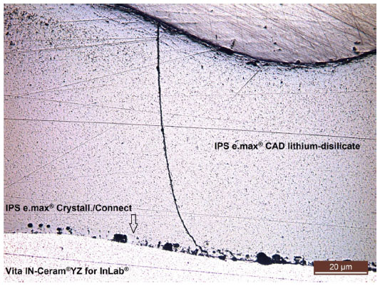 | Figure 8 Fracture mode of the veneer in group 3 under light microscope. |
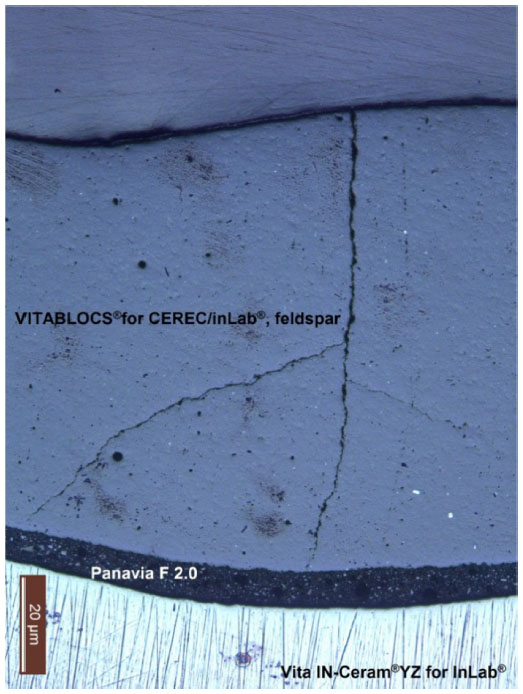 | Figure 9 Fracture mode of the veneers in luted group 2 under light microscope. |
An interesting finding within the aforementioned three groups is that these are the only groups where, in some cases (20%–30%), visible radial cohesive cracks occurred (Figure 4). A possible explanation for these cracks could be that the milling process creates crack initiators on the inner surface of the veneering material.51–53 Luting the veneering structure to the substructure (VITABLOCS®) or crystal fusing the veneering structure to the substructure (IPS e.max® CAD) may not create adequate and homogeneous filling of the defects created by the milling process.53 When comparing the results of the present study with other studies of the CAD-on technique, the results are reversed. Most of those studies show that the CAD-on technique creates fewer or no radial cohesive veneer fractures due to the homogeneity of the veneering material. However, these studies are undertaken with single constructions and the load-bearing tests are performed on tooth analogs made from metal. Stiff analogs are known to increase the load-bearing capacity of an all-ceramic construction and the choice of less stiff analogs in this study might explain the opposing results.20 There is also a difference in stress distribution between a single crown and an FDP, with connectors and pontics, which also might explain the differing results.
All groups cannot be compared statistically, but overviewing the results shows over-press technic group 5 achieved the same fracture values as groups 2 and 10, but they cannot be compared statistically. Tsalouchou et al54 reached an equivalent conclusion when testing over-pressed veneers and layered veneers. So did Beuer et al,50 but in this study, the split-file technique with fused veneers produced twice the fracture strength of the other techniques. A final remark is that the results in the present study need to be confirmed by clinical studies.
Conclusion
Within the limitations of this in vitro study, we made the following conclusions: The shape of a split-file designed all-ceramic reconstruction calls for a different dimension protocol, compared to traditionally shaped ones, as the split-file design leads to sharp approximal indentations acting as fractural impressions, thus decreasing the overall strength. The design of a framework is a crucial factor for the load bearing capacity of an all-ceramic FDP. The state-of-the-art design is preferable since the split-file designed cores call for a cross-sectional connector area, at least 42% larger, to have the same load-bearing capacity as the state-of-the-art designed cores. Analysis of the fracture pattern shows differences between the milled veneers and over-pressed or built-up veneers, where the milled ones show numerically more veneer cracks and the other groups only show complete connector fractures.
Acknowledgments
All the VITA® materials were kindly provided by Denthouse AB, Sundbyberg, Sweden, and VITA Zahnfabrik, Germany. All the IPS e.max® materials were kindly provided by Ivoclar Vivadent AB, Solna, Sweden. The BruxZir® FDPs were kindly provided by Cosmodent AB, Malmö, Sweden. The Panavia F 2.0 cement was kindly provided by RH Dental ApS, Gentofte, Denmark. The tooth analogs were kindly provided by Nobel Biocare, Zurich, Switzerland.
This paper and the abstract of this paper were presented at the Swedental and Annual Dental Congress, November 13, 2015 in Götenborg, Sweden (http://invitepeople.com/public/seminars/3909?lang=en). The actual paper, however, has never been previously published.
Disclosure
The authors report no conflicts of interest in this work.
References
Besimo CE, Spielmann HP, Rohner HP. Computer-assisted generation of all-ceramic crowns and fixed partial dentures. Int J Comput Dent. 2001;4(4):243–262. | |
McLaren EA, Terry DA. CAD/CAM systems, materials, and clinical guidelines for all-ceramic crowns and fixed partial dentures. Compend Contin Educ Dent. 2002;23(7):637–641, 644, 646 passim; quiz 654. | |
Filser F, Kocher P, Weibel F, Lüthy H, Schärer P, Gauckler LJ. Reliability and strength of all-ceramic dental restorations fabricated by direct ceramic machining (DCM). Int J Comput Dent. 2001;4(2):89–106. | |
Reich S, Wichmann M, Nkenke E, Proeschel P. Clinical fit of all-ceramic three-unit fixed partial dentures, generated with three different CAD/CAM systems. Eur J Oral Sci. 2005;113:174–179. | |
Kamposiora P, Papavasiliou G, Bayne SC, Felton DA. Stress concentration in all-ceramic posterior fixed partial dentures. Quintessence Int. 1996;27(10):701–706. | |
Oh W, Gotzen N, Anusavice KJ. Influence of connector design on fracture probability of ceramic fixed partial dentures. J Dent Res. 2002;81(9):623–627. | |
Oh WS, Anusavice KJ. Effect of connector design on the fracture resistance of all-ceramic fixed partial dentures. J Prosthet Dent. 2002; 87(5):536–542. | |
Bahat Z, Mahmood DJ, Vult von Steyern P. Fracture strength of three-unit fixed partial denture cores (Y-TZP) with different connector dimension and design. Swed Dent J. 2009;33(3):149–159. | |
Zarone F, Russo S, Sorrentino R. From porcelain-fused-to-metal to zirconia: clinical and experimental considerations. Dent Mater. 2011; 27(1):83–96. | |
Heintze SD, Rousson V. Survival of zirconia- and metal-supported fixed dental prostheses: a systematic review. Int J Prosthodont. 2010;23(6):493–502. | |
Guess PC, Att W, Strub JR. Zirconia in fixed implant prosthodontics. Clin Implant Dent Relat Res. 2012;14(5):633–645. | |
Al-Amleh B, Lyons K, Swain M. Clinical trials in zirconia: a systematic review. J Oral Rehabil. 2010;37(8):641–652. | |
Aboushelib MN, de Jager N, Kleverlaan CJ, Feilzer AJ. Microtensile bond strength of different components of core veneered all-ceramic restorations. Dent Mater. 2005;21(10):984–991. | |
Fischer J, Grohmann P, Stawarczyk B. Effect of zirconia surface treatments on the shear strength of zirconia/veneering ceramic composites. Dent Mater J. 2008;27(3):448–454. | |
Taskonak B, Yan J, Mecholsky JJ Jr, Sertgöz A, Koçak A. Fractographic analyses of zirconia-based fixed partial dentures. Dent Mater. 2008; 24(8):1077–1082. | |
Zheng Z, Lin J, Shinya A, Matinlinna JP, Botelho MG, Shinya A. Finite element analysis to compare stress distribution of gold alloy, lithium-disilicate reinforced glass ceramic and zirconia-based fixed partial denture. J Investig Clin Dent. 2012;3(4):291–297. | |
Kanat B, Comlekoglu EM, Dundar-Comlekoglu M, Hakan Sen B, Ozcan M, Ali Güngör M. Effect of various veneering techniques on mechanical strength of computer-controlled zirconia framework designs. J Prosthodont. 2014;23(6):445–455. | |
Fischer J, Stawarczyk B, Hammerle CH. Flexural strength of veneering ceramics for zirconia. J Dent. 2008;36(5):316–321. | |
Wiedhahn K. The impression-free Cerec multilayer bridge with the CAD-on method. Int J Comput Dent. 2011;14(1):33–45. | |
Mahmood DJ, Linderoth EH, Vult Von Steyern P. The influence of support properties and complexity on fracture strength and fracture mode of all-ceramic fixed dental prostheses. Acta Odontol Scand. 2011;69(4):229–237. | |
Johansson C, Kmet G, Rivera J, Larsson C, Vult Von Steyern P. Fracture strength of monolithic all-ceramic crowns made of high translucent yttrium oxide-stabilized zirconium dioxide compared to porcelain-veneered crowns and lithium disilicate crowns. Acta Odontol Scand. 2014;72(2):145–153. | |
Larsson C, El Madhoun S, Wennerberg A, Vult von Steyern P. Fracture strength of yttria-stabilized tetragonal zirconia polycrystal crowns with different design: an in-vitro study. Clin Oral Implants Res. 2012;23(7):820–826. | |
Kelly JR. Clinically relevant approach to failure testing of all-ceramic restorations. J Prosthet Dent. 1999;81(6):652–661. | |
Anusavice KJ, Kakar K, Ferree N. Which mechanical and physical testing methods are relevant for predicting the clinical performance of ceramic-based dental prostheses? Clin Oral Implants Res. 2007; 18 Suppl 3:218–231. | |
Kohorst P, Dittmer MP, Borchers L Stiesch-Scholz M. Influence of cyclic fatigue in water on the load-bearing capacity of dental bridges made of zirconia. Acta Biomater. 2008;4(5):1440–1447. | |
Mahmood D, Linderoth E, Vult von Steyern P, Wennerberg A. Fracture strength of all-ceramic (Y-TZP) three- and four-unit fixed dental prostheses with different connector design and production history. Swed Dent J. 2013;37(4):179–187. | |
Rekow ED, Silva NR, Coelho PG, Zhang Y, Guess P, Thompson VP. Performance of dental ceramics: challenges for improvements. J Dent Res. 2011;90(8):937–952. | |
Kelly JR. Perspectives on strength. Dent Mater. 1995;11(2):103–110. | |
Kheradmandan S, Koutayas SO, Bernhard M, Strub JR. Fracture strength of four different types of anterior 3-unit bridges after thermo-mechanical fatigue in the dual-axis chewing simulator. J Oral Rehabil. 2001;28(4):361–369. | |
Raigrodski AJ, Chiche GJ. The safety and efficacy of anterior ceramic fixed partial dentures: a review of the literature. J Prosthet Dent. 2001;86(5):520–525. | |
Hannink RHJ, Kelly PM, Muddle BC. Transformation toughening in zirconia-containing ceramics. J Am Ceram Soc.2000;83:461–487. | |
Lange FF, Dunlop GL, Davis BI. Degradation during aging of transformation-toughened ZrO2-Y2O3 materials at 250°C. J Am Ceram Soc. 1986;69(3):237–240. | |
Chevalier J, Loh J, Gremillard L, Meille S, Adolfson E. Low-temperature degradation in zirconia with a porous surface. Acta Biomater. 2011;7(7):2986–2993. | |
Koutayas SO, Kern M, Ferraresso F, Strub JR. Influence of framework design on fracture strength of mandibular anterior all-ceramic resin-bonded fixed partial dentures. Int J Prosthodont. 2002;15(3):223–229. | |
Vult von Steyern P, al-Ansari A, White K, Nilner K, Dérand T. Fracture strength of In-Ceram all-ceramic bridges in relation to cervical shape and try-in procedure. An in-vitro study. Eur J Prosthodont Restor Dent. 2000;8(4):153–158. | |
Bhowmick S, Melendez-Martinez JJ, Hermann I, Zhang Y, Lawn BR. Role of indenter material and size in veneer failure of brittle layer structures. J Biomed Mater Res B Appl Biomater. 2007;82(1):253–259. | |
Kelly JR, Tesk JA, Sorensen JA. Failure of all-ceramic fixed partial dentures in-vitro and in-vivo: analysis and modeling. J Dent Res. 1995; 74(6):1253–1258. | |
Luthardt RG, Holzhuter M, Sandkuhl O, et al. Reliability and properties of ground Y-TZP-zirconia ceramics. J Dent Res. 2002;81(7):487–491. | |
Quinn GD, Studart AR, Hebert C, VerHoef JR, Arola D Fatigue of zirconia and dental bridge geometry: design implications. Dent Mater. 2010;26(12):1133–1136. | |
Koc D, Dogan A, Bek B. Bite force and influential factors on bite force measurements: a literature review. Eur J Dent. 2010;4(2):223–232. | |
Lassila V, Holmlund I, Koivumaa KK. Bite force and its correlations in different denture types. Acta Odontol Scand. 1985;43(3):127–132. | |
Helkimo E, Carlsson GE, Helkimo M. Bite force and state of dentition. Acta Odontol Scand. 1977;35(6):297–303. | |
Waltimo A, Kononen M. Maximal bite force and its association with signs and symptoms of craniomandibular disorders in young Finnish non-patients. Acta Odontol Scand. 1995;53(4):254–258. | |
Ambre MJ, Aschan F, Vult von Steyern P. Fracture strength of yttria-stabilized zirconium-dioxide (Y-TZP) fixed dental prostheses (FDPs) with different abutment core thicknesses and connector dimensions. J Prosthodont. 2013;22(5):377–382. | |
Pissiotis AL, Michalakis KX. An esthetic and hygienic approach to the use of intracoronal attachments as interlocks in fixed prosthodontics. J Prosthet Dent. 1998;79(3):347–349. | |
Marrelli M, Maletta C, Inchingolo F, Alfano M, Tatullo M. Three-point bending tests of zirconia core/veneer ceramics for dental restorations. Int J Dent. 2013;2013:831976. | |
Stawarczyk B, Ozcan M, Hammerle CH, Roos M. The fracture load and failure types of veneered anterior zirconia crowns: an analysis of normal and Weibull distribution of complete and censored data. Dent Mater. 2012;28(5):478–487. | |
Schmitter M, Mussotter K, Rammelsberg P, Stober T, Ohlmann B, Gabbert O. Clinical performance of extended zirconia frameworks for fixed dental prostheses: two-year results. J Oral Rehabil. 2009;36(8):610–615. | |
Schmitter M, Schweiger M, Mueller D, Rues S. Effect on in-vitro fracture resistance of the technique used to attach lithium disilicate ceramic veneer to zirconia frameworks. Dent Mater. 2014;30(2):122–130. | |
Beuer F, Schweiger J, Eichberger M, Kappert HF, Gernet W, Edelhoff D. High-strength CAD/CAM-fabricated veneering material sintered to zirconia copings – a new fabrication mode for all-ceramic restorations. Dent Mater. 2009;25(1):121–128. | |
Hung CY, Lai YL, Hsieh YL, Chi LY, Lee SY. Effects of simulated clinical grinding and subsequent heat treatment on microcrack healing of a lithium disilicate ceramic. Int J Prosthodont. 2008;21(6):496–498. | |
Jing Z, Ke Z, Yihong L, Zhijian S. Effect of multistep processing technique on the formation of micro-defects and residual stresses in zirconia dental restorations. J Prosthodont. 2014;23(3):206–212. DOI:10.1111/jopr.12094. | |
Flury S, Peutzfeldt A, Lussi A. Influence of surface roughness on mechanical properties of two computer-aided design/computer-aided manufacturing (CAD/CAM) ceramic materials. Oper Dent. 2012;37(6):617–624. | |
Tsalouchou E, Cattell MJ, Knowles JC, Pittayachawan P, McDonald A. Fatigue and fracture properties of yttria partially stabilized zirconia crown systems. Dent Mater. 2008;24(3):308–318. |
 © 2016 The Author(s). This work is published and licensed by Dove Medical Press Limited. The
full terms of this license are available at https://www.dovepress.com/terms
and incorporate the Creative Commons Attribution
- Non Commercial (unported, 3.0) License.
By accessing the work you hereby accept the Terms. Non-commercial uses of the work are permitted
without any further permission from Dove Medical Press Limited, provided the work is properly
attributed. For permission for commercial use of this work, please see paragraphs 4.2 and 5 of our Terms.
© 2016 The Author(s). This work is published and licensed by Dove Medical Press Limited. The
full terms of this license are available at https://www.dovepress.com/terms
and incorporate the Creative Commons Attribution
- Non Commercial (unported, 3.0) License.
By accessing the work you hereby accept the Terms. Non-commercial uses of the work are permitted
without any further permission from Dove Medical Press Limited, provided the work is properly
attributed. For permission for commercial use of this work, please see paragraphs 4.2 and 5 of our Terms.