Back to Journals » Journal of Pain Research » Volume 18
Anatomical and Technical Considerations of CT-Guided C1-C2 Lateral Joint Injections: Technique, Pitfalls, and Risks
Authors Mohajer B, Qazi ZN ![]() , Carrino JA, Chazen JL, Schatman ME
, Carrino JA, Chazen JL, Schatman ME ![]() , Yoon ES
, Yoon ES ![]()
Received 28 December 2024
Accepted for publication 5 November 2025
Published 17 November 2025 Volume 2025:18 Pages 6111—6124
DOI https://doi.org/10.2147/JPR.S514705
Checked for plagiarism Yes
Review by Single anonymous peer review
Peer reviewer comments 2
Editor who approved publication: Dr Rune Häckert Christensen
Bahram Mohajer,1,2 Zain Naeem Qazi,1 John A Carrino,1 J Levi Chazen,1 Michael E Schatman,3 Edward S Yoon1
1Department of Radiology, Hospital for Special Surgery, New York, NY, USA; 2Department of Radiology, Hospital of the University of Pennsylvania, Philadelphia, PA, USA; 3Department of Anesthesiology, Perioperative Care and Pain Medicine, Department of Population Health - Division of Medical Ethics, NYU Grossman School of Medicine, New York, NY, USA
Correspondence: Edward S Yoon, Hospital for Special Surgery, Radiology, 535 East 70th St, New York, NY, 10021, USA, Email [email protected]
Abstract: Cervicogenic headaches, often originating from the upper cervical spine, represent a significant chronic pain condition. The C1-C2 joint, comprising synovial-lined lateral mass articulations and a pivot joint, is a common pain generator. Understanding the intricate anatomy, including the important anatomical adjacencies, innervation, and pathology of these joints, is crucial for effective intervention. This review highlights the importance of preprocedural evaluation, patient positioning, and CT-guided injection technique to minimize complications. The benefits of CT over fluoroscopic guidance for these procedures are also examined, providing a step-by-step guide to ensure accurate and safe needle placement and injection. Additionally, this manuscript reviews potential risks such as intravascular injection and nerve damage, offering strategies to mitigate these risks. This comprehensive analysis aims to enhance the understanding and execution of C1-C2 joint injections, ultimately improving patient outcomes. Moreover, this review demonstrates the effectiveness and safety of the C1-2 joint injections under CT guidance.
Keywords: cervicogenic headache, facet injection, CT guided, spine, facet arthritis, interventional pain
Cervicogenic Headaches
In the 1900s, chiropractors, surgeons, and physiatrists initiated attempts at cervical spine analgesic interventions.1 Cervicogenic headaches were first documented in the literature by Sjaastad et al in 1983,2 and since then, the understanding of the pathophysiology and anatomy of cervicogenic headaches has continued to be refined. At a fundamental level, they are headaches caused by pain referred from a pathologic process originating in the cervical spine, specifically afferent nerve sensation from anatomy involving the upper three cervical nerve roots. The incidence of cervicogenic headaches is estimated to be between 0.4% and 2.5%, and they are more frequently encountered in patients with chronic headaches in pain clinics.3,4
The implicated anatomy includes cervical synovial joints, cervical muscles, the intervertebral disc, the arteries of the upper neck, and the dura mater.5 There is a convergence of nociceptive afferent fibers from the caudal extension of the 1st division of the trigeminal nerve to the outer lamina of the dorsal horn, as well as afferents from the C1 (short muscles of the suboccipital triangle), C2 (median and lateral atlantoaxial joints), and C3 (zygapophyseal joints and discs) spinal nerves, which explain the referred pain. The most commonly implicated sources for cervicogenic headache are the C2-C3 zygapophyseal joints, where the third occipital nerve is affected, with lateral atlantoaxial joints as the second most likely site.3 The unique anatomy of the upper cervical spine, along with its proximity to critical surrounding structures and limited intervening space, can be a source of apprehension when considering interventions. The anatomy, risks, technical considerations, and potential pitfalls involved in performing CT and fluoroscopically guided C1-C2 lateral mass articulation injections are discussed in this article.
C1-C2 Joint Anatomy
The atlanto-axial or C1-C2 articulations comprise three distinct joints: two synovial-lined lateral mass joints (“facet joints”) and one pivot joint involving the dens and the arch of C1 (Figure 1). The synovial reflections around these joints vary and may communicate anteriorly across the anterior arch-odontoid articulation. This provides the basis for the understanding of the contrast spread pattern discussed later in this article. The combined volume capacity of these synovial joints typically limits to approximately 3.5–4 mL when communicating, and approximately half that when not communicating. Given the presence of synovium, any pathology affecting a synovial-lined joint can similarly impact the C1-C2 lateral mass joints.6–9 Such pathologies may include infection, inflammatory diseases (rheumatoid arthritis, gout), or malignancy/metastatic disease—all of which are exceedingly rare etiologies. In our experience, when these joints are involved in pain, most cases involve degenerative or post-traumatic arthrosis.
 |
Figure 1 Schematic illustration and CT view of the C2 dorsal root ganglion (DRG), lateral atlanto-axial joint, and surrounding bony structures. (A) Schematic coronal view. (B) Coronal and (C) sagittal slices of a CT scan of the cervical spine with bone algorithm obtained at the level of one of the lateral atlantoaxial joints. The dashed white line highlights the C1-C2 lateral mass articulation (“facet”) joint, which is the second most common level involved in cervicogenic headache. Under both bone and soft tissue algorithms, muscles, fat, and bone can be fairly well distinguished, although MRI offers greater utility for evaluating soft tissues due to superior soft tissue contrast. Dashed line (┋): C1-C2 lateral mass articulations; arrow (↑): inferior articular processes of C1; arrowhead (►): superior articular processes of C2; white circle (●): anatomical location of C2 DRG. |
C1-C2 Joint Innervation & Pathology
The dorsolateral aspects of the C1-C2 facet joints are innervated by 5–9 articular branches originating from different parts of the C2 nerve (dorsal root ganglion, ventral spinal nerve, ventral ramus). Additionally, a prevertebral nerve plexus has been described.10,11 The C2 dorsal root ganglion is located at the neural foramen at the dorsal margin of the lateral mass articulations and can be encountered from a posterior approach (Figure 2). However, this makes it an unappealing target for rhizotomy, as this can cause painful numbness or anesthesia dolorosa.
 |
Figure 2 Important anatomical proximities of the C1-C2 lateral joint. (A) Axial T2-weighted MRI of the upper cervical spine shows the right C2 dorsal root ganglion, which may be encountered from a posterior approach to the C1-C2 lateral mass articulation. (B) Same plane, illustrating the location of the ventral ramus of C2, the lateral/outer margin of the dural sac, and the vertebral artery at the margin of the atlanto-axial joint. (C) Coronal CT image with an overlaid transparent coronal T2-weighted MRI image showing the lateral border of the thecal sac marked by the dashed line. In this patient, at the medial margin of the C1-C2 facet joint, the dorsal root ganglion is highlighted (white arrow ↑), emphasizing the importance of staying at the lateral margin of the joint. Posterior to these structures is the cervical musculature (obliquus capitis inferior muscle) and posterior to the flow void from the left deep cervical vein. (D) MIP coronal CT angiography images demonstrating the relative position of the vertebral arteries at the lateral margin of the C1-C2 lateral mass articulation. Axial CT at the potential level of the C1-C2 lateral mass articulation injection under CT shows the location of the vertebral artery at the lateral margin of the facet joint. Note that the vertebral artery exhibits significant variation in position relative to the joint, and a minority of patients can be along a trajectory from a posterior approach for injection. This underscores the importance of using contrast in performing an arthrogram before administering the injectate. |
Previous studies have shown that noxious stimulation to the C1-C2 facet joints through contrast injection causes suboccipital/occipital pain.12 In contrast, diagnostic injections to the C1-C2 facet joints with anesthetic have been effective in relieving occipital pain and pain referred to other regions of the head.4 Bogduk et al found that lateral atlanto-axial joint pathology may account for 16% of patients with occipital headaches.6 As noted earlier, the most implicated etiologies are osteoarthritis and trauma; the former demonstrates subchondral sclerosis, osteophytosis, joint space narrowing, and cysts on CT (Figure 3A). Bone marrow edema can be seen on fluid-sensitive MRI sequences (Figures 3B and C). Previous research indicates that atlantoaxial arthritis is radiographically present in about 4.8% of patients, rising to 18.2% in the ninth decade of life.13 It is found in 12% of cases as degenerative arthrosis isolated to lateral mass joints, 17% affecting the atlanto-odontoid joint, and both areas in 71% of patients.14,15 These conditions are symptomatic in 4% of patients, more often in females (74%), and unilaterally (76%).16
 |
Figure 3 Degenerative disease of the C1-C2 lateral joint. Sagittal CT with bone algorithm (A) and sagittal STIR sequence from a cervical spine MRI (B and C) demonstrate the right C1-C2 lateral mass articulation with signs of degenerative arthrosis, including joint space narrowing (dashed line ┋), subchondral sclerosis (curved arrow ⤸), cystic changes (arrow ↑), and marginal osteophytes (arrowhead ►). The corresponding sagittal MRI illustrates bone marrow edema (star ★) in the inferior articular pillar of C1, along with a small amount of soft tissue edema just posterior to the facet joint. Additional sagittal C2 magnetic resonance image of the contralateral C1-C2 articulation (C) demonstrates a relatively normal articulation. |
C1-C2 Joint Pain & Therapeutic Intervention
As with many painful processes, there is variability and subjectivity in how cervicogenic headache pain is perceived, which often leads to inaccurate clinical diagnosis. This pain may originate in the upper cervical spine and radiate to the frontal, temporal, or occipital areas, and it can be either unilateral or bilateral. Due to the complex anatomy, overlapping pathologies, and variable innervation of different structures in this region, physical exam findings are challenging to localize precisely to the pathology of the C1-C2 lateral mass articulations.17 The International Headache Society and the International Classification of Headache Disorders aim to standardize diagnostic criteria.18 These criteria include clinical, laboratory, and/or imaging findings that demonstrate a disorder or lesion in the spine or paraspinal soft tissues of the neck. In addition to confirming a cervical source of the pain, a controlled diagnostic block is necessary to establish the cervical source as the pain generator.
Given the unique anatomy of the innervation to the C1-C2 joint, the therapeutic options for symptomatic relief are limited. At one end of the spectrum, patients may try physical therapy and anti-inflammatory medications, some of which have been demonstrated to be effective for cervicogenic headaches, although they mostly have minimal or moderate effect sizes.19 Conversely, one may choose to undergo instrumented arthrodesis of the C1-C2 joint, which subsequently limits the capacity to rotate the head and carries risks, morbidity, and mortality associated with cervical spinal surgery.20 However, the surgical literature suggests satisfactory pain relief for over 2 years in some patients based on observational studies.16,21,22 Injections into the C1-C2 facet joints have also been found to be beneficial, achieving successful improvement of at least 50% pain in 81% of patients and providing relief for up to 3 months post-injection.23 Additionally, there is literature on neurectomy of the greater and less occipital nerves, as well as ligation of the adjacent occipital arteries, which has provided relief in 86% of patients.24 However, this study did not include a trial of a C2 DRG nerve block, nor does it mention whether C1-2 facet joint arthrosis was seen on any of the imaging studies.
Indications
The primary indication for C1-C2 lateral mass articulation injections is for diagnostic purposes—to determine, once other pathology has been excluded such as facet arthrosis and migraines—whether the C1-2 facet joint is the source of the patient’s headaches. Additionally, MRI can be used to identify edema or joint effusions before considering an injection. The absence of edema or effusion on MRI suggests that the C1-2 articulation is unlikely to be the cause of the patient’s neck pain or headaches. Patients often present with occipital neuralgia-like symptoms on the same side as the joint arthrosis and impingement of the C2 dorsal root ganglion (DRG). Due to the potential risks of accessing the C1-C2 facet joint, many interventionists prefer to administer steroids during the diagnostic injection to achieve a longer-lasting therapeutic response to the diagnostic injection. As such, determining whether prolonged symptom relief is due to the local anesthetic or the steroid can be challenging. The patient’s pain level should be documented on a numerical scale and through pain drawings before the procedure, including details about the pain’s characterization and location. After the injection, the patient should be instructed to record their response in a pain diary to help determine if the C1-C2 facet joint is their main pain source. Since immediate pain relief is typically achieved by the local anesthetic—and the steroid may take up to 14 days to exert its full effect—the immediate post-procedure pain relief can also serve as a diagnostic indicator. A positive block generally means there is more than a 50% reduction in pain following the injection. While the threshold for a successful medial branch block is usually 80%, given the distinct anatomy of the C1-C2 joint and its distance from other cervical facet joints, a 50% response is considered a reasonable threshold/marker for a pain response.
C1-C2 Injections: Choosing Between Fluoroscopy or CT Guidance
The approach to injecting the C1-C2 lateral mass joints using fluoroscopy is well documented and routinely performed by experienced interventionalists. We have described the fluoroscopic approach used in our department in the supplementary material (Section 2, Supplementary Figures 1–4).While injections guided by CT have not been as extensively described in the literature, their principles are similar to those of fluoroscopically guided injections. One of the benefits to performing this injection under CT-guided injections is the ability to perceive the depth of approach in a stepwise fashion as well as to identify soft tissue structures and their relation to the needle tip positioning in real-time with greater accuracy. A limitation would be the presence of amalgam (including dental work) or other implanted spinal hardware, which can cause beam hardening and streak artifacts (Figure 4). However, metal artifact reduction techniques generally suffice to improve image quality. To optimize images under such circumstances, we apply metal artifact reduction parameters by adjusting kV and mAs: initially increasing kV from 120 to 140, then raising the mAs by 40 or 50 units. For CT-guided procedures, our department uses a 64-channel detector, GE Lightspeed Discover HD750.
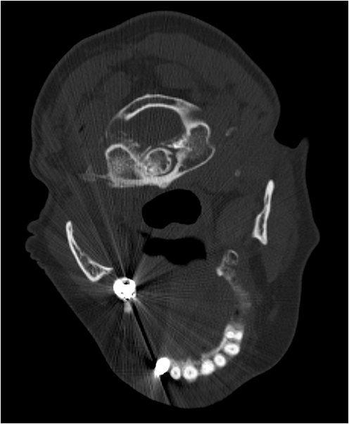 |
Figure 4 Beam hardening and streak artifacts are the main limitations of the CT-guided method compared to fluoroscopy-guided technique. Axial CT images of C1-C2 articulations in a patient with dental amalgam. Technique was adjusted by increasing mAs and kV to reduce streaks and beam hardening artifacts. |
Preprocedural Evaluation
When considering performing a C1-C2 lateral mass articulation injection, several factors must be taken into account. First, the C1-C2 lateral mass articulations should be identified as the probable source of pain based on clinical examination, imaging, and exclusion of alternative diagnoses. Then, it must be decided whether the injection will be performed for diagnostic or therapeutic purposes. Absolute contraindications are the same as those established by the Spine Intervention Society for fluoroscopically guided injections (Table 1).25
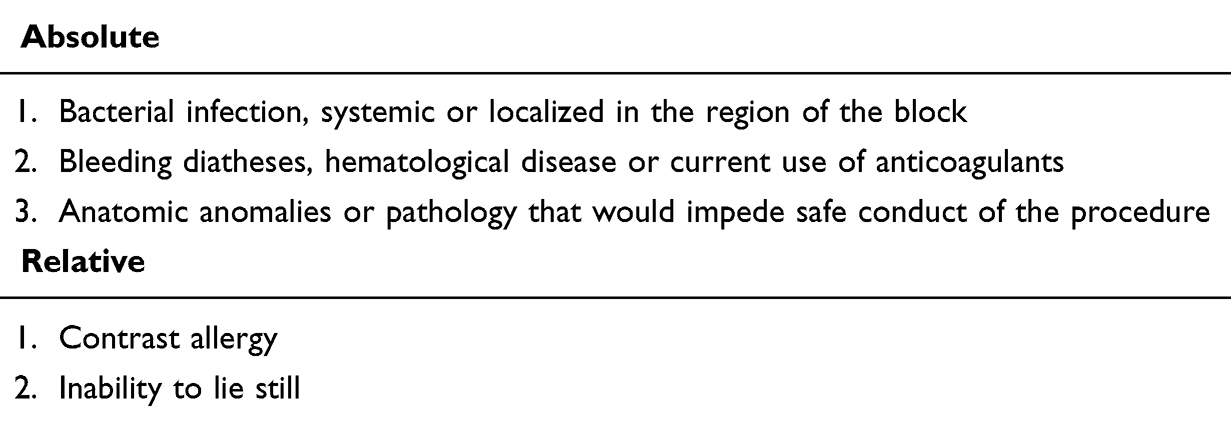 |
Table 1 Contraindications to C1-C2 Lateral Joint CT-Guided Injections |
We discuss the risks, benefits, alternatives, and recovery process associated with this injection with patients as part of obtaining informed consent (Table 2). A review of the patient’s medications and comorbidities should also be performed to ensure proper glycemic control if steroids are used, due to the risk of systemic absorption and effect. Additionally, the use of any anticoagulant medications should be documented and managed to lower the risk of bleeding.
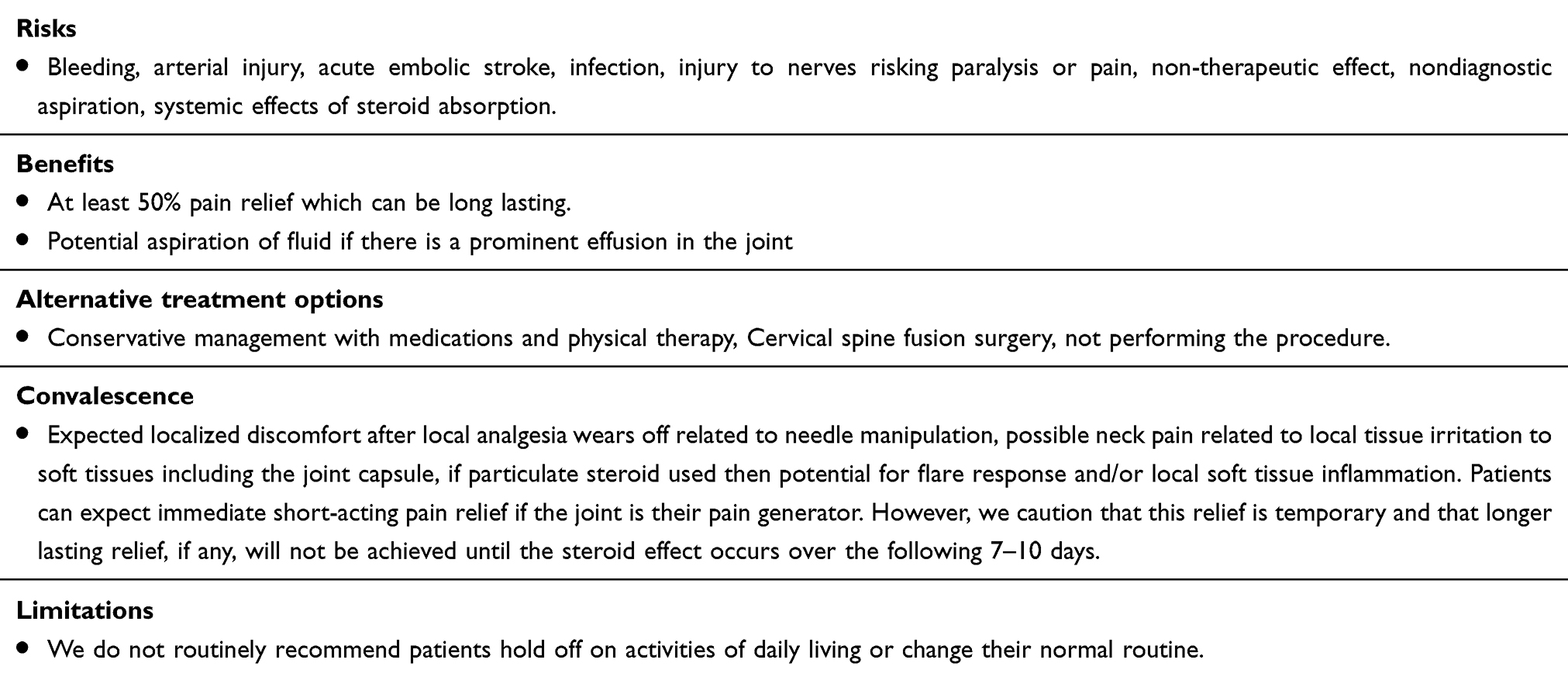 |
Table 2 Risks, Benefits, Alternative Treatment Options, Convalescence, and Post-Procedure Limitations After C1-C2 Lateral Injection |
Injectate Selection
An isolated diagnostic injection may be performed using 1% lidocaine for immediate, short-acting effect or 0.25% bupivacaine, which has a short onset with analgesia lasting approximately 5 hours; there is no literature supporting the preferential use of one over the other. We typically use 1% lidocaine for diagnostic injections because its short-acting effect is preferable in outpatient settings. The literature does not favor any specific steroid for symptomatic relief, and options such as dexamethasone, depot triamcinolone, betamethasone, or methylprednisolone may all be considered. For therapeutic injections, we utilize a combination of 0.5 mL 1% lidocaine and 1 mL dexamethasone 10 mg/mL as the initial treatment. We prefer non-particulate steroids such as dexamethasone in the cervical spine because the risk of intravascular injection of particulate steroids leading to embolization of the brain vasculature is catastrophic, potentially resulting in acute infarct or death.26 If a patient previously had a successful injection with dexamethasone and returns with persistent pain, we will discuss the risks and benefits of attempting a particulate steroid injection, such as triamcinolone-acetate, to achieve longer-lasting pain relief.
Anatomical Proximities & Potential Risks
Prior to reviewing the technical aspects of injection, it is essential to understand the anatomy surrounding the joint to ensure the safest possible trajectory. If any previous imaging is available, the interventionist should review it thoroughly to reduce potential complications. The relevant surrounding anatomy can be considered as follows:
Medially, there is the thecal sac and its contents (Figure 2C), where deviation of the trajectory increases the risk of intrathecal injectate administration, spinal cord or nerve root injury, or CSF leak with pseudomeningocele.
Laterally, the vertebral artery is present and poses a risk of intravascular injection leading to posterior circulation embolization or non-therapeutic injection (Figure 2D). Additionally, if the artery is injured and the patient is on anticoagulation therapy, there is a risk of pseudoaneurysm or catastrophic hemorrhage. It should be noted that the vertebral arteries can have marked variation in size and trajectory, including a course directly along the posterior margin of the joint.27 Therefore, when reviewing any prior cross-sectional imaging, it is important to carefully assess the location and course of the vertebral arteries in relation to the C1-C2 lateral mass articulations.
Ventrally, the internal carotid artery is present, although this is only encountered if the needle is advanced too far anteriorly or through the joint. If this occurs, there is also a risk of extension into the oropharynx. Under fluoroscopic guidance, a lateral image should be checked to ensure the needle has not been inserted too deeply before reaching the posterior joint. During CT guidance, the needle depth should be regularly monitored as the needle is advanced.
Dorsally, along the preferred trajectory for injection, the dorsal root ganglion can be easily encountered at the mid aspect of the joint and is highly sensitive to mechanical stimulation (Figure 2). As is established under fluoroscopic guidance, the CT approach should involve short, intermittent advances with the administration of 1% lidocaine as the needle approaches the posterior margin of the joint, where the dorsal root ganglion (central to medially) or ventral ramus of C2 (more laterally) may be encountered. Lastly, the C2 ventral ramus has variable anatomy and position relative to the joint and might also be located at the dorsal margin of the joint laterally. In addition to the neural structures on the dorsum of the joint, a venous plexus may be present in this area, which should be considered if the patient is at risk for bleeding diathesis.
McNabney et al evaluated 488 contrast-enhanced CTAs of the cervical spine to identify structures that may be encountered during the posterior approach to lateral atlantoaxial joint injections.28 Their study found 7 potential cases in which the vertebral artery and 11 cases in which the thecal sac would likely intersect if a fluoroscopic injection was performed, assuming the thecal sac intersection occurred when the lateral margin of the sac was lateral to the midpoint of the C1-C2 joint.
Patient Positioning
We have our patients lie prone on the CT gantry on a Spine Positioning System II PAD (Oakworks Medical, New Freedom, PA) table support, aiming to maximize patient comfort and maintain a neutral neck position concerning lateral rotation and flexion while limiting motion. Once fiducial markers are placed on the posterior upper neck (craniocaudally oriented radiopaque bars) and scout imaging has been completed, it is crucial to instruct the patient not to move at all, as subsequent marking and initial needle placement depend on the patient remaining in the same position as during scout imaging. Sometimes, the patient’s hair can interfere with keeping the fiducial marker in place, and in such cases, a bonnet can help isolate the hair from the procedural field. In the absence of distortion caused by arthropathy, the path of access to the posterior joint articulation tends to align with the body’s axial plane and the CT images, eliminating the need for gantry tilt. The initial AP and lateral scout images of the cervical spine should include the odontoid to the inferior endplate of the C2 vertebra, both of which should be clearly visible (Figure 5). The procedure is usually performed using a local anesthetic (1% lidocaine). However, if the patient is exceedingly sensitive or anxious, conscious sedation can be beneficial if trained staff and continuous hemodynamic monitoring are available. Note that general anesthesia is not preferred, as the response to the injection should be evaluated shortly after administering the injectate. Additionally, having medication ready for IV analgesia, such as hydromorphone or morphine depending on the patient’s comorbidities, may be helpful.
 |
Figure 5 Patient positioning and scout images. (A) Lateral scout demonstrating the dens, including the C1-C2 lateral mass articulation within the field of view. The initial AP and lateral scout images field of view extends from the odontoid to the inferior endplate of the C2 vertebra. The white dashed line (┋) demarcates the necessary field of view for the procedural CT scan. Note the radiopaque skin marker (white rectangle ▭) adherent to the posterior aspect of the patient’s neck. It is important to ensure that whichever marker is used is properly positioned in the craniocaudal and medial-lateral directions relative to the joint being injected. (B) AP scout covering the mid to upper cervical spine, including the dens. |
CT Image Acquisition
After maintaining the positioning and obtaining a scout image, a preliminary CT scan is performed, including the C1-C2 facet joints. The following settings are used: slice thickness of 1.25 mm, kVp of 120, tube current of 100 mA, focal spot of 1.2, revolution time of 600 ms, and an exposure of 3 mSv. Next, the axial images are reviewed to determine the safest posterior trajectory. A straight line is drawn with a measuring tool from the skin surface on the posterior neck to an unobstructed opening at the posterior atlantoaxial joint to measure the depth of approach and select the appropriate needle length. The trajectory should target the junction of the lateral third and medial two-thirds of the joint (Figure 6). The slice number is documented, and a still image of this slice with markings is saved, indicating where on our fiducial marker the medial/lateral position for the needle puncture site will be marked (usually counting from left or right). Then, a time-out is performed before starting the procedure. (Supplementary data, section 1) Our CT scanner allows sequential acquisition of 3 consecutive slices at variable thicknesses (Smart Step biopsy imaging, 2.5 or 5 mm) centered at the level of interest. Due to the size of the lateral atlantoaxial joint and the tendency for osteophyte formation in degenerative arthrosis, we typically use 2.5 mm slices for this procedure to assist with circumventing any osseous proliferation along the needle trajectory.
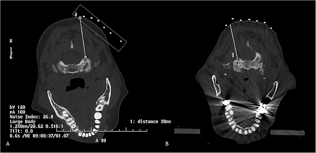 |
Figure 6 Needle trajectory selection. (A) On the initial planning CT scan, a safe trajectory to the posterior aspect of the atlantoaxial joint’s lateral mass articulation is selected, approximately at the junction of the medial two-thirds and lateral one-third of the joint. The fiducial marker indicates the skin entry site between the first and second markers (counting laterally from the midline), showing that the initial needle entry trajectory should have slight lateral angulation. The needle trajectory depth is approximately 5.8 cm, so a 3.5-inch needle is sufficient; if it exceeds 10 cm, a 5-inch needle would be considered, though this is rarely necessary in cervical injections. When approaching the scanner, it is recommended that the interventionalist ensure that the gantry is advanced to the proper position before activating the laser to mark the skin entry site. The initial image is saved, and as long as the patient remains still, they are marked, and the initial needle trajectory is planned based on this image. It is often helpful to visualize the cranio-caudal tilt from the side of the patient and the medial-lateral tilt from the head or foot of the gantry when first placing the needle. The planning CT should be acquired with a 1.25 mm slice thickness, while real-time imaging during biopsy should be set to 2.5 mm slice thickness. Note the radiopaque skin marker (white dashed rectangle ▭) adherent to the posterior aspect of the patient’s neck. (B) An additional example shows needle trajectory selection for the right C1-C2 lateral articulation injection. Note that the dental amalgam and beam hardening or streak artifacts are anterior and do not obscure the field. |
Contrast, Reaction, and Volume
The risks of contrast reactions during CT- guided injections are similar to those in the ACR contrast manual, mainly physiologic/chemotactic and allergic responses.29 Although the likelihood of a contrast reaction is low, patients should be asked if they have had contrast before and if they have experienced any reactions. The total volume of contrast used in the lateral atlanto- axial joint is small (1–2 mL), and the opacification pattern can vary depending on anatomy. The ipsilateral joint will invariably opacify, and in 18% of patients, the pivot joint will communicate centrally, allowing the contralateral lateral atlantoaxial joint to opacify as well.30 Typically, dorsal and ventral joint recesses should be visible and opacified. We usually start by injecting 0.5–1 mL of nonionic monomeric contrast (Omnipaque 180). If the patient reports a contrast allergy, the severity of the reaction must be documented, and the ACR contrast allergy protocol should be followed, including premedication or avoidance of the procedure as needed.29,31 Alternatives to iodinated contrast include air or gadolinium. However, these options must be used judiciously as they have their own inherent risks. If the needle is inadvertently intravascular, an injection of air can result in posterior circulation stroke and as such this must be avoided. Gadolinium- based contrast agents are also used for CT- guided interventions. They differ in density and maintain their own risk profile (eg, nephrogenic systemic fibrosis, systemic deposition, and chemotactic or allergic effects, though they are less allergenic than CT contrast agents.32 Gadavist (gadobutrol) 1 mol/L is the densest contrast for CT, although there are risks of meningitis, encephalitis, and seizures if more than 1–3 mL is injected with intrathecal spread.33 To optimize the k-edge of gadolinium- based contrast agents, adjusting technique- such as reducing kVp to 70- is recommended for maximum opacification. Ideally, CT- fluoroscopy should be used to monitor for contrast extravasation, though step- and- shoot imaging can be performed as well. It is important to obtain a non- opacified image at the same level as the contrast injection to compare pre- and post- contrast images to determine contrast spread (Figure 7).
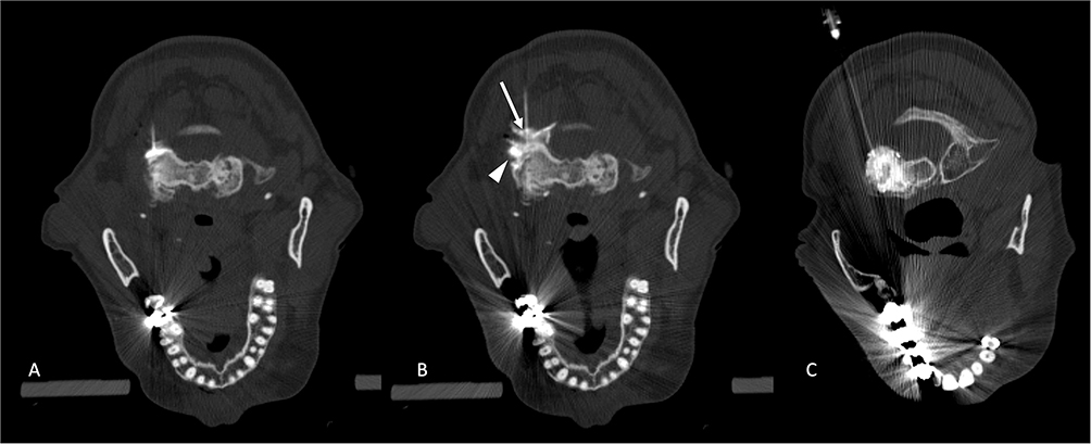 |
Figure 7 Needle insertion, contrast administration, and injection. Axial CT image obtained during C1-C2 lateral mass articulation injection to the left facet joint. (A) Advancement of a 3.5” 22-gauge spinal needle into the posterior aspect of the joint. The trajectory should target the junction of the lateral third and the medial two-thirds of the joint. It is important to note the image position number in case any motion requires gantry repositioning to adequately visualize the needle tip. At this posterior aspect of the C1-C2 lateral mass articulation, the dorsal root ganglion can be encountered. Note the avoidance of the lateral margin of the joint to prevent the vertebral artery. Simultaneously, remaining lateral to the medial aspect of the joint helps avoid the spinal canal. (B) The image illustrates continued administration of intra-articular contrast. Contrast can be administered in 0.5 mL increments until successful opacification of the joint space (arrow ↑) or ventral joint recess (arrowhead ►) is noted. (C) Contrast is seen in the plane of the joint’s articular surface, highlighting the joint space centrally. |
Procedure Tools & Considerations
Our standard procedure kits are stocked with a variety of syringes, needles, and sterile preparatory materials (Table 3). Additionally, we use non-latex sterile gloves and include either a 3.5” 25-gauge or a 3.5” 22-gauge spinal needle. If our initial measured trajectory exceeds 10cm, we opt for a 5” spinal needle instead. Spinal needles are preferred, as both the stylet and cannula have beveled tips, allowing for manipulation and redirection. They are suitable for various purposes, including injection and fluid aspiration. While 25-gauge needles are sufficient for this procedure, we prefer 22-gauge spinal needles as they offer better purchase, tactile feedback, and easier redirection. If osteophytic ridging occurs when attempting to breach the posterior joint capsule, gentle pressure with alternating clockwise and counterclockwise rotation may help traverse osteophytes and access the joint. Some interventionists bend the tip of their needle away from the bevel to allow greater redirection even after soft tissue purchase. Typically, during CT guidance, we do not find this necessary, as staying in the axial plane is easily achieved with a straight needle. Advancing the needle under intermittent CT guidance provides a precise trajectory, with the shadow of the distal tip often reliably guiding the needle’s path. Nonetheless, the spinal needle should be advanced in short increments of 0.5–1 cm, with CT imaging performed between each step to ensure the correct trajectory and avoid critical structures. If access to the C1-C2 lateral mass articulation is required for diagnostic aspiration, a 20-gauge needle may be preferred due to the higher viscosity of the joint aspirate.
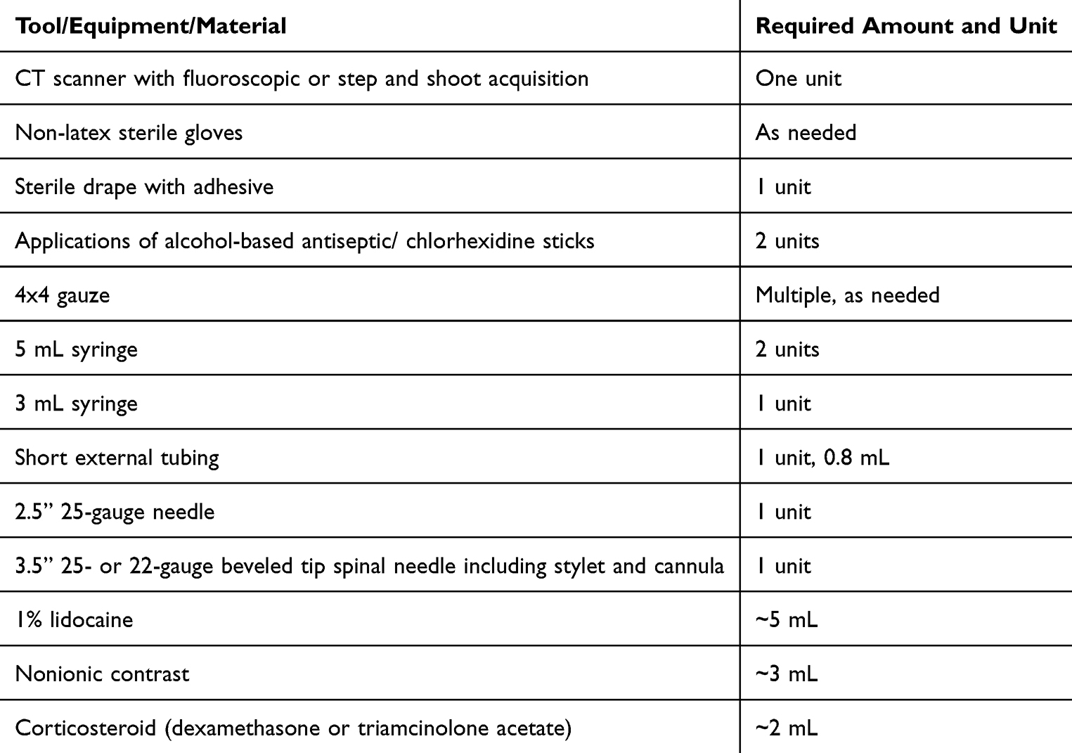 |
Table 3 Required Tools for C1-C2 Lateral Joint Intraarticular Injection |
CT-Guided Injection Technique
The marking laser on the CT is activated when marking the site of needle puncture. It is advisable to count to the fiducial marker of interest closest to the approach and draw two lines: one craniocaudal along the marker closest to the injection site, and the other at 90 degrees to this along the laser marker from medial to lateral. This step should be followed by loading the initial measured trajectory to determine the initial needle angle (Figure 6). The skin over the needle puncture site is sterilized with two chlorhexidine sticks and allowed to dry to establish a sterile field. A drape is then applied. A 25-gauge anesthetic needle is then gently and slowly advanced into the skin, with 1% lidocaine administered gradually as the needle is advanced along the best approximated trajectory, which was initially planned. Slow lidocaine injection is generally better tolerated than forceful injection. It is helpful to look at the needle from the side of the patient and from the foot of the gantry, as remaining in plane with the CT acquisition is best achieved utilizing two planes. The patient is then advanced back into the machine at the level of the injection, ensuring the crosshair is on top of the needle hub. Next, it is recommended to acquire another sequence of three images, noting their positions. If the trajectory of the anesthetic needle is satisfactory, the 25-gauge needle can be exchanged for a 3.5-inch 22-gauge spinal needle in tandem, unless the exact entry point is precisely marked. The same trajectory should be maintained, and the needle advanced approximately 2 cm or until adequate tissue purchase is achieved. The patient is again positioned in the CT scanner at the level of previous needle placement, with the laser on the scanner to confirm positioning directly over the needle hub. The ideal trajectory is in-plane in a single slice; however, if the needle is tilted or angled, cross-cutting will occur. If one image slice shows part of the needle and the next slice does not, it may indicate that the needle tip is not visible. The next step involves examining the image location number on the slice where the needle’s distal end appears and adjusting the gantry to center the laser over or just beyond this slice. This process should continue until the clinician is confident in the needle position, then the needle should be adjusted and advanced by gripping its hub or the uppermost part until reaching the posterior aspect of the joint at the junction of the lateral third and medial two-thirds. As mentioned, the dorsal root ganglion may be encountered, and administering 0.3 mL of lidocaine at the joint’s posterior margin can help prevent pain from accidental contact with the ganglion (Figure 8). Once at the joint capsule, a slight change in tactile feedback can be helpful, and a short length of external tubing (0.8 mL) primed with contrast can be attached to facilitate an arthrogram (Figure 7 and Supplementary video). Slowly injecting about 0.5 mL of contrast—less than 1 mL usually suffices to opacify the dorsal recess, ventral recess, or articular portion of the joint. Since the joint’s volume is limited (2–3 mL), it is best to reserve the space for the injectate. Approximately 1 mL of steroid can then be injected, followed by 0.5 mL of lidocaine. Care must be taken not to inject against perceived resistance in the joint during administration of the injectate, as this can rupture the joint capsule can result in extravasation beyond the joint (Figure 9B). In patients with advanced disease, the joint capsule may be inherently deficient, allowing contrast to spread to adjacent regions (Figure 9C). Several notable, non-conventional, or complex cases are reviewed in Figure 9.
 |
Figure 8 Axial CT image obtained during injection of the left C1-C2 lateral mass articulation demonstrates periarticular opacification, highlighting the C2 dorsal root ganglion. |
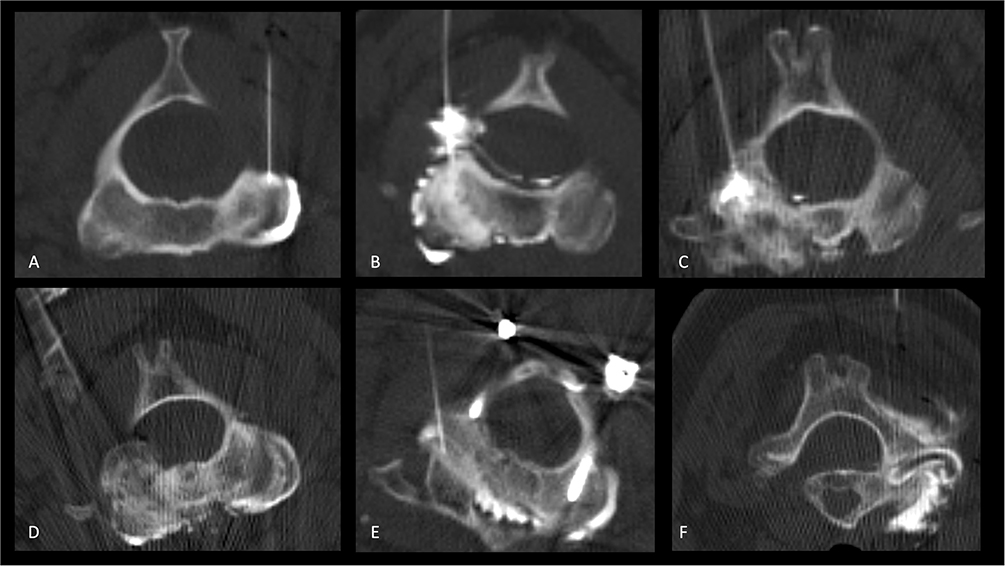 |
Figure 9 Notable, non-conventional, or complex cases of axial CT images obtained during arthrogram of the left C1-C2 lateral mass articulation. (A) Axial CT image visualizing normal contrast opacifying the lateral joint extending to the ventral joint recess. (B) Opacification of the articular surface with contrast extending into the ventral joint recess. There is also extracapsular spread of contrast, notably into the ventral epidural space. This emphasizes the importance of exercising caution when using an anesthetic for this injection and the preference for 1% lidocaine, as there is a theoretical risk of high anesthesia causing motor palsy and respiratory paralysis. (C) Opacification of a severely arthritic joint, with focal extracapsular spread of contrast to the ventral epidural space. (D) Opacification of the left lateral mass articulation with contrast extending across the anterior arch dens articulation into the left lateral mass. Also noted is contrast extending beyond the dorsal joint capsule into the adjacent soft tissues. The injection proceeded despite the risk of some extra-capsular extension of injectate, as periarticular with partial intra-articular injections can provide symptomatic relief. (E) Beam hardening and streak artifacts are the main limitations of the CT-guided method compared to fluoroscopy-guided techniques. Axial CT images were acquired in a patient with a history of upper cervical spine posterior arthrodesis. The facet joints were at the level adjacent to the hardware, resulting in altered mechanics and contributing to advanced degeneration. The technique was adjusted by increasing mAs and kV to reduce streak and beam hardening artifacts. Contrast is noted to communicate across the left facet joint, across the anterior arch-dens articulation, and into the left facet joint. In this patient, 1 mL of contrast, which opacified both joints, was administered. (F) Axial CT image during injection of the right C1-C2 lateral mass articulation shows contrast extending beyond the joint capsule into the ventral and dorsal soft tissues, as well as along the course of the vertebral artery into the foramen transversarium. Although most of the contrast remains at and around the joint, there is a potential risk that the injectate could be carried into a venous plexus surrounding the vertebral artery. Arterial opacification is notably absent, however. |
Conclusion
In summary, C1-C2 lateral mass injections have been established as facilitating temporary relief from cervicogenic headache symptoms. The delicate anatomy surrounding the C1-C2 joint allows for only a limited safe trajectory, with a narrow target area at the posterior joint line for intra-articular access. These injections are most effectively performed using image guidance. It is crucial for the performing interventionalist to be cognizant of the anatomy and be aware of the potentially encountered structures, potential complications, and pitfalls when performing these injections. At the time of preparation of this manuscript, our institution has experience with 103 CT-guided injections performed without adverse events. Therefore, when performed properly, these injections can be safely administered under CT guidance.
Highlights
- Critical Anatomical Understanding: Accurate knowledge of the C1-C2 joint anatomy and its innervation is vital for performing image-guided injections safely and avoiding complications.
- Technique Refinement: CT guidance provides better visualization and accuracy than fluoroscopy, enhancing the safety and effectiveness of C1-C2 lateral joint injections and C2 ganglion ablations.
- Risk Mitigation: Recognizing and addressing potential pitfalls, such as intravascular injections and nerve damage, is essential for achieving successful outcomes in these procedures.
Disclosure
Dr John Carrino reports personal fees from Covera, personal fees from AstraZeneca, personal fees from Globus, outside the submitted work. Dr Michael Schatman reports other from Apurano Pharma, outside the submitted work. Dr Edward Yoon reports personal fees from Neurovasis, outside the submitted work. The Authors disclose no conflict of interest related to this work.
References
1. Haldeman S, Dagenais S. Cervicogenic headaches: a critical review. Spine J. 2001;1(1):31–46. doi:10.1016/s1529-9430(01)00024-9
2. Sjaastad O, Saunte C, Hovdahl H, Breivik H, Grønbâk E. “Cervicogenic” headache. An hypothesis. Cephalalgia. 1983;3(4):249–256. doi:10.1046/j.1468-2982.1983.0304249.x
3. Bogduk N, Govind J. Cervicogenic headache: an assessment of the evidence on clinical diagnosis, invasive tests, and treatment. Lancet Neurol. 2009;8(10):959–968. doi:10.1016/S1474-4422(09)70209-1
4. Sjaastad O. Cervicogenic headache: comparison with migraine without aura; Vågå study. Cephalalgia. 2008;28(SUPPL. 1):18–20. doi:10.1111/j.1468-2982.2008.01610.x
5. Bogduk N. The neck and headaches. Neurol Clin. 2004;22(1):151–171. doi:10.1016/s0733-8619(03)00100-2
6. Aprill C, Axinn MJ, Bogduk N. Occipital headaches stemming from the lateral atlanto-axial (C1-2) joint. Cephalalgia. 2002;22(1):15–22. doi:10.1046/j.1468-2982.2002.00293.x
7. Ehni G, Benner B. Occipital neuralgia and the C1-2 arthrosis syndrome. J Neurosurg. 1984;61(5):961–965. doi:10.3171/jns.1984.61.5.0961
8. McCormick CC. Arthrography of the atlanto-axial (C1-C2) joints: techniques and results. J Interv Radiol. 1987;2(1):9–13.
9. Busch E, Wilson PR. Atlanto-occipital and atlanto-axial injections in the treatment of headache and neck pain. In: Regional Anesthesia. Vol. 14. BMJ Publishing Group Ltd; 1989:45.
10. Paluzzi A, Belli A, Lafuente J, Wasserberg J. Role of the C2 articular branches in occipital headache: an anatomical study. Clin Anat. 2006;19(6):497–502. doi:10.1002/ca.20206
11. Yin W, Willard F, Dixon T, Bogduk N. Ventral innervation of the lateral C1-C2 joint: an anatomical study. Pain Med. 2008;9(8):1022–1029. doi:10.1111/j.1526-4637.2008.00493.x
12. Dreyfuss P, Michaelsen M, Fletcher D. Atlanto-occipital and lateral atlanto-axial joint pain patterns. Spine. 1994;19(10):1125–1131. doi:10.1097/00007632-199405001-00005
13. Zapletal J, De Valois JC. Radiologic prevalence of advanced lateral C1-C2 osteoarthritis. Spine. 1997;22(21):2511–2513. doi:10.1097/00007632-199711010-00009
14. Harata S, Tohno S, Kawagishi T. Osteoarthritis of the atlanto-axial joint. Int Orthop. 1982;5(4):277–282. doi:10.1007/bf00271083
15. Halla JT, Hardin JG. Atlantoaxial (C1‐C2) facet joint osteoarthritis: a distinctive clinical syndrome. Arthritis Rheum. 1987;30(5):577–582. doi:10.1002/art.1780300514
16. Schaeren S, Jeanneret B. Atlantoaxial osteoarthritis: case series and review of the literature. Eur Spine J. 2005;14(5):501–506. doi: 10.1007/s00586-004-0856-4
17. Antonaci F, Ghirmai S, Bono G, Nappi G, Sandrini G. Cervicogenic headache: evaluation of the original diagnostic criteria. Cephalalgia. 2001;21(5):573–583. doi:10.1046/j.0333-1024.2001.00207.x
18. Verma S, Tripathi M, Chandra P. Cervicogenic Headache: current Perspectives. Neurol India. 2021;69(7):S194–8. doi:10.4103/0028-3886.315992
19. Racicki S, DiClaudio S, Reinmann S, Gerwin S, Donaldson M. Conservative physical therapy management for the treatment of cervicogenic headache: a systematic review. J Man Manip Ther. 2013;21(2):113–124. doi:10.1179/2042618612Y.0000000025
20. Fung M, Frydenberg E, Barnsley L, Chaganti J, Steel T. Clinical and radiological outcomes of image guided posterior C1-C2 fixation for atlantoaxial osteoarthritis (AAOA). J Spine Surg. 2018;4(4):725–735. doi:10.21037/jss.2018.12.04
21. Ghanayem AJ, Leventhal M, Bohlman HH. Osteoarthrosis of the atlanto-axial joints. Long-term follow-up after treatment with arthrodesis. J Bone Jt Surg. 1996;78(9):1300–1307. doi:10.2106/00004623-199609000-00002
22. Joseph B, Kumar B. Gallie’s fusion for atlantoaxial arthrosis with occipital neuralgia. Spine. 1994;19(4):454–455. doi:10.1097/00007632-199402001-00013
23. Narouze SN, Casanova J, Mekhail N. The longitudinal effectiveness of lateral atlantoaxial intra-articular steroid injection in the treatment of cervicogenic headache. Pain Med. 2007;8(2):184–188. doi:10.1111/j.1526-4637.2006.00247.x
24. Raposio G, Raposio E. Surgical therapy of occipital (Arnold) neuralgia: a case series. Ann Med Surg. 2022;80:104237. doi:10.1016/j.amsu.2022.104237 PMID: 36045775; PMCID: PMC9422306.
25. Bogduk N. Practice Guidelines for Spinal Diagnostic and Treatment Procedures. International Spine Intervention Society; 2013.
26. Edlow BL, Wainger BJ, Frosch MP, Copen WA, Rathmell JP, Rost NS. Posterior circulation stroke after C1-C2 intraarticular facet steroid injection: evidence for diffuse microvascular injury. Anesthesiology. 2010;112(6):1532–1535. doi:10.1097/aln.0b013e3181d7b15a
27. Sharma RR, Parekh HC, Prabhu S, Gurusinghe NT, Bertolis G. Compression of the C-2 root by a rare anomalous ectatic vertebral artery: case report. J Neurosurg. 1993;78(4):669–672. doi:10.3171/jns.1993.78.4.0669
28. McNabney C, Chavda A, Alabsi H, Sellers SL, Murphy DT, Fenton D. Anatomic considerations for injection of the lateral atlanto-axial joint. Pain Med. 2019;20(11):2115–2119. doi:10.1093/pm/pnz137
29. Cohan RH, Dillman JR, Hartman RP, et al. American college of radiology manual on contrast media version 9 ACR manual on contrast media. Am Coll Radiol. 2013;9:45–50.
30. Chevrot A, Cermakova E, Vallée C, et al. C1-2 arthrography. Skeletal Radiol. 1995;24(6):425–429. doi:10.1007/bf00941238
31. Beckett KR, Moriarity AK, Langer JM. Safe use of contrast media: what the radiologist needs to know. Radiographics. 2015;35(6):1738–1750. doi:10.1148/rg.2015150033
32. Maus TP, Schueler BA, Magnuson DJ, Magnuson D. Relative conspicuity of gadolinium-based contrast agents in interventional pain procedures. Pain Med. 2017;18(4):651–654. doi:10.1093/pm/pnw312
33. Popescu A, Patel J, McCormick ZL, et al. Fact finders for patient safety: are gadolinium-based contrast media safe alternatives to iodinated contrast agents for the safe performance of spinal injection procedures? Pain Med. 2018;19(10):2089–2090. doi:10.1093/pm/pny090
 © 2025 The Author(s). This work is published and licensed by Dove Medical Press Limited. The
full terms of this license are available at https://www.dovepress.com/terms
and incorporate the Creative Commons Attribution
- Non Commercial (unported, 4.0) License.
By accessing the work you hereby accept the Terms. Non-commercial uses of the work are permitted
without any further permission from Dove Medical Press Limited, provided the work is properly
attributed. For permission for commercial use of this work, please see paragraphs 4.2 and 5 of our Terms.
© 2025 The Author(s). This work is published and licensed by Dove Medical Press Limited. The
full terms of this license are available at https://www.dovepress.com/terms
and incorporate the Creative Commons Attribution
- Non Commercial (unported, 4.0) License.
By accessing the work you hereby accept the Terms. Non-commercial uses of the work are permitted
without any further permission from Dove Medical Press Limited, provided the work is properly
attributed. For permission for commercial use of this work, please see paragraphs 4.2 and 5 of our Terms.
Recommended articles
The American Society of Pain and Neuroscience (ASPN) Guidelines for Advanced Practice Providers in Interventional Spine and Pain Management Practice
Grillo C, Abd-Elsayed A, Yousef TA, Misercola B, Hussaini Z, Rabii M, Comer A, Durkin K, McGinn P, Deer T
Journal of Pain Research 2025, 18:6319-6344
Published Date: 26 November 2025