Back to Journals » International Journal of Nanomedicine » Volume 16
Magnetic Particle Imaging: In vitro Signal Analysis and Lumen Quantification of 21 Endovascular Stents
Authors Wegner F ![]() , von Gladiss A
, von Gladiss A ![]() , Haegele J, Grzyska U
, Haegele J, Grzyska U ![]() , Sieren MM
, Sieren MM ![]() , Stahlberg E
, Stahlberg E ![]() , Oechtering TH
, Oechtering TH ![]() , Lüdtke-Buzug K, Barkhausen J
, Lüdtke-Buzug K, Barkhausen J ![]() , Buzug TM
, Buzug TM ![]() , Friedrich T
, Friedrich T
Received 1 October 2020
Accepted for publication 11 December 2020
Published 11 January 2021 Volume 2021:16 Pages 213—221
DOI https://doi.org/10.2147/IJN.S284694
Checked for plagiarism Yes
Review by Single anonymous peer review
Peer reviewer comments 2
Editor who approved publication: Professor Israel Rubinstein
Franz Wegner,1,* Anselm von Gladiss,2,* Julian Haegele,1,3 Ulrike Grzyska,1 Malte Maria Sieren,1 Erik Stahlberg,1 Thekla Helene Oechtering,1 Kerstin Lüdtke-Buzug,2 Joerg Barkhausen,1 Thorsten M Buzug,2,4 Thomas Friedrich2,4
1Department of Radiology and Nuclear Medicine, University of Lübeck, Lübeck, Germany; 2Institute of Medical Engineering, University of Lübeck, Lübeck, Germany; 3Zentrum für Radiologie und Nuklearmedizin Rheinland, Dormagen, Germany; 4Fraunhofer Research Institution for Individualized and Cell-Based Medical Engineering, Lübeck, Germany
*These authors contributed equally to this work
Correspondence: Franz Wegner
University Hospital Schleswig-Holstein, Campus Lübeck, Department of Radiology and Nuclear Medicine, Ratzeburger Allee 160, Lübeck 23538, Germany
Tel +004945150017001
Fax +004945150017004
Email [email protected]
Purpose: Endovascular stents are medical devices, which are implanted in stenosed blood vessels to ensure sufficient blood flow. Due to a high rate of in-stent re-stenoses, there is the need of a noninvasive imaging method for the early detection of stent occlusion. The evaluation of the stent lumen with computed tomography (CT) and magnetic resonance imaging (MRI) is limited by material-induced artifacts. The purpose of this work is to investigate the potential of the tracer-based modality magnetic particle imaging (MPI) for stent lumen visualization and quantification.
Methods: In this in vitro study, 21 endovascular stents were investigated in a preclinical MPI scanner. Therefore, the stents were implanted in vessel phantoms. For the signal analysis, the phantoms were scanned without tracer material, and the signal-to-noise-ratio was analyzed. For the evaluation of potential artifacts and the lumen quantification, the phantoms were filled with diluted tracer agent. To calculate the stent lumen diameter a calibrated threshold value was applied.
Results: We can show that it is possible to visualize the lumen of a variety of endovascular stents without material induced artifacts, as the stents do not generate sufficient signals in MPI. The stent lumen quantification showed a direct correlation between the calculated and nominal diameter (r = 0.98).
Conclusion: In contrast to MRI and CT, MPI is able to visualize and quantify stent lumina very accurately.
Keywords: magnetic particle imaging, endovascular stents, artifacts, superparamagnetic iron oxide nanoparticles, lumen quantification
Introduction
Magnetic Particle Imaging (MPI) is a three-dimensional tracer-based imaging modality.1 The main principle of MPI is the visualization of the distribution of superparamagnetic iron oxide nanoparticles (SPIONs) with oscillating magnetic fields. MPI offers a very high temporal and a high spatial resolution without tissue attenuation of the signal. Furthermore, it is a very sensitive imaging modality with the ability to detect only 192 pg of iron.2 In addition, the possibility of real-time imaging with the absence of ionizing radiation and nephrotoxic contrast agents renders MPI a very promising imaging method.3 In the last decade, several studies demonstrated the potential of MPI for cardiovascular imaging and vascular interventions.3–8 Most recently the proof of principle of MPI guided stent implantations and first safety measurements of stents became available.9,10
Stent implantation is becoming increasingly common in clinical routine and interventional radiology and cardiology are steadily replacing surgical procedures. However, there is a significant risk of in-stent re-stenosis after stent implantation.11 To prevent recurrent ischemic events like heart attacks or strokes an early noninvasive detection of in-stent stenosis has an extremely high clinical impact. Unfortunately, the visualization of the stent lumen with clinically established noninvasive imaging modalities CT and MRI is limited due to material induced artifacts.12,13 In MRI susceptibility artifacts cause severe signal voids which strictly limit the noninvasive assessment of the stent lumen. In CT beam-hardening effects result in a thickening of the displayed stent struts which also inhibits a sufficient lumen evaluation, especially in stents with smaller diameters. In recent years, artifact reduction algorithms got established and it has been shown, that stent induced artifacts are less evident in dual energy CT.14,15 Nevertheless, as an artifact-free noninvasive imaging method for the early detection of stent thromboses or high grade in-stent stenoses is still not available, the majority of patients are referred as emergencies into the clinic when ischemic symptoms occur. In these cases, only invasive imaging with x-ray-based digital subtraction angiography (DSA) offers both, the possibility to diagnose and treat the stent occlusion free of material-induced artifacts. However, first pilot results suggest MPI may overcome this disadvantage by allowing noninvasive artifact free stent lumen visualization in comparison with MRI and CT.16 MPI’s spatial resolution (<1 mm) is comparable to CT and MRI.17 The acquisition time (per frame) is in the range of milliseconds and thus MPI is much faster than the established modalities.
Thus far MPI has only found preclinical utilization though first scanners have recently become available allowing in vivo application on humans.18 Given a potential clinical use of MPI, the quantification of the vascular lumen is of great interest to detect hemodynamically relevant stenoses. Based on the quantitative characteristic of MPI,19 Vaalma et al and Herz et al previously demonstrated the potential of lumen quantification with MPI in the absence of interventional devices or stents.7,20 However, as metallic objects and thus, in principle, even stents are able to generate MPI signals,21 the potential of lumen quantification in the presence of endovascular stents needs to be proven. In addition to signal attenuation, there may also be strengthening artifacts which could influence the visualization and quantification of the stent lumen.
The aim of this phantom study was to analyze the signal characteristics of endovascular stents, to investigate potential material induced effects on stent lumen visualization in MPI, and to explore the potential of stent lumen quantification.
Materials and Methods
Stents and Phantoms
In this study 21 commercially available endovascular stents were investigated (Table 1). The tested stents had diameters between 3 and 10 mm, a length of 11 to 99 mm and were made from different materials (stainless steel = 316L, nitinol, platinum-chromium = PtCr, cobalt-chromium = CoCr). All stents were implanted in silicone tubes corresponding to their nominal diameter. The inner diameter of the phantoms has been exemplarily validated by means of mechanical measurement. For imaging, the phantoms (stented phantoms and non-stented reference phantoms) were filled with diluted tracer material (Figure 1). In all experiments, we used the MRI contrast agent Resovist (I’rom Pharmaceuticals, Tokyo, Japan) as MPI tracer, diluted with deionized water.
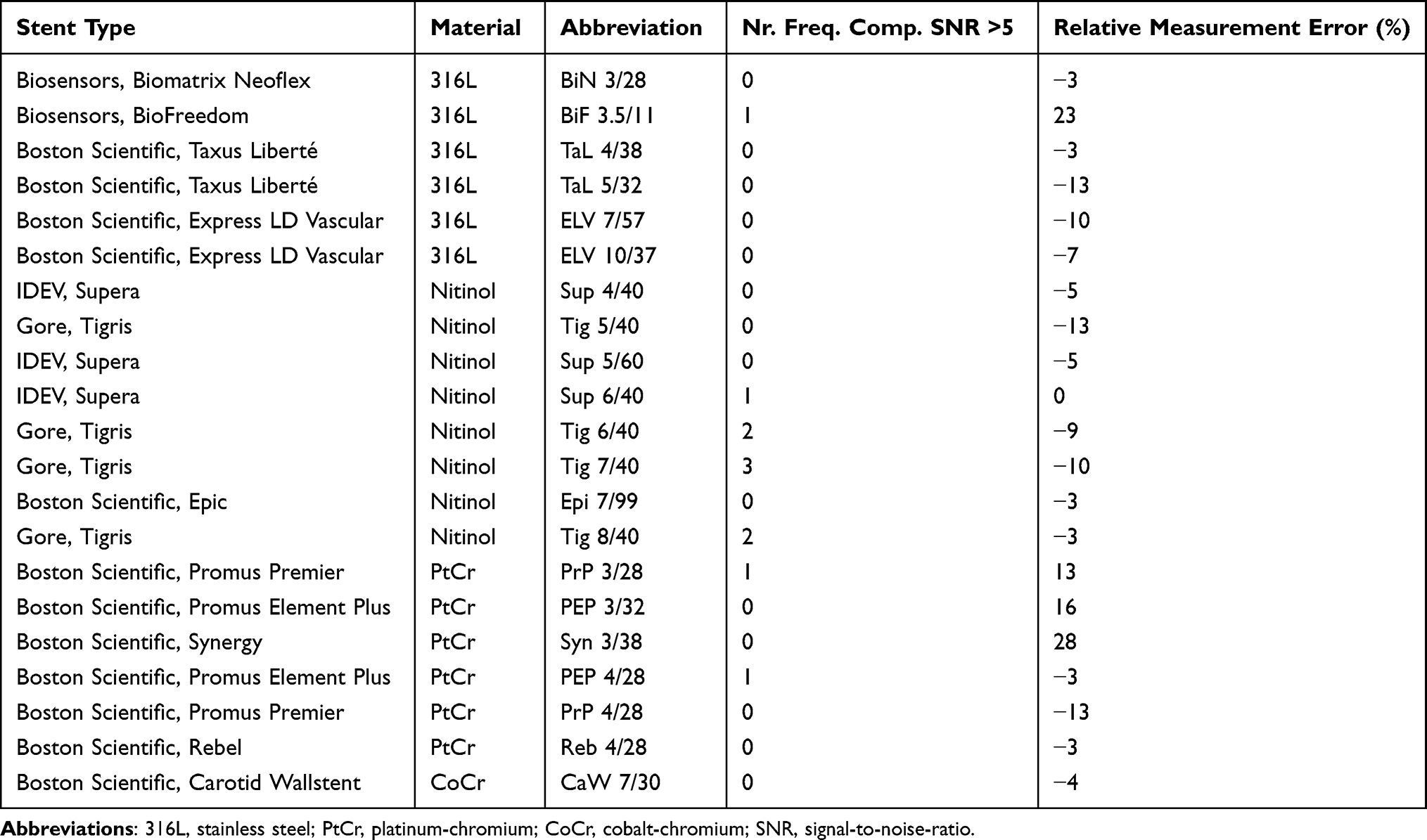 |
Table 1 Detailed Information of the Investigated Stents Including Stent Type, Material, Abbreviation (First Letters of Stent Name, Diameter/Length in mm), Number of Frequency Components Generated by the Stents and Relative Measurement Error of the Lumen Quantification (Calculated vs Nominal Lumen Diameter) |
 |
Figure 1 Image of a reference phantom (top) and a stented vessel phantom (bottom, Taxus Liberté 5/32), both filled with tracer dilution (1:100, Resovist, I’rom Pharmaceuticals, Tokyo, Japan). The stented phantom has a slightly curved shape caused by the storage of the phantoms as wound tubes. For imaging, all phantoms were straightly aligned on a dedicated phantom holder. |
MPI Setup
All measurements were performed using a preclinical commercially available MPI system (MPI 25/20FF, Bruker, Ettlingen, Germany). The MPI scanner works with a field-free-point approach. Excitation frequencies were 24.5 kHz, 26.0 kHz, and 25.3 kHz in x-, y-, and z-direction, respectively. The excitation field strengths were 12 mT in each direction. For the signal characterization measurements of the stents a selection field gradient of 0.4 T/m (z-direction) and 0.2 T/m (x- and y-direction) was applied to ensure covering the whole stent volume. To achieve an appropriate spatial resolution (0.485 mm in z-direction, 0.970 mm in x- and y-direction) imaging measurements were performed with a selection field gradient of 2 T/m in z-direction and of 1 T/m in x- and y-direction, resulting in a FOV of 24 mm x 24 mm x 12 mm, covering the central part of the stents. The duration of one excitation cycle was 21.54 ms. To ensure the best possible imaging quality all measurements were averaged over 1000 repetitions of the drive field cycle, resulting in a measurement time per scan of 21.54 s. The phantoms were placed in the center of the MPI scanner on a self-constructed nonmagnetic phantom holder aligned along the x-axis of the scanner by a positioning robot.
Image Reconstruction
Image reconstruction was realized with a hybrid system matrix approach and a Kaczmarz algorithm in Matlab.17,22,23
In order to cope with possible artifacts from particles outside of the FOV, the system matrix covered a FOV of 32 mm x 32 mm x 16 mm and therefore, included an overscan.24 The following reconstruction parameters were chosen: frequency-range 75 kHz to 600 kHz, SNR-threshold: 250, regularization factor: 8, number of iterations: 1.
Data Analysis
The measurements for the signal characterization of stents were performed with stented vessel phantoms without tracer material and a reference phantom solely filled with tracer dilution (1:100). The signal-to-noise-ratio (SNR) of the spectral data of the stent measurements was calculated for estimating the influence of the stents on the receive signal (Figure 2). A measurement with an empty bore was subtracted of each measurement correcting for the background signal of the MPI setup. The noise level of the MPI setup was determined by averaging over 41 additional background-corrected empty measurements and adding the standard deviation of these measurements, which takes the dynamic part of the background signal into account.
 |
Figure 2 SNR of the frequency components generated by the stents (without tracer) and the tracer dilution (Resovist). The majority of frequency components generated by the stents was below the threshold of SNR=5 (colored lines). Only up to three single frequency components (per stent) were above the chosen threshold value (colored cross markers). |
In order to estimate the lumen diameter, the signal intensity profiles in z-direction of the reconstructed images (xz-plane of MIPs) were analyzed (Figure 3). As the full width at half maximum (FWHM) criterion did not produce valid results, a different signal level criterion – full width at X maximum (FWXM) was calibrated using all the stent and reference measurements (Figure 4). “X” means that the percentage of the maximum used as threshold is variable and was calculated for each phantom individually. The calibrated common global FWXM was reapplied on the signal intensity profiles to determine the error between the calculated and nominal phantom diameter (Figure 5, Table 1). Here, the given, exemplarily validated diameter of the silicon tubes was used. For calibration of the FWXM 11 central signal intensity profiles were used of each measurement (Figure 3). Outer profiles were omitted in order to avoid edge artifacts.20 The signal intensity profiles were interpolated linearly to a higher grid of 33,000 data points for minimizing numerical errors when calibrating the FWXM. Then, the FWXM for each signal intensity profile was determined by the smallest relative signal level that incorporates a number of data points corresponding to the nominal diameter of the phantoms. An average FWXM was calculated for each stent and reference measurement (Figure 4). Furthermore, a global FWXM was determined by averaging the single FWXMs. The global FWXM was reapplied on the signal intensity profiles of each measurement for estimating the lumen diameter. Again, only the 11 central signal intensity profiles were used and the single calculated diameters were averaged (Figures 3 and 5).
 |
Figure 3 Signal intensity profiles of 11 central slices which were used for data analysis are exemplarily shown for the Taxus Liberté 5/32. |
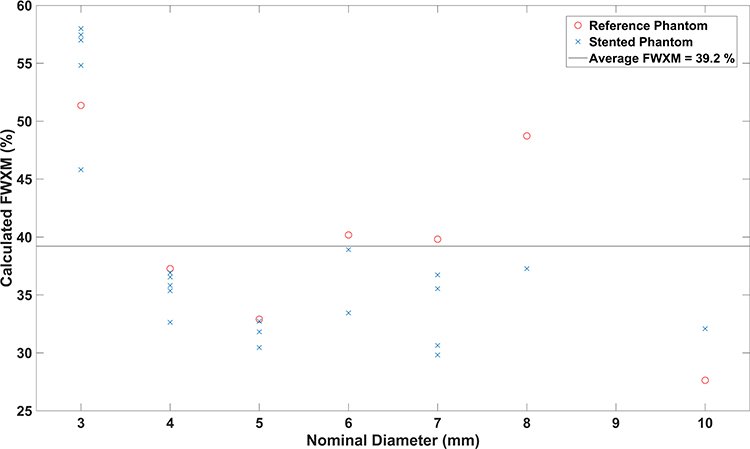 |
Figure 4 Calculated FWXM (X=39.2%) for all phantoms. This value was chosen to distinguish between phantom lumen and surrounding in this work. |
 |
Figure 5 Calculated and nominal lumen diameter of all phantoms. Pearson’s correlation coefficient described the correlation of both with a value of r=0.98. |
Statistics
To describe the correlation between the measured diameters of the reference phantoms and the stented phantoms Pearson’s correlation coefficient (r) was calculated.25 Furthermore, the relative measurement error of the calculated diameters of all phantoms was computed. The overall inaccuracy of lumen quantification was determined by computing the root mean square error for all stented and reference phantoms.
Results
Signal Characterization
The spectrum of Resovist had 435 frequency components above a threshold of SNR=5 (Rose-criterion).26 The frequency components of the MPI signal of 14 stents were below this threshold (Figure 2). Up to three single frequency components per stent could be assigned to seven of the 21 tested stents (Figure 2, Table 1).
Phantom Imaging
All phantoms were visualized with MPI. The xz-planes of all reconstructed images are displayed as Maximum Intensity Projections (MIPs) in Figure 6. There was no visual difference between the images of the reference phantoms and the stented phantoms. In the periphery of all phantoms symmetrical artifacts occurred. Those artifacts had a lower intensity compared to the phantom signal. There was no difference regarding the number of artifacts for reference and stented vessel phantoms. All phantoms appeared conical at the edges of the field of view (FOV). With increasing diameter these effects increased, which resulted in an oval shape of the phantoms with diameters of more than 5 mm. The central regions of the phantoms were not influenced. A second phenomenon occurring with increasing phantom diameter was a small symmetrical signal attenuation, which excluded the centers of the reconstructed images (eg Ref 8, Figure 6). In all images, the central transversal 11 rows (see Figure 6) were unaffected by these effects.
 |
Figure 6 MPI images (MIP of xz-planes) of all stented phantoms and a corresponding reference phantom for each diameter. There was no visual difference between the stented phantoms and the reference phantoms. Artifacts at the ends of the stents were increasing with increasing phantom diameter. |
Stent Lumen Quantification
The calculated FWXM values of the phantoms varied between 28% and 58% (Figure 4) which only corresponds to a small deviation of the diameter due to the high slope of the signal intensity curve (Figure 3). The global FWXM was 39.2% (Figure 4). This value was defined as the threshold between lumen and surrounding of the phantoms in this work. There was a higher FWXM threshold for phantoms featuring a silicon tube of 3 mm. The reference phantoms had slightly higher FWXM values than the stented phantoms.
Based on the average of the FWXM values a signal intensity of 39.2% was chosen for the quantification of the phantoms’ luminal diameter. There was a direct correlation between the calculated and nominal diameter (stented phantoms r = 0.979, reference phantoms: r = 0.983) (Figure 5). Except for the 3 mm phantoms, there was no or only a small underestimation of the luminal diameter of all phantoms (Figure 5, Table 1). The root mean square (RMS) inaccuracy of the calculated diameter was 0.19 mm for the reference phantoms and 0.22 mm for the stented phantoms. Thus, the difference of the measurements between stented and reference phantoms was lower than the half of a voxel size (0.485 mm/2 = 0.243 mm).
Discussion
Our study carries two messages we believe to be important: endovascular stents do not generate sufficient MPI signal for imaging and thus, the stent lumen can be depicted without material induced artifacts. Secondly, MPI allows for accurate quantification of the stent lumen.
In principle, MPI depicts the spatial distribution of SPIONs, as it is a tracer-based method. Since many medical implants and instruments are ferromagnetic, the potential of material induced artifacts in MPI has to be acknowledged. Haegele et al investigated spectra of interventional catheters and guidewires in MPI and concluded that there are signal and non-signal generating devices.21 In our study, we cannot confirm these results for stents. As there is no MPI-specific threshold, we applied the Rose-criterion to define the threshold for sufficient MPI signal.26 Most of the frequency components generated by the stents in the MPI raw data were below an SNR of 5. There were only few frequency components (max. 3) that could be addressed to single stents. To reconstruct an MPI image, a spectrum of higher harmonic frequencies is needed.1,27 In our work, the small number of frequency components was randomly distributed and therefore it can be assumed that it is not significant for image reconstruction. This is confirmed by the visual comparison of the MPI images and the almost identical correlation coefficients (stented phantoms/reference phantoms vs nominal diameter). A recently published multimodality study proposed MPI to overcome material induced artifacts of coronary stents in MRI and CT.16 Our study proves the potential of artifact free stent lumen imaging with MPI, based on the signal characteristics of stents with a wide range of different diameters and materials. Although stents do not generate MPI signal and therefore do not cause material induced artifacts, a number of general artifacts requires discussion. First, previous studies observed a signal loss and conical shape in the periphery of the reconstructed images, especially when the scanned object exceeded the FOV.20 In relation to the limited MPI FOV, this effect limits the imaging accuracy and is observed in our experiments, too. For these artifacts, which are caused by the limited FOV of the used MPI system, multi-patch imaging could be a sufficient approach.28 To exclude any influence of this effect on our data, we only used the central slices of the images for the quantitative analysis. Secondly, the imaging accuracy depended on the positioning of the phantom in the FOV. We expect this effect to be caused by the hybrid approach of image reconstruction. Thus, a comparison of the imaging accuracy between a hybrid approach and a conventional system matrix approach should be part of future analysis.
As the MPI signal is directly proportional to the tracer concentration, it allows for quantification of vascular stenosis.7,20 In a recent study by Vaalma et al, the degree of vascular stenosis was only slightly overestimated by quantitative MPI. The degree of stenosis was calculated in relation to the not stenosed part of the phantoms. Thus, there is no threshold value defined to distinguish between lumen and surrounding in this study. Herz et al investigated the potential of stenosis quantification with traveling wave MPI. In this work, the degree of stenosis was slightly underestimated. The authors applied the RMS of the maximum signal intensity as cutoff between lumen and surrounding of the phantoms. In our work, we observed a small underestimation of the lumen diameter, except for the 3 mm phantoms. As the relation between object size and spatial resolution is lowest for the 3 mm phantoms, the most considerable influence of the imaging inaccuracy can be expected here. We found the FWHM and the RMS of the maximum signal intensity not to be applicable for our data. Thus, we introduced the FWXM threshold value. Using the FWXM, there was a very good correlation between calculated and nominal lumen diameter in this study. Since the particle characteristics and the scanner properties are taken into account in the image reconstruction, the method should be independent of the particles and the scanner in use. The measurement error of our results is in the range of half the voxel size and thus very low. This may indicate that our imaging accuracy is limited by the discretization of the system matrix, which influences the spatial resolution of the reconstructed images.27
In order for MPI to become a standard clinical tool the scanners need scaling up to become applicable for human size. A recently published scanner for brain applications already features a bore size eligible for examinations of the extremities.18 The spatial resolution of this scanner, which is in the millimeter range, is inferior to the used preclinical scanner. However, other clinical-scale MPI-systems potentially reach similar gradient strength and therefore similar spatial resolution.29 Thus, we expect our results to be transferable to the clinical scale.
Our study has several limitations. The limited size of the FOV and the number of general artifacts restricted the region of data acquisition in this work. In the future, multi-patch MPI and its influence on artifacts should be investigated for vascular imaging approaches. Despite testing the most common stent materials, there are further alloys used in stent manufacturing. Thus, the potential of stent lumen imaging without material induced artifacts in MPI should be also proven for those materials. As we only tested stents up to a diameter of 10 mm, the question remains, if larger diameters cause visual artifacts in MPI. However, the lumen visualization of such big stents is not significantly limited by CT and therefore, the need of a new imaging modality for this application scenario is lower than when using small stent diameters. Furthermore, the potential of stenosis quantification should be investigated inside a stent and in presence of SPION-markers for multicolor MPI approaches.5,30 Another limitation, which must be acknowledged, is the tracer concentration. To exclude potential artifacts caused by a low SNR, which corresponds to a low tracer concentration, we choose a concentration of 1:100. The influence of an unlikely particle agglomeration has not been investigated as we used a clinically established tracer agent in our experiments. Concerning potential in vivo applications, the results of this study should be proven for higher dilutions as well. Furthermore, the influence of (blood) flow on the imaging accuracy should be investigated. In addition, especially for imaging the beating heart, the acquisition time of our results has to be shortened to conduct images free from moving artifacts which can be realized by reducing the number of averages of the receive signal.3
Conclusion
Overall, the results of this study prove the huge potential of MPI for stent lumen imaging. Compared to the established modalities MRI and CT, MPI allows for artifact free visualization and accurate quantification of the stent lumen in principle, which is a prerequisite for noninvasively evaluating potential in-stent stenosis.
Acknowledgments
The authors would like to thank Ankit Malhotra (Institute of Medical Engineering, University of Lübeck, Lübeck, Germany) for assisting with the phantoms and Alana Loh (University Hospital Schleswig-Holstein, Campus Lübeck, Department of Radiology and Nuclear Medicine) for language editing of the manuscript. The abstract of this paper was presented at the International Workshop on Magnetic Particle Imaging (IWMPI) 2020 as a conference talk with interim findings. The paper‘s abstract was published in ‘Proceedings Articles’ in International Journal of Magnetic Particle Imaging (IJMPI): https://doi.org/10.18416/IJMPI.2020.2009021
Funding
This work was supported in part by Federal Ministry of Education and Research (BMBF) Grant Nos. 13GW0071D, 13GW0069A, 13GW0230B and 01DL17010A.
Disclosure
Dr Franz Wegner and Dr Thomas Friedrich report grants from German Federal Ministry of Education and Research, during the conduct of the study. The authors report no other conflicts of interest in this work.
References
1. Gleich B, Weizenecker J. Tomographic imaging using the nonlinear response of magnetic particles. Nature. 2005;435(7046):1214–1217. doi:10.1038/nature03808
2. Graeser M, Knopp T, Szwargulski P, et al. Towards Picogram Detection of Superparamagnetic Iron-Oxide Particles Using a Gradiometric Receive Coil. Sci Rep. 2017;7(1):6872. doi:10.1038/s41598-017-06992-5
3. Weizenecker J, Gleich B, Rahmer J, Dahnke H, Borgert J. Three-dimensional real-time in vivo magnetic particle imaging. Phys Med Biol. 2009;54(5):L1–L10. doi:10.1088/0031-9155/54/5/L01
4. Haegele J, Rahmer J, Gleich B, et al. Magnetic particle imaging: visualization of instruments for cardiovascular intervention. Radiology. 2012;265(3):933–938. doi:10.1148/radiol.12120424
5. Haegele J, Vaalma S, Panagiotopoulos N, et al. Multi-color magnetic particle imaging for cardiovascular interventions. Phys Med Biol. 2016;61(16):N415–N426. doi:10.1088/0031-9155/61/16/N415
6. Haegele J, Cremers S, Rahmer J, et al. Magnetic Particle Imaging: A Resovist based Marking Technology for Guide Wires and Catheters for Vascular Interventions. IEEE Trans Med Imaging. 2016;35(10):2312–2318. doi:10.1109/TMI.2016.2559538
7. Herz S, Vogel P, Kampf T, et al. Magnetic Particle Imaging for Quantification of Vascular Stenoses: A Phantom Study. IEEE Trans Med Imaging. 2018;37(1):61–67. doi:10.1109/TMI.2017.2717958
8. Salamon J, Hofmann M, Jung C, et al. Magnetic Particle/Magnetic Resonance Imaging: in-Vitro MPI-Guided Real Time Catheter Tracking and 4D Angioplasty Using a Road Map and Blood Pool Tracer Approach. PLoS One. 2016;11(6):e0156899. doi:10.1371/journal.pone.0156899
9. Herz S, Vogel P, Kampf T, et al. Magnetic Particle Imaging-Guided Stenting. J Endovasc Ther. 2019;26(4):512–519. doi:10.1177/1526602819851202
10. Wegner F, Friedrich T, Panagiotopoulos N, et al. First heating measurements of endovascular stents in magnetic particle imaging. Phys Med Biol. 2018;63(4):045005. doi:10.1088/1361-6560/aaa79c
11. Moses JW, Leon MB, Popma JJ, et al. Sirolimus-eluting stents versus standard stents in patients with stenosis in a native coronary artery. N Engl J Med. 2003;349(14):1315–1323. doi:10.1056/NEJMoa035071
12. Maintz D, Seifarth H, Raupach R, et al. 64-slice multidetector coronary CT angiography: in vitro evaluation of 68 different stents. Eur Radiol. 2005;16(4):818–826. doi:10.1007/s00330-005-0062-8
13. Klemm T, Duda S, Machann J, et al. MR imaging in the presence of vascular stents: A systematic assessment of artifacts for various stent orientations, sequence types, and field strengths. J Magn Reson Imaging. 2000;12(4):606–615. doi:10.1002/1522-2586(200010)12:4<606::aid-jmri14>3.0.co;2-j
14. Ragusi MAAD, van der Meer RW, Joemai RMS, van Schaik J, van Rijswijk CSP. Evaluation of CT Angiography Image Quality Acquired with Single-Energy Metal Artifact Reduction (SEMAR) Algorithm in Patients After Complex Endovascular Aortic Repair. Cardiovasc Intervent Radiol. 2018;41(2):323–329. doi:10.1007/s00270-017-1812-0
15. Machida H, Tanaka I, Fukui R, et al. Dual-Energy Spectral CT: various Clinical Vascular Applications. Radiographics. 2016;36(4):1215–1232. doi:10.1148/rg.2016150185
16. Wegner F, Friedrich T, von Gladiss A, et al. Magnetic Particle Imaging: artifact-Free Metallic Stent Lumen Imaging in a Phantom Study. Cardiovasc Intervent Radiol. 2020;43(2):331–338. doi:10.1007/s00270-019-02347-x
17. von Gladiss A, Graeser M, Cordes A, et al. Investigating Spatial Resolution, Field Sequences and Image Reconstruction Strategies using Hybrid Phantoms in MPI. Int J Mag Part Imag. 2020;6:1. doi:10.18416/IJMPI.2020.2003004
18. Graeser M, Thieben F, Szwargulski P, et al. Human-sized magnetic particle imaging for brain applications. Nat Commun. 2019;10(1):1936. doi:10.1038/s41467-019-09704-x
19. Saritas EU, Goodwill PW, Croft LR, et al. Magnetic Particle Imaging (MPI) for NMR and MRI researchers. J Magn Reson. 2013;229:116–126. doi:10.1016/j.jmr.2012.11.029
20. Vaalma S, Rahmer J, Panagiotopoulos N, et al. Magnetic Particle Imaging (MPI): experimental Quantification of Vascular Stenosis Using Stationary Stenosis Phantoms. PLoS One. 2017;12(1):e0168902. doi:10.1371/journal.pone.0168902
21. Haegele J, Biederer S, Wojtczyk H, et al. Toward cardiovascular interventions guided by magnetic particle imaging: first instrument characterization. Magn Reson Med. 2013;69(6):1761–1767. doi:10.1002/mrm.24421
22. Kaczmarz S. Angenäherte Auflösung von Systemen linearer Gleichungen. Bull Int Acad Pol Sci Lett Class Sci Math Nat. 1937;1:355–357.
23. von Gladiss A, Graeser M, Szwargulski P, Knopp T, Buzug TM. Hybrid system calibration for multidimensional magnetic particle imaging. Phys Med Biol. 2017;62(9):3392–3406. doi:10.1088/1361-6560/aa5340
24. Weber A, Werner F, Weizenecker J, Buzug TM, Knopp T. Artifact free reconstruction with the system matrix approach by overscanning the field-free-point trajectory in magnetic particle imaging. Phys Med Biol. 2016;61(2):475–487. doi:10.1088/0031-9155/61/2/475
25. Kirch W, editor. Pearson’s Correlation Coefficient: Encyclopedia of Public Health. Springer Netherlands; 2008. 1090–1091. doi:10.1007/978-1-4020-5614-7_2569
26. Burgess AE. The Rose model, revisited. J Opt Soc Am A. 1999;16(3):633. doi:10.1364/JOSAA.16.000633
27. Rahmer J, Weizenecker J, Gleich B, Borgert J. Signal encoding in magnetic particle imaging: properties of the system function. BMC Med Imaging. 2009;9(1):4. doi:10.1186/1471-2342-9-4
28. Boberg M, Knopp T, Szwargulski P, Moddel M. Generalized MPI Multi-Patch Reconstruction using Clusters of similar System Matrices. IEEE Trans Med Imaging. 2020;39(5):1347–1358. doi:10.1109/TMI.2019.2949171
29. Rahmer J, Stehning C, Gleich B. Remote magnetic actuation using a clinical scale system. PLoS One. 2018;13(3):e0193546. doi:10.1371/journal.pone.0193546
30. Rahmer J, Halkola A, Gleich B, Schmale I, Borgert J. First experimental evidence of the feasibility of multi-color magnetic particle imaging. Phys Med Biol. 2015;60(5):1775–1791. doi:10.1088/0031-9155/60/5/1775
 © 2021 The Author(s). This work is published and licensed by Dove Medical Press Limited. The
full terms of this license are available at https://www.dovepress.com/terms
and incorporate the Creative Commons Attribution
- Non Commercial (unported, 3.0) License.
By accessing the work you hereby accept the Terms. Non-commercial uses of the work are permitted
without any further permission from Dove Medical Press Limited, provided the work is properly
attributed. For permission for commercial use of this work, please see paragraphs 4.2 and 5 of our Terms.
© 2021 The Author(s). This work is published and licensed by Dove Medical Press Limited. The
full terms of this license are available at https://www.dovepress.com/terms
and incorporate the Creative Commons Attribution
- Non Commercial (unported, 3.0) License.
By accessing the work you hereby accept the Terms. Non-commercial uses of the work are permitted
without any further permission from Dove Medical Press Limited, provided the work is properly
attributed. For permission for commercial use of this work, please see paragraphs 4.2 and 5 of our Terms.