Back to Archived Journals » Robotic Surgery: Research and Reviews » Volume 8
Introducer Design Concepts for an Epicardial Parallel Wire Robot
Authors Ladak A, Dixit D, Halbreiner MS, Passineau MJ, Murali S, Riviere CN ![]()
Received 5 July 2021
Accepted for publication 17 August 2021
Published 7 September 2021 Volume 2021:8 Pages 21—38
DOI https://doi.org/10.2147/RSRR.S327069
Checked for plagiarism Yes
Review by Single anonymous peer review
Peer reviewer comments 2
Editor who approved publication: Dr Masoud Azodi
Aman Ladak, 1 Deepika Dixit, 1 Michael S Halbreiner, 2 Michael J Passineau, 2 Srinivas Murali, 2 Cameron N Riviere 1
1The Robotics Institute, Carnegie Mellon University, Pittsburgh, PA, USA; 2Cardiovascular Institute, Allegheny Health Network, Pittsburgh, PA, USA
Correspondence: Cameron N Riviere
The Robotics Institute, Carnegie Mellon University, 5000 Forbes Ave, Pittsburgh, PA, 15213, USA
Tel +1412268-3083
Fax +1412268-7350
Email [email protected]
Background: Cardiac gene therapies lack effective delivery methods to the myocardium. While direct injection has demonstrated success over a small region, homogenous gene expression requires many injections over a large area. To address this need, we developed a minimally invasive flexible parallel wire robot for epicardial interventions. To accurately deploy it onto the beating heart, an introducer mechanism is required.
Methods: Two mechanisms are presented. Assessment of the robot’s positioning, procedure time, and pericardium insertion forces are performed on an artificial beating heart.
Results: Successful positioning was demonstrated. The mean procedure time was 230 ± 7 seconds for mechanism I and 259 ± 4 seconds for mechanism II. The mean pericardium insertion force was 2.2 ± 0.4 N anteriorly and 3.1 ± 0.4 N posteriorly.
Conclusion: Introducer mechanisms demonstrate feasibility in facilitating the robot’s deployment on the epicardium. Pericardium insertion forces and procedure times are consistent and reasonable.
Keywords: epicardial intervention, beating-heart surgery, subxiphoid access, robotic surgery
Introduction
The field of clinical gene therapy continues to progress, with a growing number of products being developed and approved for use.1 However, while heart disease and heart failure continue to be major causes of morbidity and mortality, cardiac gene therapy, although promising with advances in the identification of signalling pathways and vector creation, continues to be a challenge.2,3 In particular, methods for gene delivery to the myocardium that are effective remain a key component limiting the efficacy of gene therapy.2
The objective of cardiac gene therapy is to restore or remove the expression of a gene, in order to correct an inherited or acquired defect that has been associated with disease prevalence.3 For instance, the strategy for coronary vascular disease often involves the overexpression of engineered cDNA encoding a gene of interest.3 For cardiac gene delivery, various methods have been developed such as peripheral intravenous injection, antegrade coronary artery injection, and aortic cross clamping.2 These methods, however, entail varying levels of transduction efficiency and invasiveness.2
Previous studies have also demonstrated the potential for direct injection of genes into the myocardium, but it has yielded gene expression over a limited region due to the small area that can be covered by existing instrumentation4 and a lack of diffusion of the vector.5 Therefore, as dense, transmural, and homogenous gene expression is required in the region of interest,6 a large number of small injections are needed over a relatively large area of the myocardium for most arrhythmia and heart failure applications.7 This large number of injections must be placed accurately, and preferably while the heart is beating, to avoid the morbidity associated with cardiopulmonary bypass.8,9
Minimally invasive procedures for cardiac interventions possess several advantages to standard open procedures, including less pain, less scarring, a decreased risk of infection, and quicker recovery times for patients.9–11 Minimally invasive thoracoscopic techniques, although preferable to open surgery, are still traumatic in that the left lung must be deflated, the beating heart must be stabilized, and rigid tool shafts are often used which limits the reachable workspace, all of which limit the safety and efficacy of gene therapy delivery by such means.9,12
More recently, robotic minimally invasive surgery has become a popular option,13 often enabling improved access and repeatability,11,14 but the heartbeat remains a major challenge.13,15,16 Another robotic system for beating-heart surgery is HeartPrinter (previously referred to as Cerberus), a flexible parallel wire robot developed for minimally invasive gene therapy injections from an epicardial vantage.9 Parallel wire robots use cables as opposed to linear actuators, and can therefore operate on larger workspaces at higher speeds and accelerations, with lower moving masses, in comparison to classical parallel robots.9 HeartPrinter is inserted via a subxiphoid approach to the pericardial space, and therefore does not require lung deflation. Following access to the pericardial space and positioning on the surface of the beating heart, the robot adheres to the heart’s surface using vacuum pressure at its three suction base vertices, forming a triangular shape, and providing a stable platform that passively compensates the motion of the heart. Wires from each suction base merge and connect to a central injector head that moves within the triangular support structure by changing its wire lengths relative to each of the three suction bases. This parallel wire robot design enables HeartPrinter to quickly deliver multiple direct and accurate injections over a large workspace of the beating heart.
Minimally invasive access to the pericardial space offers both simplicity and safety, providing a pathway to the entire epicardium via a single entry point, without the need to access the vascular system.17 In addition, the anatomical connection between the pericardium and the myocardium presents an advantage for gene delivery.18 For HeartPrinter, upon gaining access to the pericardial space, spanning the region defined by the left ventricle on the epicardium is of interest for the three suction bases to establish the robot workspace for the injector head, as shown in Figure 1. This is because several potential gene therapy strategies to preserve left ventricle function are currently being investigated in order to limit infarct expansion and alleviate adverse remodelling.19 The injector head can therefore travel within the bounds defined by the suction bases, as depicted two-dimensionally in Figure 1B.
 |
Figure 1 Target regions on the heart for suction bases. (A) Coronal view. The location of the skin incision for a subxiphoid approach is shown. (B) Sagittal view. The three target regions for the various suction bases are highlighted. |
The same flexibility that facilitates intrapericardial access also makes accurate intrapericardial positioning a challenge, however.17 Particularly for HeartPrinter, after insertion into the pericardial space, accurate positioning of a flexible probe over the epicardium on both the anterior and posterior aspects of the heart, along with the apex of the heart, has previously presented a challenge. Accurate positioning in these three regions enables proper deployment of the three suction bases of HeartPrinter on the epicardium (Figure 1), establishing the workspace for the injector head to traverse over the left ventricle.
This paper addresses this need by presenting the design, prototyping, and preliminary testing of two novel introducer mechanisms, along with the corresponding surgical workflows, which facilitate access for HeartPrinter to the epicardium via a subxiphoid approach. The presented mechanisms describe a guide tool with a distal end designed to conform to the shape of the epicardial surface that facilitates positioning of the robot’s two superior suction bases anteriorly and posteriorly on the heart, and complementary systems for positioning the robot’s inferior suction base near the apex of the heart. By prototyping these mechanisms using 3D printing, and conducting preliminary tests on a rubber beating-heart model (Model 1008, The Chamberlain Group, Great Barrington, MA) using a subxiphoid approach, we demonstrate successful access for the suction bases of HeartPrinter to the target regions on the epicardium. As additional preliminary checks of feasibility and practicality, we also present force and time measurements for insertion into the pericardial space, and time measurements for placement of the suction bases at the target locations on the heart.
Materials and Methods
Design Requirements
Size and Shape
The introducer mechanism and HeartPrinter are inserted through a subxiphoid approach via an accessory device such as a trocar. Cannulas used in previous research had an inner diameter of 20 mm.9 After insertion through a subxiphoid port via an accessory device, the introducer mechanism is directed through an incision in the pericardium near the apex of the heart. Therefore, the outer dimensions and shape of the introducer mechanism should allow insertion through such accessory devices and incisions.
Structure
After insertion through the pericardium using a subxiphoid approach, the suction bases of HeartPrinter must be directed towards the target regions on the heart in order to form the triangular support structure. The structure of the introducer mechanism, including, but not limited to, manipulability, flexibility, and curvature, must provide this guidance of the suction bases towards the target regions.
Ease of Use
The process of positioning the suction bases at their target positions on the heart should be both efficient and consistent. This is evaluated by time and insertion force measurements through the pericardium of a primary component of the introducer mechanisms, and time measurements for positioning of all three suction bases at their desired target regions on the heart.
Primary Components
The following components are used in both of the introducer mechanism concepts presented.
Superior Suction Bases
Two superior suction bases are positioned at the anterior and posterior target regions (Figure 1). The superior suction base is shown in Figure 2. Its position and orientation are controlled by the operator via the introducer arm (Figure 2A), which fits into a slot in the suction base. The introducer arm can therefore be detached from the superior suction base once the suction base is positioned at its target region and suction is activated. The superior suction base also contains a circular fitting, which enables connection of tubing, through which the TygonTM suction line and injector head drive wire are delivered. For the purposes of this paper, the injector head and drive wires were not required for prototyping. Therefore, as seen in Figure 2A–C, the circular fitting is prototyped to only have the TygonTM suction line connected.
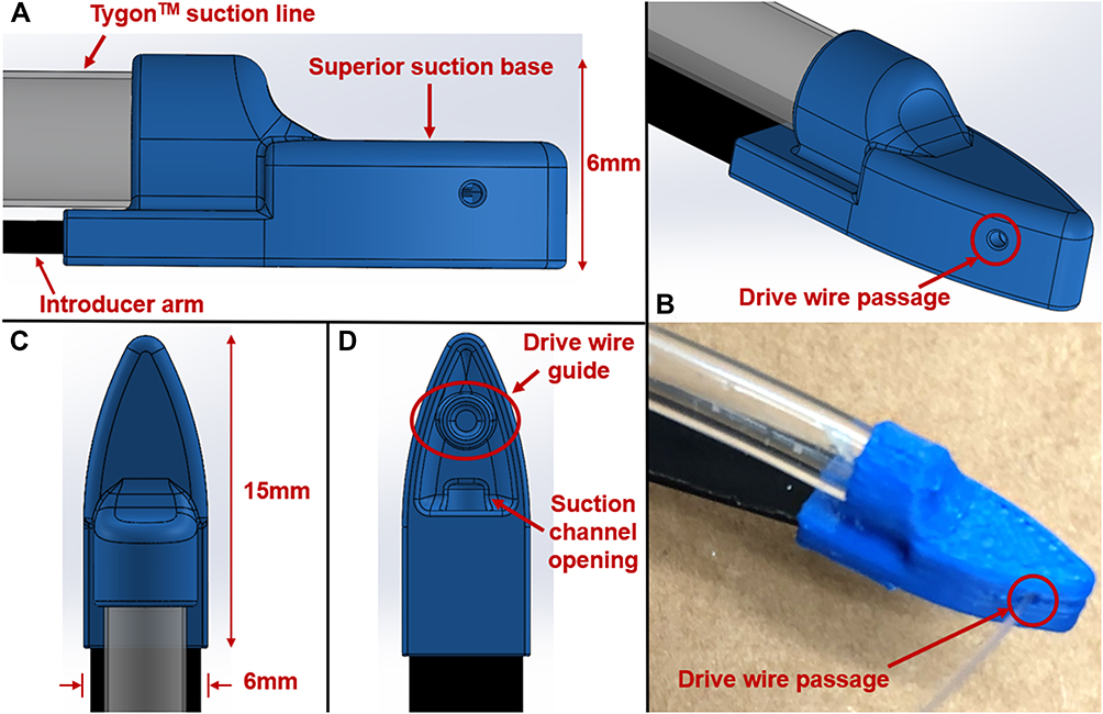 |
Figure 2 Design and prototype of the superior suction base. There are two superior suction bases, referred to as the anterior suction base and the posterior suction base. (A) Side view of the superior suction base, introducer arm, and TygonTM suction line. (B) Isometric view of the CAD model and prototyped model of the superior suction base, with the injector head drive wire passage highlighted. The model shown is the anterior suction base with the drive wire exiting from the suction base from the right. The posterior suction base will have a passage for the drive wire on the opposite side of that on the anterior suction base. (C) Top view of the superior suction base and TygonTM suction line. (D) Bottom view of the superior suction base and introducer arm. The injector head drive wire guide is highlighted, which directs the wire through the passage shown in (B), as well as the suction channel opening, which enables fixation of the suction base to its target region. |
Passage for the drive wire is shown in Figure 2B, where the anterior suction base is shown. The other superior suction base, referred to as the posterior suction base, will have a passage for the drive wire on the opposite side of that on the anterior suction base. The drive wire is then directed through the suction base by means of the drive wire guide (Figure 2D). The suction channel opening at the bottom of the superior suction base is also shown in Figure 2D, enabling fixation of the suction base to its target region. Positioning of the anterior and posterior suction bases at their respective target regions forms two of the three vertices required for HeartPrinter to achieve a stable platform on the heart.
Epicardial Guide
The epicardial guide is shown in Figure 3. Its objective is to direct the anterior suction base assembly, followed by the posterior suction base assembly, through a subxiphoid port via an accessory device, and through an incision in the pericardium. The suction base assembly refers to the respective superior suction base where the introducer arm and suction line are attached (Figure 2A). Once in the pericardial space, the epicardial guide is responsible for orienting and guiding the anterior and posterior suction bases along the exterior of the heart, so that they can reach their target destinations. This is achieved with its curved shape, which is designed to conform to the epicardial surface.
 |
Figure 3 Design and prototype of the epicardial guide. The shape of the epicardial guide is designed to conform to the exterior surface of the heart. (A) Isometric view. The top opening allows for insertion of the superior suction base with the suction line and introducer arm attached. The bottom opening allows for the superior suction base to exit and continue on towards the target region on the heart, either anteriorly or posteriorly. The cover on opposite sides prevents premature exit of the superior suction base with an opening less than the width of the superior suction base introducer arm. (B) Side view. The epicardial guide handle is shown, controllable by the operator. (C) Top view. (D) and (E) Side and isometric views of the prototyped epicardial guide and handle. |
The guide consists of a top opening, cover, and bottom opening (Figure 3A). The top opening enables insertion of the suction base assembly prior to insertion through a subxiphoid port via an accessory device. The cover on opposite sides prevents inadvertent and premature exit of the suction base assembly from the epicardial guide, ensuring that the suction base assembly is only released from the bottom opening. This is achieved by the opening between the covers on either side, which has a width less than the width of the superior suction base introducer arm. The bottom opening allows for withdrawal of the suction base assembly once in the pericardial space, directing it towards the exterior surface of the heart.
Inferior Suction Base
The inferior suction base is shown in Figure 4. The prototype was sourced from a previous prototype of HeartPrinter,9 and was deemed sufficient to present the introducer mechanisms in this paper. As shown, the two suction lines that are attached to the superior suction bases are directed through the inferior suction base. Since active suction on the inferior suction base was not required for the purposes of this study, the corresponding tubing was not attached.
 |
Figure 4 Prototype of the inferior suction base. The two suction lines from each superior suction base are directed through the inferior suction base. For the purposes of this study, suction is not required on the inferior suction base. |
Testing Model Setup
A rubber beating-heart model was used for testing the introducer mechanisms, which provided a detailed exterior as well as movement replicating a live human heart. The pulse rate was set to 72 beats per minute,20 and the heart was positioned anatomically with respect to the thorax (Model 1077, The Chamberlain Group, Great Barrington, MA) as seen in Figure 5A and B.21 The thorax contained a subxiphoid approach access port with a diameter of 40 mm (Figure 5B), which was used for testing. Although an accessory device of 20 mm was not used for testing the introducer mechanisms, the components were designed and tested with an accessory port to satisfy this criterion.
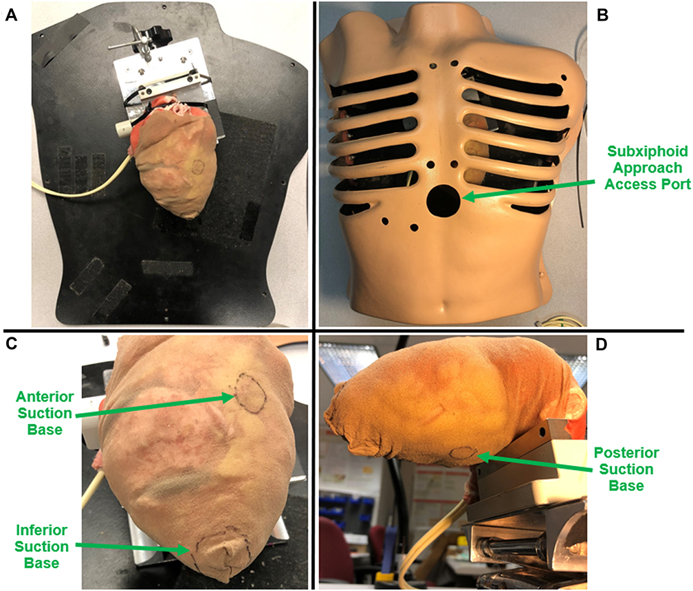 |
Figure 5 Testing model setup. (A) The rubber beating-heart was positioned anatomically and fixed in place. (B) Thorax with ribcage placed over the rubber heart. The subxiphoid approach access port was used for testing. (C and D) A nylon sock was placed snugly over the heart to replicate the pericardium. The target regions for the suction bases were labelled on the nylon sock with a marker. |
A nylon sock was fitted over the heart to replicate the pericardium (Figure 5A). As seen in Figure 5C and D, the target regions on the heart were indicated accordingly on the nylon sock with a marker. A flashlight was placed within the thorax to increase visibility for imaging. Two perpendicular cuts (2 cm, 1 cm) were made adjacent to each other on the pericardium near the apex of the heart to form a merged incision, as shown in Figure 6. Suction was provided to the superior suction bases through suction lines using a PowerVac Aspirator suction pump (Precision Medical, Northampton, PA).
 |
Figure 6 Two perpendicular cuts (2 cm, 1 cm) were made adjacent to each other on the pericardium near the apex of the heart to form a merged incision. |
The prototyped model of HeartPrinter used in this study is shown in Figure 7. The superior suction bases are shown with the suction lines and introducer arms attached, along with the inferior suction base. The suction lines pass through the inferior suction base and eventually out of the subxiphoid port, where they connect to the suction pump. The introducer arms can freely exit the body, allowing for direct manual control by the operator.
 |
Figure 7 Prototype of HeartPrinter used for testing. The superior suction bases, introducer arms, suction lines, and inferior suction base are shown. The injector head which completes the HeartPrinter system is not shown. |
Introducer Mechanism I
The workflow for the first introducer mechanism is shown in Figure 8, with positioning of the anterior suction base, posterior suction base, and inferior suction base displayed in sequential order.
 |
Figure 8 Introducer Mechanism I. The workflows in sequential order are depicted for positioning the: (A) anterior suction base; (B) posterior suction base; (C) inferior suction base. |
Workflow – Anterior Suction Base
The surgical workflow for positioning the anterior suction base is shown in Figure 8A. First, the anterior suction base assembly, with the suction line and introducer arm, is inserted into the epicardial guide (i). This is achieved by manipulating the epicardial guide handle and the introducer arm. Then, the epicardial guide, with the suction base assembly held within, is inserted through the subxiphoid port (ii), and then through the incision on the pericardium (iii). Once access is achieved through the pericardium to the anterior side of the heart, the anterior suction base assembly exits from the bottom opening of the epicardial guide, and moves along the exterior surface of the heart towards the target region (iv). Upon reaching the target region, suction is activated to fix the anterior suction base to the heart. This then enables the introducer arm to be removed from the anterior suction base and the body (v). Finally, the epicardial guide is removed from underneath the suction line and exits the body (vi).
Workflow – Posterior Suction Base
The process for positioning the posterior suction base is shown in Figure 8B. As was done in the anterior suction base workflow, the posterior suction base assembly is inserted into the epicardial guide (i). The same epicardial guide is used as previously. With the epicardial guide now flipped and the posterior suction base assembly inside, it is inserted through the subxiphoid port (ii), and then through the incision on the pericardium (iii). Similarly, once access is achieved to the posterior side of the heart, the posterior suction base assembly exits, and moves towards its target region (iv). After suction is activated, the introducer arm (v) and epicardial guide (vi) are removed from the body as described previously.
Workflow – Inferior Suction Base
The procedure for positioning the inferior suction base is shown in Figure 8C. This process makes use of a tool (i) that is able to grasp the suction lines and push the inferior suction base forward. At the contact interface with the suction lines, this tool utilizes a set of extrusions that run parallel to the suction lines, facilitating its smooth translation along the suction lines while it is operated by the operator. For prototyping purposes, a set of tweezers is used and two complimentary 3D printed parts are fit onto the tweezer tip.
The workflow consists of the following. First, the tool grabs hold of the suction lines immediately proximal to the inferior suction base (ii). The operator then pushes the tool forward along the suction lines, thereby pushing the inferior suction base through the subxiphoid port (iii). This continues until the inferior suction base passes through the incision on the pericardium, which is followed by placing the suction base near the apex of the heart (iv). After placing the suction base at its target region and suction is activated, the tool is retracted from the body by the operator (v). The inferior suction base is then fixed to the apex of the heart (vi), forming the triangular support structure for the injector head to operate in.
Introducer Mechanism II
Design
The second introducer mechanism is shown in Figure 9. This is an additional concept that provides an alternative method for positioning the inferior suction base. This mechanism makes use of two additional cable lines, shown in green, that are fixed to the introducer arms, depicted by the yellow markers. The cable lines then pass through the drive wire passages on the superior suction bases to the inferior suction base. At the proximal end, the cable lines are directed through the inferior suction base to a pushing tool, shown in red, and are fixed with respect to the pushing tool. This pushing tool is located proximal to the inferior suction base, and is held in immediate contact with it. The suction lines are also fixed in place at the proximal end adjacent to the pushing tool. The objective of the pushing tool is to propel the inferior suction base towards the apex of the heart by pulling the cable lines connected to the introducer arms.
 |
Figure 9 Introducer Mechanism II. This mechanism functions through the pushing tool, indicated in red, that directs the inferior suction base towards the apex of the heart. Cable lines, shown in green, which travel from the pushing tool to the introducer arms, passing through the drive wire passages on the superior suction bases, are pulled in order to propel the pushing tool forwards. |
Workflow – Superior Suction Bases
The workflow for positioning of the superior suction bases is identical to that of the first introducer mechanism, with the exception of one factor for increased usability. As the cable lines are fixed to the introducer arms (Figure 9), the introducer arms should ideally not be fully removed from the surgical site prior to the epicardial guide. If this occurs, the epicardial guide may be pulled along when the introducer arms are removed, as the cover of the epicardial guide (Figure 3A) may enclose the cable lines (Figure 9), which is not desired. Therefore, for this mechanism, the epicardial guide can be removed from the surgical site prior to the introducer arm. Since the opening on the epicardial guide restricts passage of the introducer arm using covers on opposite sides (Figure 3A), the process of removing the epicardial guide entails the following. First, the epicardial guide is retracted along the suction line by the operator through the incision in the pericardium and the subxiphoid port. Then, while holding the epicardial guide stable, the introducer arm is rotated 90° within the epicardial guide to allow its thinner wall to align with the bottom opening of the epicardial guide (Figure 3A), and the epicardial guide can be removed. The thinner wall of the introducer arm is shown in Figure 2A.
Workflow – Inferior Suction Base
Figure 10 illustrates the setup of the introducer mechanism after removal of the epicardial guide. In order to improve visualization, the thorax is not shown. Figure 10A is a snapshot prior to the introducer arms being retracted from the surgical site, with suction activated at the superior suction bases. The cable lines, pushing tool, and fixation of the suction lines proximally are shown. Figure 10B demonstrates pulling of the introducer arms, which drives the pushing tool towards the apex of the heart via the cable lines. The fixation points of the cable lines on the introducer arms are shown.
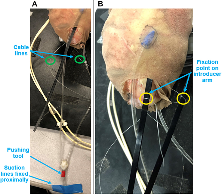 |
Figure 10 Setup of Introducer Mechanism II after removal of the epicardial guide and suction is activated at the superior suction bases. In order to improve visualization, the thorax is removed for this figure. (A) The introducer arms are still slotted into the superior suction bases, with a cable line fixed to each introducer arm, circled in green. The pushing tool located proximally to the inferior suction base is shown in red. The suction lines are fixed at the proximal end, which enables the pushing tool to direct the inferior suction base along the suction lines and towards the target region. (B) The introducer arms are pulled from their slots on the superior suction bases. The fixation points for the cable lines on the introducer arms are now visible, circled in yellow. These will continue to be retracted, thereby directing the pushing tool forwards. |
The process of positioning the inferior suction base once the introducer arms have been pulled from the two superior target regions and out of the incision and port is shown in Figure 11. As the cable lines are pulled away from the surgical site, this drives the pushing tool towards the target region, directing the inferior suction base (Figure 11A) until the apex of the heart is reached (Figure 11B). Once the inferior suction base is fixed to the apex of the heart, the triangular support structure is formed for the injector head to operate in.
 |
Figure 11 Process of positioning the inferior suction base near the apex of the heart. (A) The anterior and posterior cable lines are pulled in order to direct the pushing tool forwards, thereby propelling the inferior suction base towards its target region. (B) The cable lines continue to be pulled until the inferior suction base reaches the apex of the heart. |
Procedure Duration Testing
Time measurements for insertion of the epicardial guide into the pericardial space, which includes inserting the superior suction base assembly into the epicardial guide, and positioning of the superior suction bases and the inferior suction base using both introducer mechanisms were collected. Five trials (n = 5) were performed for each introducer mechanism, following the outlined workflows described previously.
Epicardial Guide Insertion Force Testing
Force measurements for insertion of the epicardial guide through the pericardium using a subxiphoid approach were collected. A force gauge (Nextech Global Company Limited, Thailand) with a 3D printed coupler was used with the epicardial guide for measurements (Figure 12). Ten trials (n = 10) were performed each for insertion of the guide providing anterior access (Figure 12A) and posterior access (Figure 12B) to the pericardial space. Peak forces of the epicardial guide inserting through the incision on the pericardium were extracted.
 |
Figure 12 Set-up for epicardial guide insertion force measurements. A 3D printed coupler is used to connect the epicardial guide to the force gauge. (A) Insertion for anterior access to the heart. (B) Insertion for posterior access to the heart. |
Results
Testing on the Heart Model – Introducer Mechanism I
All suction bases for the prototype of HeartPrinter demonstrated successful positioning at their respective target regions on the heart using Introducer Mechanism I. Each suction base was positioned sequentially after being inserted through the subxiphoid approach access port and the incision on the pericardium, and adherence to the surface of the epicardium was achieved for the superior suction bases, which were connected to the suction pump. Positioning of the suction bases is shown in Figure 13, outlined by the target regions labelled with a marker on the pericardium and an overlaid identifier on the images in green.
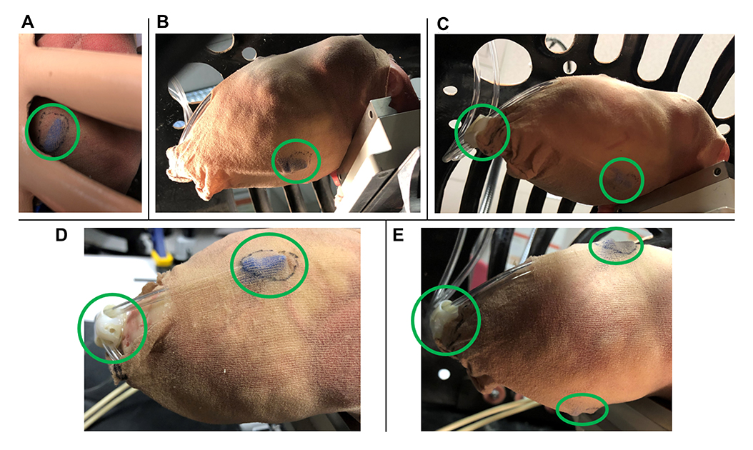 |
Figure 13 Captured images of successful positioning of the suction bases on the heart using Introducer Mechanism I. (A) Anterior suction base. (B) Posterior suction base. (C) Inferior suction base and posterior suction base. (D) Inferior suction base and anterior suction base. The thorax was removed for improved visualization. (E) All three suction bases positioned at their target regions, forming the triangular support structure. |
Testing on the Heart Model – Introducer Mechanism II
All suction bases were positioned successfully at their respective target regions on the heart using Introducer Mechanism II. Each suction base was positioned sequentially after being inserted through the subxiphoid approach access port and the incision on the pericardium, and adherence to the surface of the epicardium was achieved for the superior suction bases. Since positioning of the superior suction bases is equivalent to that of Introducer Mechanism I (Figure 13), only positioning of the inferior suction base is shown in Figure 14. Successful positioning is outlined with an overlaid identifier in green.
 |
Figure 14 Captured image of successful positioning of the inferior suction base near the apex of the heart, using Introducer Mechanism II. |
Procedure Duration Testing
Time duration measurements for insertion of the epicardial guide and positioning of the suction bases are shown in Table 1 using Introducer Mechanism I, and Table 2 using Introducer Mechanism II. The total mean procedure time was 230 ± 7 seconds for Introducer Mechanism I, and 259 ± 4 seconds for Introducer Mechanism II. The time required to position the inferior suction base was approximately 20 seconds longer for mechanism II compared to mechanism I. Additionally, positioning of the anterior suction base required approximately 5 seconds more than the posterior suction base for both introducer mechanisms. On the other hand, insertion anteriorly of the epicardial guide through the pericardium required approximately 8 seconds fewer in comparison to insertion posteriorly for both introducer mechanisms.
 |
Table 1 Epicardial Guide Insertion and Suction Base Positioning Time Measurements Using Introducer Mechanism I |
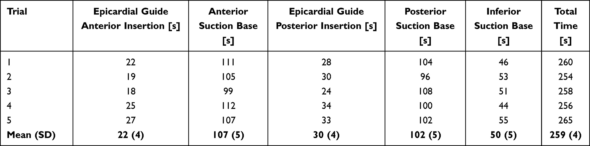 |
Table 2 Epicardial Guide Insertion and Suction Base Positioning Time Measurements Using Introducer Mechanism II |
Epicardial Guide Insertion Force Testing
Sample plots for a specific trial of continuous forces experienced by the epicardial guide over time during anterior and posterior access are shown in Figure 15. The mean peak insertion force for anterior access was 2.2 ± 0.4 N; for posterior access it was 3.1 ± 0.4 N.
 |
Figure 15 Sample plots of specific trials showing continuous force measurements experienced by the epicardial guide for (A) anterior access and (B) posterior access. Negative values correspond to compression forces which are of interest. |
Discussion
The presented introducer mechanisms meet the outlined design requirements described previously. The size and shape of the components used in these mechanisms allow for insertion through a subxiphoid approach via an accessory device and incision on the pericardium. It was demonstrated that the suction bases can be accurately directed towards the target regions on the heart, enabling correct positioning in order to define the workspace for HeartPrinter. Positioning of the suction bases at their target regions was done both efficiently and consistently, as demonstrated by the measurements of positioning time and peak insertion force.
The superior suction bases were successful in reaching their target regions on the anterior and posterior sides of the heart using both introducer mechanisms, as can be seen in Figure 13 for the first introducer mechanism. Adherence to the surface of the heart using suction for the superior suction bases, although successful in maintaining its position during the procedure, was observed to fluctuate on the suction pump reading by approximately 20 cmHg. This may have been affected by the worn surface of the rubber heart model. Future work on the superior suction bases will aim to strengthen the vacuum seal formed with the surface of the heart to ensure sufficient adherence throughout the operation, as well as increase geometrical matching of the suction lines fitted into the circular fittings on the superior suction bases. Improved adherence to the heart will increase the effectiveness of positioning of the inferior suction base for both presented introducer mechanisms.
The mean duration for positioning the anterior suction base required approximately 5 seconds more than the posterior suction base using both introducer mechanisms (Tables 1 and 2). Although this is not a large difference, a possible explanation for this is the greater degree of surface fluctuations on the anterior side of the heart model, which required greater manipulation of the introducer arm to direct the anterior suction base over these fluctuations and to its target region.
The introducer arms provided sufficient maneuverability for the two superior suction bases in being able to exit the epicardial guide, and slide along the surface of the heart. However, as seen in Figure 13D for the anterior suction base on the pericardium, there is a noticeable transition in the profile between the proximal and distal ends of the suction base. Increasing the smoothness of this transition will further improve maneuverability of the superior suction bases along the epicardium in order to reach their target destinations, as the restriction from the pericardium due to this sharp transition would be reduced. Further development on the introducer arms will continue, focusing on usability, material selection, navigation along the epicardium, and fit within the slot of the superior suction base.
The epicardial guide and handle demonstrated the ability to direct the superior suction bases through a subxiphoid approach and an incision on the pericardium, as well as oriented and guided the superior suction bases anteriorly and posteriorly around the heart in order to reach their target regions (Figure 13). Peak insertion forces through the pericardium were consistent and relatively low for both anterior and posterior access. The greater force required for posterior access is likely due to the need to curve more around the heart posteriorly compared to anteriorly. This required greater manipulation of the epicardial guide handle in order to align the bottom opening of the epicardial guide with the posterior side of the heart, and therefore greater force.
Due to greater manipulation of the epicardial guide handle, more time was required to insert the epicardial guide posteriorly compared to anteriorly, shown in Tables 1 and 2. However, once the bottom opening of the epicardial guide was aligned with the posterior side of the heart, positioning of the posterior suction base was straightforward and quick due to fewer surface deviations on the surface of the rubber heart model, as explained previously.
As the concept for the use of the epicardial guide was proven on the rubber beating-heart model, the design and use of the epicardial guide will continue to be improved upon. This includes verification of and possible modifications to the curved shape in order to conform to the exterior surface of the heart, and assessment and comparison of insertion forces on an enhanced testing model.
Positioning of the inferior suction base using the designed tool of Introducer Mechanism I (Figure 8C) provided both an efficient and highly effective method for sliding the suction base along the suction lines and towards the apex of the heart (Figure 13). This also enabled a high level of control by the operator over the speed at which the inferior suction base was directed towards its target region. Therefore, as shown in Tables 1 and 2, positioning of the inferior suction base using the first mechanism was approximately 20 seconds quicker compared to the second mechanism. This was also expected as for the second introducer mechanism, the cable lines had to be pulled slowly in order to prevent the superior suction bases from dislodging and losing their adherence to the heart. One limitation that Introducer Mechanism I presents is that it requires direct contact with the inferior suction base throughout the positioning process, which could be affected near the end of the positioning process with decreased visibility and access for the operator.
Positioning of the inferior suction base using Introducer Mechanism II demonstrated another method for directing the suction base towards the apex of the heart (Figure 14). The value of the cable lines was also illustrated, as they make use of the introducer arms and drive wire passage on the superior suction bases, therefore removing the need for an additional tool to be manipulated by the operator directly on the inferior suction base. This could be particularly useful towards the end of the positioning process for the inferior suction base, as visibility and access for the operator become increasingly limited. However, as mentioned previously, the cable lines had to be pulled slowly to prevent dislodging of the superior suction bases from the heart, and would therefore benefit from greater adhesion between the superior suction bases and the surface of the heart. Another modification that will be considered is having the cable lines feed directly along the suction lines towards the inferior suction base instead of hanging freely, in order to increase organization of items within the workspace.
Although in this study adherence to the epicardium for the suction bases was assessed on an artificial beating heart, previous studies with HeartPrinter9 and HeartLander,20,22 a tethered epicardial crawling robot, have demonstrated robustness to varying conditions in vivo on porcine models and ex vivo on fresh ovine hearts. In particular, aspiration of liquid through the suction lines has been minimal, and the suction plates have performed adequately in these environments.9,20 Moreover, Patronik et al have examined the effects of epicardial fat on the suction chambers of HeartLander.22 It was demonstrated that while some epicardial fat did accumulate in the suction chamber, it will not clog the suction line, and the ability of the suction chamber to generate traction did not decrease.22 Traction was affected on exposed epicardial fat,22 however it is not expected that HeartPrinter will often encounter adipose tissue with this level of exposure.
This study is a preliminary proof of feasibility. The primary limitation of this study is of course the artificiality of the model of the heart and cardiothoracic environment. Future steps will focus on assessment with improved representation of the surgical environment, and quantitative evaluation of the introducer mechanisms against those presented here. Moreover, in the long term, the size of both the manipulator and its introducer will be reduced greatly, as the plan for clinical use involves a diameter much smaller than 20 mm, but for these initial proofs of feasibility the focus was on enabling deployment through the size of cannula that has been used to date. The plan for reducing the size will focus on minimizing the cross-sections of the suction line and introducer arm, which will enable greater miniaturization of the suction bases and the epicardial guide. In particular, greater emphasis will be placed on minimizing the height of each component, which is typically in the direction normal to the surface of the heart.
Conclusion
This study demonstrates the preliminary proof of feasibility of two novel introducer design concepts in facilitating HeartPrinter’s deployment on the epicardium of an artificial beating heart. Evaluation of pericardium insertion forces and procedure times were both consistent and reasonable. Future work will be directed towards improving the representation of the heart and cardiothoracic environment for testing, evaluating and refining the introducer design concepts using the revised testing environment, and scaling the size of the introducer design concepts down for clinical use compatibility, in order to ensure HeartPrinter is positioned on the heart both effectively and efficiently.
Funding
This research was partially supported by the US National Institutes of Health (grant nos. R01EB078839 and R01HL105911).
Disclosure
Professor Cameron N Riviere reports holding equity in HeartLander Surgical, Inc; In addition, Professor Cameron N Riviere has a patent US10736703B2 issued to Carnegie Mellon University. The authors report no other conflicts of interest in this work.
References
1. Cannatà A, Ali H, Sinagra G, Giacca M. Gene therapy for the heart: lessons learned and future perspectives. Circ Res. 2020;126(10):1394–1414. doi:10.1161/CIRCRESAHA.120.315855
2. Ishikawa K, Tilemann L, Fish K, Hajjar RJ. Gene delivery methods in cardiac gene therapy. J Gene Med. 2011;13(10):566–572. doi:10.1002/jgm.1609
3. Katz MG, Fargnoli AS, Pritchette LA, Bridges CR. Gene delivery technologies for cardiac applications. Gene Ther. 2012;19(6):659–669. doi:10.1038/gt.2012.11
4. Kiyotake I, Thomas W, Hajjar Roger J. Human cardiac gene therapy. Circ Res. 2018;123(5):601–613. doi:10.1161/CIRCRESAHA.118.311587
5. Fromes Y, Salmon A, Wang X, et al. Gene delivery to the myocardium by intrapericardial injection. Gene Ther. 1999;6(4):683–688. doi:10.1038/sj.gt.3300853
6. Trivedi A, Hoffman J, Arora R. Gene therapy for atrial fibrillation - how close to clinical implementation? Int J Cardiol. 2019;296:177–183. doi:10.1016/j.ijcard.2019.07.057
7. Donahue JK. Cardiac gene therapy: a call for basic methods development. Lancet. 2016;387(10024):1137–1139. doi:10.1016/S0140-6736(16)00149-5
8. Cleveland JC, Shroyer AL, Chen AY, Peterson E, Grover FL. Off-pump coronary artery bypass grafting decreases risk-adjusted mortality and morbidity. Ann Thorac Surg. 2001;72(4):1282–1288. doi:10.1016/S0003-4975(01)03006-5
9. Costanza AD, Wood NA, Passineau MJ, et al. A parallel wire robot for epicardial interventions. In:
10. Mack MJ. Minimally invasive and robotic surgery. JAMA. 2001;285(5):568. doi:10.1001/jama.285.5.568
11. Beasley RA. Medical robots: current systems and research directions. J Robotics. 2012;2012:e401613. doi:10.1155/2012/401613
12. Breault MS, Costanza AD, Wood NA, Passineau MJ, Riviere CN. Toward hybrid force/position control for the Cerberus epicardial robot. Annu Int Conf IEEE Eng Med Biol Soc. 2015;2015:7776–7779. doi:10.1109/EMBC.2015.7320195
13. Liu C, Moreira P, Zemiti N, Poignet P. 3D force control for robotic-assisted beating heart surgery based on viscoelastic tissue model. Annu Int Conf IEEE Eng Med Biol Soc. 2011;2011:7054–7058. doi:10.1109/IEMBS.2011.6091783
14. Peters BS, Armijo PR, Krause C, Choudhury SA, Oleynikov D. Review of emerging surgical robotic technology. Surg Endosc. 2018;32(4):1636–1655. doi:10.1007/s00464-018-6079-2
15. Cheng L, Sharifi M, Tavakoli M. Towards robot-assisted anchor deployment in beating-heart mitral valve surgery. Int J Med Robot. 2018;14(3):e1900. doi:10.1002/rcs.1900
16. Liang F, Yu Y, Wang H, Meng X. Heart motion prediction in robotic-assisted beating heart surgery: a nonlinear fast adaptive approach. Int J Adv Robotic Sys. 2013;2:548. doi:10.5772/55581
17. Kampa G, Barlow A, Morgan KL, et al. Intrapericardial delivery tools and methods. U. S. Patent No. 8,012,143; 2011.
18. Katz MG, Swain JD, Tomasulo CE, Sumaroka M, Fargnoli A, Bridges CR. Current strategies for myocardial gene delivery. J Mol Cell Cardiol. 2011;50(5):766–776. doi:10.1016/j.yjmcc.2010.09.003
19. Shi H, Xue T, Yang Y, et al. Microneedle-mediated gene delivery for the treatment of ischemic myocardial disease. Science Advances. 2020;6(25):eaaz3621. doi:10.1126/sciadv.aaz3621
20. Ota T, Patronik NA, Riviere CN, Zenati MA. Percutaneous subxiphoid access to the epicardium using a miniature crawling robotic device. Innovations. 2006;1(5):227–231. doi:10.1097/01.IMI.0000240673.14388.fc
21. Moores DWO, Allen KB, Faber LP, et al. Subxiphoid pericardial drainage for pericardial tamponade. J Thorac Cardiovasc Surg. 1995;109(3):546–552. doi:10.1016/S0022-5223(95)70287-3
22. Patronik NA, Zenati MA, Riviere CN. A study ex vivo of the effect of epicardial fat on the HeartLander robotic crawler. IFMBE Proc. 2012;37(Part1, Part 3):227–230. doi:10.1007/978-3-642-23508-5_60
 © 2021 The Author(s). This work is published and licensed by Dove Medical Press Limited. The
full terms of this license are available at https://www.dovepress.com/terms
and incorporate the Creative Commons Attribution
- Non Commercial (unported, 3.0) License.
By accessing the work you hereby accept the Terms. Non-commercial uses of the work are permitted
without any further permission from Dove Medical Press Limited, provided the work is properly
attributed. For permission for commercial use of this work, please see paragraphs 4.2 and 5 of our Terms.
© 2021 The Author(s). This work is published and licensed by Dove Medical Press Limited. The
full terms of this license are available at https://www.dovepress.com/terms
and incorporate the Creative Commons Attribution
- Non Commercial (unported, 3.0) License.
By accessing the work you hereby accept the Terms. Non-commercial uses of the work are permitted
without any further permission from Dove Medical Press Limited, provided the work is properly
attributed. For permission for commercial use of this work, please see paragraphs 4.2 and 5 of our Terms.