Back to Journals » Clinical, Cosmetic and Investigational Dentistry » Volume 12
Distal Extension Denture – Case Report and Overview
Authors Yeung C ![]() , Leung KCM
, Leung KCM ![]() , Yu OY
, Yu OY ![]() , Lam WYH
, Lam WYH ![]() , Wong AWY
, Wong AWY ![]() , Chu CH
, Chu CH ![]()
Received 13 August 2020
Accepted for publication 8 October 2020
Published 10 November 2020 Volume 2020:12 Pages 493—503
DOI https://doi.org/10.2147/CCIDE.S276717
Checked for plagiarism Yes
Review by Single anonymous peer review
Peer reviewer comments 3
Editor who approved publication: Professor Christopher E. Okunseri
Conson Yeung, Katherine Chiu Man Leung, Ollie Yiru Yu, Walter Yu Hang Lam, Amy Wai Yee Wong, Chun Hung Chu
Faculty of Dentistry, The University of Hong Kong, Hong Kong
Correspondence: Chun Hung Chu
Prince Philip Dental Hospital, 3B26, 34 Hospital Road, Sai Ying Pun, Hong Kong
Tel +852 2859 0287
Email [email protected]
Abstract: Replacing missing teeth distal to the last standing teeth with removable partial dentures poses considerable challenge to dentists. However, the insertion of implants turns a free-end saddle into a bounded saddle. Still, patients may not be able to accept implant insertions due to financial reasons, systemic medical conditions, local anatomical factors or complicated treatments involving surgery. Hence, patients with missing teeth often prefer to use removable partial dentures to improve their dental aesthetics and to restore their oral function. In this article, we use a clinical case to illustrate the clinical procedures required for the fabrication of a distal extension denture with good retention, support, stability, aesthetics and masticatory function. We also review the design for a clasp assembly on the abutment adjacent to the distal edentulous ridge.
Keywords: distal extension denture, altered cast technique
Corrigendum for this paper has been published
Introduction
The construction of distal extension dentures poses great challenges to dentists because no abutment tooth is distal to the edentulous area to provide retention, support or stability. The saddle area can rotate both away from and towards the mucosa. However, the insertion of implants turns a free-end saddle into a bounded saddle. Still, implants may not be suitable due to financial reasons; systemic conditions, such as immunodeficiency; or local anatomical factors, such as an insufficient bone quantity or a poor quality of bone, which requires grafting procedures. Finally, some patients may prefer a simpler treatment that does not require surgery. Hence, a removable partial denture is often the preferred treatment option.
The free-end saddle of a partial denture can rotate gingivally under functional loading. This rotational movement is harmful to the periodontium of the abutment tooth adjacent to the saddle. Kratochvil1 proposed a design consisting of a mesial occlusal rest, a proximal plate, and an I-bar to minimise this potential damage.
Krol2 described a clasp design, the RPI clasp, with an I-bar and a proximal plate to minimize tooth surface coverage and a mesial rest to reduce stress on the abutment tooth. Eliason3 further proposed using an Akers’ clasp, the RPA clasp, when I-bars are contraindicated. A number of other designs have also been proposed.4–6 This article is a case report aimed at discussing the fabrication of a removable partial denture that provides distal extension with good retention, support, stability, aesthetics and masticatory function. In particular, denture designs and the altered cast technique needed to address problems related to free-end saddles are discussed.
Case Report
History and Findings/Diagnosis
A 65-year-old man presented with complaints of difficulty in chewing, recurrent pain from various regions of the mouth, and poor dental aesthetics. The medical history was clear. No abnormality was detected upon extra-oral examination.
A thorough intra-oral examination and radiographic examination yielded the following findings: only the anterior teeth were in occlusion, and the occlusal vertical dimension was reduced (Figure 1). The mandibular anterior teeth showed signs of severe incisal and labial wear (Figure 2). Multiple carious teeth, retained roots, over-contoured and splinted metal-ceramic crowns, and multiple missing teeth were found on the maxillary arch (Figure 3). Meanwhile, multiple missing teeth and teeth with severe wear were found on the mandibular arch (Figure 4). A radiographic examination confirmed multiple caries on the teeth of both arches, as well as periodontal disease with generalized moderate-to-severe horizontal bone loss (Figure 5). Apical radiolucencies were observed on the retained roots of the maxillary arch and on the anterior teeth of the mandibular arch.
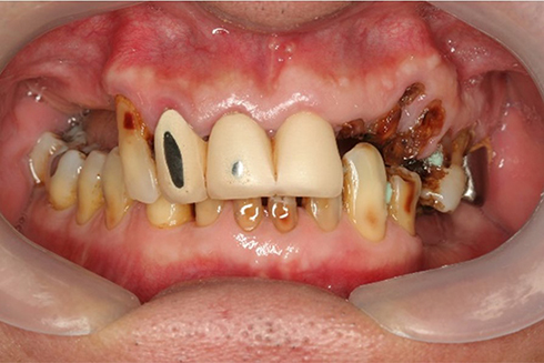 |
Figure 1 Frontal view, habitual occlusion. |
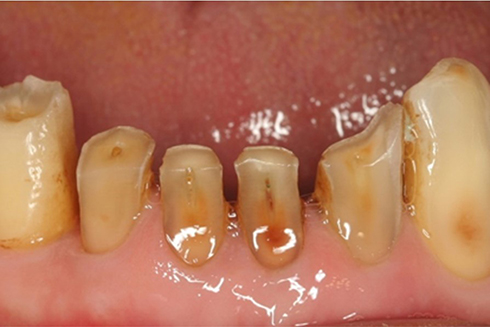 |
Figure 2 Severe wear of lower anterior teeth. |
 |
Figure 3 Upper occlusal view (flipped mirror image). |
 |
Figure 4 Lower occlusal view (flipped mirror image). |
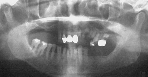 |
Figure 5 Pretreatment orthopantomogram. |
The findings were explained to the patient, and a treatment plan was formulated after a thorough discussion. Scaling was provided, and oral hygiene instructions were given. The carious lesion on the right mandibular first molar was stabilized, and the carious lesion on the right mandibular second premolar was restored with disto-occlusal amalgam. Due to the poor prognosis of the maxillary teeth, maxillary clearance was then performed, and an immediate complete maxillary denture was provided. The right mandibular first molar required root canal treatment and was referred to a specialist for management. However, an appointment could be made only 11 months later. It was decided to first construct an immediate maxillary complete denture to improve the patient’s dental aesthetics and to address the patient’s chewing problems as he awaited specialist endodontic care. The provision of a maxillary complete denture could improve the aesthetics/mastication and prevent excessive wear of the remaining teeth even without a mandibular removable partial denture.
Treatment of the Mandibular Arch
Shortly after delivery of the immediate maxillary complete denture, the mandibular incisors were extracted due to severity of the bone loss around these teeth and the presence of apical pathologies. These teeth were kept until the maxillary complete denture was delivered; otherwise, only the right canines would have been in occlusion.
The right mandibular first molar was endodontically treated. A mandibular removable partial denture was planned. Maxillary and mandibular study impressions were taken after wound healing was observed a few months following the extractions of the mandibular incisors. The lower cast was surveyed, and a partial denture was designed. In view of the amount of non-carious tooth substance loss on the occlusal and buccal aspects of the left mandibular first premolar, a metal-ceramic crown was planned for the tooth. A metal-ceramic crown was also planned for the endodontically treated right mandibular first molar. The ideal locations and contours for the rest seats, reciprocal planes and undercut areas were incorporated into the crowns (Figure 6).
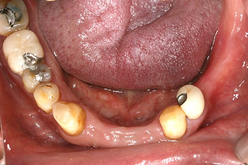 |
Figure 6 Surveyed crowns (flipped mirror image). |
After the crowns were cemented and the necessary mouth preparation was performed, a lower working impression was taken. Next, the cobalt-chromium framework was fabricated for denture framework try-in. The fit of the framework was considered to be satisfactory (Figure 7). The framework was returned to the laboratory for the addition of a close-fitting self-cured acrylic resin tray to the free-end saddle area. The tray area was added after try-in because an accurate observation of the fit of the framework could be made without the tray. In addition, if the framework failed to seat properly, the operator would not have to wonder whether the interference came from the framework or the tray.
 |
Figure 7 Metal framework in situ (flipped mirror image). |
The tray should have a full extension similar to that of a complete denture in the corresponding region (Figure 8). This means that the tray should cover the retromolar pad distally and the external oblique ridge buccally. The flange of the tray should extend lingually to the full functional depth of the lingual sulcus (see below). After the framework was tried with the tray attached to it in the mouth, the tray was cleaned and dried. Zinc oxide eugenol impression paste (Kelly’s paste, Waterpik Inc., Collins, CO, USA) was applied, and the framework was seated in the mouth. Meanwhile, the patient was instructed to protrude his tongue to record the lingual sulcus with the mylohyoid muscle contracted. This could prevent the denture from displacement due to the movement of the muscle during its function (Figure 9). The minimal space between the fitting surface of the tray and the mucosa, together with the viscosity of the zinc oxide eugenol, means that pressure was exerted to the mucosa to displace it. This will help to increase the load that the mucosa shares, and it will minimize the downward movement of the saddle (see later discussion). It is important that the tray does not show through the impression material (Figure 10). Next, the saddle area was removed from the master cast. The framework was seated and sealed in position. Dental stone (Type III gypsum) was poured to form the saddle area in the altered master cast.
 |
Figure 8 Proper extension of the tray. |
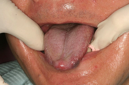 |
Figure 9 Tongue protruded during impression taking. |
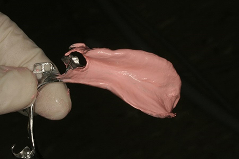 |
Figure 10 No tray shows through the impression. |
Because the remaining opposing teeth did not indicate a well-defined intercuspal position, a wax rim was constructed. An interocclusal record and a facebow record were taken so that the maxillary cast could be properly mounted. Meanwhile, the mandibular cast could be mounted in the determined intercuspal position. Also, the size, mould and shade of the denture teeth to be used were determined.
Next, wax try-in was performed. The patient was satisfied with the appearance. The denture was then processed and finished. At the delivery appointment, the jaw position and occlusion were verified. Detailed denture maintenance instructions were provided. The patient was very satisfied with the result (Figures 11 and 12). The patient then attended a yearly review for 10 years till the present. During the follow-up period, denture clasps were adjusted to improve retention. No other denture adjustment, such as relining, was necessary. At 10 years after denture delivery, no significant resorption of residual ridge corresponding to the free-end saddle area was observed (Figure 13). However, signs of the attrition of the artificial teeth were noticed (Figure 14).
 |
Figure 11 Lower denture in situ (flipped mirror image). |
 |
Figure 12 Frontal view with dentures. |
 |
Figure 13 Ten-year post-treatment orthopantomogram. |
 |
Figure 14 The denture 10 years after delivery (flipped mirror image). |
Discussion
Combination syndrome can happen when the anterior mandibular teeth oppose a maxillary complete denture. The risk is increased when the posterior teeth are missing. According to some clinicians, this clinical condition can increase the resorption rate of the maxillary anterior ridge and hence result in comparatively large tuberosities.7 This patient had some posterior mandibular teeth, although he had lost his mandibular incisors. He was not in the high-risk category for the development of this syndrome. No signs of combination syndrome were observed in the regular reviews over the 10-year period.
A tissue stop was not used in this case. A tissue stop can be incorporated into the distal end of the framework in the area of the distal extension to provide stability to the framework during the stages of transfer and processing. It also prevents the distortion of the framework during the processing of acrylic resin.8 The slightly short distal extension of the framework may cause flexing of the acrylic baseplate upon occlusal loading. In addition, the few openings in the meshwork may cause problems with retention of the acrylic baseplate to the framework. The occlusal load at the distal extension is considered to be low, as it is opposed to a complete denture. Furthermore, border molding can be performed to produce an adequately extended distolingual flange of the denture. This will help to enhance the stability and support of dentures.
We placed an occlusal rest seat on the disto-occlusal amalgam restoration of the right mandibular second premolar. It was not considered to be a problem because a sufficient thickness of amalgam was present beneath the occlusal rest seat (Figure 13). In addition, the occlusal load transmitted to the mandibular removable partial denture may not be high, as it was opposed to a complete denture. The patient could not afford an abutment crown on the right mandibular second premolar due to financial constraints. Thus, we prepared an occlusal rest seat on the restoration, which had a sufficient thickness of amalgam.
Although implants are favourable options for replacing missing teeth, clinicians should have good knowledge and skills in making removable partial dentures. This case report discusses the challenges of fabricating a removable partial denture with missing posterior teeth. An abutment tooth distal to the free-end saddle area is lacking in distal extension dentures. Thus, means of minimizing the rotation of the saddle both towards and away from the mucosa need to be sought.
Rotation Away from the Mucosa
All the mandibular incisors were missing. In this situation, it may appear that sufficient indirect retention cannot be achieved. This is because the distance from the mesial occlusal rest on the left mandibular first premolar to the rests on the canines measured in a direction parallel to the sagittal plane is short. As a result, the rests on the canines will not be effective for providing indirect retention. However, it is incorrect to assume that a line perpendicular to the sagittal plane that passes through the mesial occlusal rest on the left mandibular first premolar will form the fulcrum axis. The direct retainers resist the movement of the denture away from the mucosa when the saddle area is subject to a force directed away from the mucosa. It is therefore the line joining the tips of the most posterior direct retainers on each side that will form the fulcrum line (line AB in Figure 15). The rest’s position on the right mandibular canine provided indirect retention. Such retention would not be inferior to a situation in which the mandibular incisors are present.
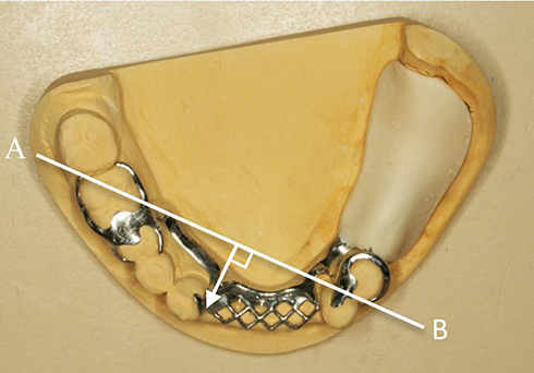 |
Figure 15 Indirect retention in denture design. |
It is obvious that if a retentive arm is put on the right mandibular second molar, the perpendicular distance from the indirect retainer on the right mandibular canine to the fulcrum line would be slightly increased. This was not done, as the mandibular second molar suffered from bone loss up to the furcation area (Figure 5). Thus, the long-term prognosis was questionable. The present design allowed the tooth to be lost without any effect on the function of the mandibular denture.
Aviv et al9 recognized that the fulcrum line may not necessarily be perpendicular to the sagittal plane. However, it should be pointed out that this line does not correspond to a line joining two rests when the free-end saddle rotated away from the mucosa. We suggest the following method for identifying the fulcrum line: The fulcrum line is the line joining two rests if the rotational force presses the saddle towards the mucosa. On the contrary, the fulcrum line is the line joining the tips of two direct retainers if the rotational force lifts the saddle away from the mucosa.
Rotation of the Saddle Area without Stressing the Abutment Tooth
The lack of an abutment tooth distal to the free-end saddle also means that when a gingivally directed force is applied to the saddle, the saddle will rotate toward the mucosa. If the clasp assembly takes the abutment tooth with it during the rotation, the abutment tooth will be rotated distally. This is deemed harmful to the periodontium of the abutment tooth.
RPI Design
If the saddle can rotate downward independently from the adjacent abutment tooth, the abutment tooth will not be stressed. To allow for such a rotation, Kratochil proposed placing the occlusal rest in the mesial aspect instead of in the distal aspect.1 He also proposed using an I-bar to engage an undercut in the mesial aspect of the buccal surface of the tooth. Later, Krol provided details regarding the design of the proximal plate and the minor connector joining the mesial occlusal rest to the major connector. Krol then named this design the RPI design.2
RPA Design
Eliason proposed using a design that he called RPA when I-bars are contraindicated.3 The Akers’ clasp arm is waxed in such a way that the occlusal border of the retentive arm is placed on the survey line starting from the proximal plate until the flexible retentive tip is meant to engage the mesial undercut to provide retention. That is, the entire retentive clasp arm does not contact the tooth above the survey line. Kratochvil pointed out that the distal part of a T-bar would be prevented from moving forward and deeper into the undercut region by the distal aspect of the buccal surface of the tooth.1 As a result, he recommended the use of I-bars. The factors affecting whether an Akers’ clasp can rotate will now be examined.
First, let us consider the contour of the buccal surface of the tooth. Refer to Figure 16, where (1) O is a point on the survey line, (2) A is located horizontally anterior to O, (3) C is vertically gingival to A and (4) B is horizontally posterior to C. When one moves from Point O to Point A, the bulbosity of the tooth surface increases. A pure anterior movement of the Akers’ clasp will therefore not be allowed. On the contrary, when one moves from Point O to Point B, the bulbosity of the tooth surface decreases. Thus, a pure gingival movement of the Akers’ clasp is possible. When one moves from Point O to Point C, the bulbosity of the tooth surface decreases vertically but increases horizontally. If the decrease in the bulbosity of the tooth surface when one moves gingivally is greater than the increase in the bulbosity incurred when one moves anteriorly, the movement of the clasp is both possible and favourable.
 |
Figure 16 Clasp movement (from O) under loading. |
Figure 17 shows two arcs of the rotation of the clasp with reference to the occlusal rest (centre of rotation). The black arc close to the occlusal surface has a small horizontal and large vertical component. On the contrary, the red arc close to the gingivae has a large horizontal and small vertical component. Thus, an Akers’ clasp is more likely to be able to rotate if (1) the cervical constriction of the tooth is pronounced, (2) the buccal prominence of the tooth is not pronounced and (3) the survey line is close to the occlusal surface.
 |
Figure 17 Arcs of rotation. |
Note that the RPA design was used in this case. An RPI design was proposed, but the patient refused. His wife was using a denture with an RPI design, and his wife noticed food becoming trapped underneath the I-bar. Since a full-coverage crown for the left mandibular first premolar was indicated to correct the contour of the worn occlusal and buccal surfaces, a more pronounced cervical constriction, less pronounced buccal prominence and higher survey line could be incorporated into the crown. This clearly demonstrates how patient preference may result in a treatment plan that deviates from the ideal one. At a review appointment 10 years after the denture was delivered, no drifting and no increase in mobility of the left mandibular first premolar were observed (Figure 14). Also, no increased bone loss was discovered around the tooth (Figure 13). This showed that the RPA design had not done any damage to the abutment tooth’s periodontal tissue.
RPH Design
Nazarova and Taylor4 commented that although the RPA retentive arm design circumvents some of the problems associated with the infrabulge bar type of retentive component, it is a difficult design concept to accurately create in the laboratory. Moreover, the design may lend itself to the potentially harmful torsional loading of the abutment tooth. Nazarova and Taylor emphasized that the accurate fabrication and positioning of the Akers’ clasp are highly technique sensitive and will result in tremendous harm to the abutment if executed improperly. Instead of using the RPI design, they proposed a design called RPH, where H stands for horizontal. The designs of the mesial occlusal rest and the proximal plate were identical to those of the RPI and RPA designs. The retentive component consists of a horizontal arm that originates from the retentive meshwork of the framework and travels horizontally, parallel to the occlusal plane to engage the undercut of the abutment tooth in a position at or mesial to the mid-buccal part of the tooth. The retentive arm does not contact any part of the buccal surface distal to the greatest mesiodistal bulbosity. Therefore, the potential problem associated with the RPA design mentioned above will not happen. The RPH design can be used in situations in which the RPI design is contraindicated, such as an insufficient sulcular depth for the I-bar to be kept 3 mm away from the gingival margin, or when a soft tissue undercut is present. Still, the space between the distal aspect of the buccal surface of the tooth and the retentive arm acts as a food trap. Therefore, it was not employed in this case.
Precision Attachment
Because a crown was indicated for the left mandibular first premolar, it may be argued that a precision attachment device could be used as a direct retainer. However, in addition to the increased cost, intracoronal attachment devices would require significant tooth reduction, thus putting the pulp at significant risk.10 Extracoronal attachments are also problematic because they transfer non-axial stress to the abutment tooth to the extent that splinting the tooth adjacent to the edentulous ridge with other teeth is required.10
Combination Clasps
A number of authors have described the use of a wrought wire as the retainer arm to avoid overstressing the abutment tooth.11,12 Some authors have suggested that the occlusal rest be placed at the mesial aspect of the abutment, whereas others have suggested placement at the distal aspect. They have all relied on the fact that because the wrought wire is more flexible, it will deform at a much lower magnitude of stress. Hence, it is incapable of transmitting a large magnitude of stress to the abutment tooth. The retentive force that the wrought wire offers is lower than the cast clasp, meaning that the retention of the prosthesis is also lower. Dentists should look for other methods of avoiding overstressing the abutment tooth unless a lower resistance to withdrawal is indicated.
Other Designs
Hakkoum proposed the reverse RPA design, in which distobuccal undercuts are engaged.5 In this design, the retentive arm emerges buccally from the mesial occlusal rest to engage the undercut in the distobuccal area. The terminal part of this arm is in contact with the distal aspect of the buccal surface of the tooth. For reasons explained in the discussion of the RPA design, the terminal part of the retentive arm may prevent the clasp assembly from gingival and anterior rotational movement.
Hajjaj proposed the modified equipoise clasp as an aesthetic option for distal extension removable partial denture.6 In that design, the abutment tooth adjacent to the free-end saddle was crowned. The clasp assembly consisted of a mesial occlusal rest. Its retentive component emerged from the rest to run lingually on a ledge incorporated into the crown to engage a distobuccal undercut. Again, for reasons mentioned above in the discussion concerning the RPA design, the part of the retentive component contacting the distolingual surface of the tooth may interfere with the gingival and anterior rotational movement of the clasp assembly. In addition, resting the retentive arm on the lingual ledge will definitely prevent any gingival movement. It appears that Hajjaj was unaware of the importance of having no part of the retentive arm above the survey line. Only then is the assembly capable of gingival and anterior rotational movement as Eliason emphasized.3
Rotational Movement of Asymmetrical Distal Extension Removable Partial Denture
Some clinicians have expressed concern about the use of mesio-buccal undercuts in bilateral free-end saddle cases where the spans of the saddle areas are different.9,13,14 In such situations, the fulcrum line will not be perpendicular to the sagittal plane. As a result, the tip of the direct retainer on the abutment tooth adjacent to the shorter saddle will be located anterior to the fulcrum line (AB in Figure 18). Hence, a class-1 lever situation will occur. This means that when the saddle area is displaced mesio-gingivally by functional loading, the direct retainer will lift the abutment tooth disto-occlusally. This effectively results in the same situations for which distal occlusal rest seats are employed.
 |
Figure 18 Asymmetrical distal extension spans. |
Such a situation is, of course, undesirable. What these works failed to recognize is that in such situations, the tip of the retainer is located almost vertically gingival to the fulcrum line (see the white arrow in Figure 18). This results in the rotational movement being composed of mainly a horizontal component in the direction perpendicular to fulcrum line AB away from the tooth, with very little vertical component. As a result, the rotation of the clasp tip will not drag the tooth disto-occlusally.
Altered Cast Technique
Resistance to the deformation of the mucosa of the edentulous ridge varies from one place to another. If the fitting surface of the saddle is formed against the contour of the stress-free ridge, then upon the application of a load, the loading on the mucosa will not be evenly distributed over the mucosa underneath the saddle. In response to this, Applegate proposed the altered cast technique. During the altered cast impression, a wax impression was first taken in a custom tray. More wax was then added to areas that appeared dull. He thought that these areas corresponded to the more displaceable regions. The tray was re-seated to increase the displacement of these areas.15
This also minimizes the rotational movement of the saddle upon loading: when the saddle is not subject to any biting force, the distorted mucosa will rebound and therefore exert an occlusally directed force against the saddle. This force is resisted by the abutment tooth exerting a gingivally directed force on the direct retainer. These two forces cause the anterior part of the denture to rotate gingivally. This rotational movement is then resisted by the anterior teeth exerting an occlusally directed force on the indirect retainer of the denture. Equilibrium is therefore attained. When a gingivally directed force is applied to the saddle area, the gingivally directed force will cancel out some of the occlusally directed force of the rebounding mucosa. No movement of the saddle will occur until the applied gingivally directed force exceeds the occlusally directed force generated by the rebounding mucosa. If rotation is not permitted by the clasp assembly, minimizing the rotational movement of the saddle will also minimize the stress transmitted to the abutment tooth.
From the above theoretical analysis, it can be seen that any impression method that produces additional displacement of the mucosa will violate the requirement that all denture components should be passive in the absence of an externally applied force. Nevertheless, this does not appear to have any detrimental effect on the abutment teeth for direct and indirect retainers. In addition, there is no evidence to suggest that such a technique is associated with an increase in the incident of the traumatization of the edentulous ridge (and subsequently requires the adjustment of the saddle area) after this technique has been widely adopted for decades.
Zinc oxide eugenol paste was used to produce additional tissue displacement in this case. Due to the relatively low viscosity of the material, it is often viewed as a material that records the ridge’s surface contour when it is not stressed.16 However, due to the confinement of the impression material between the close-fitting and non-perforated tray and the mucosa, additional tissue displacement had been achieved.
Applegate proposed the technique for achieving an even distribution of stress upon functional loading. On the contrary, some clinicians advocated the selective pressure technique. This technique’s aim is to put more stress on the displaceable tissues, such as the buccal sulcus, when the denture is under load. This is particularly important when one is taking an impression of a totally edentulous arch to create a border seal. Nonetheless, this may not be applicable to this case, as a border seal cannot be achieved in any removable partial denture.
In a systematic review comparing the altered cast impression technique and conventional single-impression technique for the fabrication of distal extension removable dentures, all seven included studies reported that the altered cast impression technique resulted in less vertical movement of the dentures.17 Among the seven studies, two claimed that the difference was clinically insignificant. Meanwhile, the other five studies reported a statistically significant difference but were uncertain of the clinical significance. The authors suggested studies of longer duration were needed. Nonetheless, it seems that the altered cast impression technique would help to reduce the gingival rotation of the saddle. Hence, it is justified for a clinician to employ this technique on his/her patients.
Conclusion
This case report illustrated the clinical procedures involved in the fabrication of a distal extension removable partial denture. The factors that determine whether the RPA clasp assembly would allow for the rotation of the denture independent from the abutment tooth adjacent to the saddle were qualitatively discussed. Our analysis indicates that the altered cast technique would result in the direct retainer (adjacent to the distal saddle), the indirect retainer and the saddle area not being passive in the absence of externally applied force. However, this does not appear to cause any damage to the abutment teeth for direct and indirect retainers, or to the edentulous ridge after this technique has been widely adopted for decades.
Ethics Approval and Informed Consent
This patient was a teaching patient in the Prince Philip Dental Hospital. We obtained written informed consent from the patient to use his personal information and clinical photos for education, research, or publication purposes. No institutional approval was required to publish the case details.
Author Contributions
All authors made a significant contribution to the work reported, whether that is in the conception, study design, execution, or in all these areas; took part in drafting, revising or critically reviewing the article; gave final approval of the version to be published; have agreed on the journal to which the article has been submitted; and agree to be accountable for all aspects of the work.
Disclosure
The authors report no conflicts of interest in this work.
References
1. Kratochvil FJ. Influence of occlusal rest position and clasp design on movement of abutment teeth. J Prosthet Dent. 1963;13:114–124.
2. Krol AJ. Clasp design for extension-base removable partial dentures. J Prosthet Dent. 1973;29(4):408–415. doi:10.1016/S0022-3913(73)80018-6
3. Eliason CM. RPA clasp design for distal-extension removable partial dentures. J Prosthet Dent. 1983;49(1):25–27. doi:10.1016/0022-3913(83)90232-9
4. Nazarova E, Taylor TD. The RPH clasp assembly: a simple alternative to traditional designs. J Prosthodont. 2012;21(4):331–333. doi:10.1111/j.1532-849X.2011.00823.x
5. Hakkoum MA. New clasp assembly for distal extension removable partial dentures: the reverse RPA clasp. J Prosthodont. 2016;25(5):411–413.
6. Hajjaj MS. Modified Equipoise Clasp: an esthetic option for removable dental prostheses. J Prosthodont. 2019;28(6):724–727. doi:10.1111/jopr.12916
7. Palmqvist S, Carlsson GE, Owall B. The combination syndrome: a literature review. J Prosthet Dent. 2003;90(3):270–275.
8. Carr AB, Brown DT. Major and minor connectors. In: Brown DT, Carr AB, McCracken WL, editors. McCracken’s Removable Partial Prosthodontics.
9. Aviv I, Ben-Ur Z, Cardash HS. An analysis of rotational movement of asymmetrical distal-extension removable partial dentures. J Prosthet Dent. 1989;61(2):211–214. doi:10.1016/0022-3913(89)90376-4
10. Preiskel HW. Precision Attachments in Prosthodontics. Vol. 1. Chicago: Quintessence Publ. Co.; 1984:190–196, 244.
11. Kotowicz WE, Fisher RL, Reed RA, Jaslow C. The combination clasp and the distal extension removable partial denture. Dent Clin North Am. 1973;17(4):651–660.
12. Krug RS. Metal framework modifications to accommodate wrought wire clasps in distal extension removable partial dentures. J Prosthet Dent. 2003;89(1):79–81.
13. Ben-Ur Z, Gorfil C, Shifman A. Designing clasps for the asymmetric distal extension removable partial denture. Int J Prosthodont. 1996;9(4):374–378.
14. Ben-Ur Z, Shifman A, Aviv I, Gorfil C. Further aspects of design for distal extension removable partial dentures based on the Kennedy classification. J Oral Rehabil. 1999;26(2):165–169.
15. Applegate OC. The cast saddle partial denture. J Am Dent Assoc. 1937;27:1280–1291.
16. Carr AB, Brown DT. Support for the distal extension denture base. In: Carr AB, McCracken WL, editors. McCracken’s Removable Partial Prosthodontics.
17. Sayed M, Jain S. Comparison between altered cast impression and conventional single-impression techniques for distal extension removable dental prostheses: a systematic review. Int J Prosthodont. 2019;32(3):265–271.
 © 2020 The Author(s). This work is published and licensed by Dove Medical Press Limited. The
full terms of this license are available at https://www.dovepress.com/terms
and incorporate the Creative Commons Attribution
- Non Commercial (unported, 3.0) License.
By accessing the work you hereby accept the Terms. Non-commercial uses of the work are permitted
without any further permission from Dove Medical Press Limited, provided the work is properly
attributed. For permission for commercial use of this work, please see paragraphs 4.2 and 5 of our Terms.
© 2020 The Author(s). This work is published and licensed by Dove Medical Press Limited. The
full terms of this license are available at https://www.dovepress.com/terms
and incorporate the Creative Commons Attribution
- Non Commercial (unported, 3.0) License.
By accessing the work you hereby accept the Terms. Non-commercial uses of the work are permitted
without any further permission from Dove Medical Press Limited, provided the work is properly
attributed. For permission for commercial use of this work, please see paragraphs 4.2 and 5 of our Terms.