Back to Journals » Medical Devices: Evidence and Research » Volume 17
Computed Tomographic Characterization for Basivertebral Nerve Ablation Utilizing a Radiofrequency Multitined Expandable Electrode
Authors Sayed D ![]() , Beall DP
, Beall DP ![]() , Gulati A
, Gulati A ![]() , Hyman E
, Hyman E ![]() , Block JE
, Block JE ![]()
Received 16 July 2024
Accepted for publication 9 September 2024
Published 17 September 2024 Volume 2024:17 Pages 323—337
DOI https://doi.org/10.2147/MDER.S487201
Checked for plagiarism Yes
Review by Single anonymous peer review
Peer reviewer comments 2
Editor who approved publication: Dr Scott Fraser
Dawood Sayed,1 Douglas P Beall,2 Amitabh Gulati,3 Eric Hyman,4 Jon E Block5
1KU Medical Center, Kansas City, KS, USA; 2Comprehensive Specialty Care, Edmond, OK, USA; 3Memorial Sloane Kettering, New York, NY, USA; 4HaA, Inc., Wakefield, MA, USA; 5Private Practice, San Francisco, CA, USA
Correspondence: Jon E Block, Email [email protected]
Background: A growing body of clinical evidence has demonstrated that intraosseous minimally invasive basivertebral nerve (BVN) ablation results in significant and durable improvements in vertebrogenic back pain. Thus, it is important to develop, refine and validate new and additional devices to accomplish this procedure.
Methods: Using reconstructions of 31 patient computed tomography (CT) scans of the lumbosacral spine (L1-S1), the primary objective was to simulate the intravertebral placement of a novel multitined expandable electrode in bipolar configuration at the targeted ablation site and determine if the proper trajectories could be achieved in order for the device tips to be in the correct position for lesion formation at the BVN plexus. Successful device deployment required that the distance between tips was between 10 mm and 20 mm.
Results: The mean distances between device tips ranged from 11.35 mm (L5) to 11.87 mm (L3), and there were no statistically significance differences across the six vertebral levels (F = 0.72, p = 0.61). The percentage of successful intraosseous device placements within the tip distance acceptable range (≥ 10 mm to ≤ 20 mm) was 90% (162 of 180), with no tip-to-tip distances > 20 mm. There was a notable association between decreasing vertebral level and mean degree of angulation between contralateral devices ranging from 50.90° at L1 to 91.51° at S1, and the difference between across the six vertebral levels was significant (F = 89.5, p < 0.01).
Conclusion: Feasibility evidence is provided from real world CT imaging data that validates using the multitined electrode for proper intraosseous placement within the vertebral body to effectively ablate the BVN plexus.
Keywords: vertebrogenic pain, basivertebral nerve, endplate, radiofrequency ablation, Subsidio, electrode, back pain
Introduction
Significant advancements have been made in our understanding of the multifactorial nature and causes of chronic low back pain.1 Indeed, different anatomical structures of the vertebral motion segment can act in isolation or in concert as pain generators.2,3 Morphological disruptions of the bone marrow component of the vertebral endplate, for example, can produce bothersome and persistent discomfort refractory to conservative care.4–6 These magnetic resonance imaging (MRI) signal intensity characteristics, referred to as Modic changes, have been well recognized as cardinal imaging features of vertebrogenic pain.7–10
Histomorphometric and immunohistochemical studies have demonstrated that the basivertebral nerve (BVN), a branch of the sinuvertebral nerve that enters the vertebral body through the foramen in its posterior wall, forms a plexus and arborizes superiorly and inferiorly to densely innervate the vertebral endplates.11 BVN fibers proliferate and interdigitate in fibrovascular bone marrow adjacent to sites of endplate damage and may result in chemical and mechanical sensitization of endplate nociceptors.7 These histopathological findings support an “endplate-driven” model of low back pain, with nociception largely occurring via the BVN.7,12
A growing body of clinical evidence has demonstrated that intraosseous minimally invasive BVN ablation results in significant and durable improvements in vertebrogenic back pain.13–21 Additionally, McCormick et al22 reported substantial savings in low back pain-related healthcare utilization following BVN ablation treatment including significant reductions in conservative care management, opioid usage, lumbar corticosteroid injections, and other radiofrequency neurotomy procedures through five years of follow-up. Importantly, the need for lumbar spine fusion was reduced by one-half compared to similar populations. Ablation of the BVN plexus as a treatment for chronic vertebrogenic pain has been endorsed by spine and pain societies as well.8,23
We investigated the feasibility of employing a novel bipolar radiofrequency (RF) multitined expandable electrode for BVN ablation utilizing real-world imaging data to construct procedural simulations. The precision and completeness of ablation of the intraosseous BVN plexus target zone may be enhanced with this electrode which provides a much larger coagulation volume than standard RF electrodes.
Materials and Methods
The objective of this study was to simulate the intravertebral placement of the Subsidio™ RF Multitined Expandable Electrode (Subsidio, Neurovasis, Magnolia TX, USA) device at the targeted ablation site and determine if the proper trajectories could be achieved in order for the device tips to be in the correct position for lesion formation at the BVN plexus (Figure 1). Reconstructions of 31 anonymized patient computed tomography (CT) scans of the lumbosacral spine (L1-S1) were utilized to evaluate the feasibility of accessing the target anatomy and deploying the electrode tines. The device uses a bipolar configuration for the procedure with access via a transpedicular approach to create an expanded intraosseous zone of ablation.
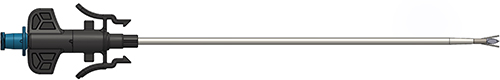 |
Figure 1 Subsidio™ RF Multitined Expandable Electrode. |
The main steps of the procedure are (1) Tap the introducer with trocar stylet into the pedicle. (2) Once docked in the pedicle, swap the trocar stylet for the bevel stylet and work from lateral to medial such that the tip of the stylet is approximately 0.75 cm ± 0.25 cm from the midline while being placed 30% - 50% anterior of the posterior wall of the vertebral body. (3) Swap the stylet for the device and deploy the tines. (4) Repeat placement for the opposite pedicle at the same vertebral level. (5) Insert the probes into the devices, connect to the RF generator and then run the proper ablation treatment protocol (85°C for 4 minutes) on the RF generator.
In this simulation study, the geometries for the 3D models were constructed from the CT scan images. Specifically, CT scan DICOM images were imported into 3D image segmentation and processing software. Semi-automatic segmentation was performed to define the bone margins of the vertebrae and sacrum (Figure 2). Detailed segmentations were performed on each vertebra to ensure that the correct morphological regions were selected (Figure 3). Finally, soft tissue segmentation was also performed to define the outlines of the skin, smoothing filters were applied and the full spine and skin 3D objects were exported as stereolithography (STL) files (Figure 4).
 |
Figure 2 Threshold segmentation is used to define the borders of the vertebrae and sacrum from computed tomography (CT) scan DICOM images. |
 |
Figure 3 Results of detailed image segmentation to enhance morphological identification. |
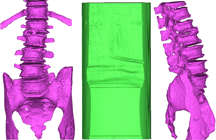 |
Figure 4 Full spine and skin 3D objects following application of smoothing filters. |
STL files were then imported into the 3D modeling software along with the CAD file of the electrode probe. The probe was patterned on the target zones with the aid of a cubic shaped template that included three orthogonal axes (Figure 5). The orthogonal axes were used to position the target zone relative to the vertebral body dimensions in the midline of the superior-inferior and the medial-lateral planes, and 60% towards posterior on the anterior-posterior plane (Figure 6). Targets were individually positioned on each vertebra within the region of interest (L1-S1 levels). Placeholder probe positioning trajectories were added to guide the positioning of the devices. Trajectories were generated using a set of points on the center of the cuboid target and the exterior surface/region of the pedicles. At this point, 3D renderings of the spine were changed to translucent so it was guaranteed that the positioning trajectories traveled through the center of each pedicle (Figure 7). Once the targets and axes were placed, the probe CAD file was patterned (x 12) and each of them aligned to their corresponding probe trajectory (Figure 8). Probes were individually rotated and translated around their pre-defined trajectories to position the tip of the cannula at the surface of the cuboid reference (Figure 9).
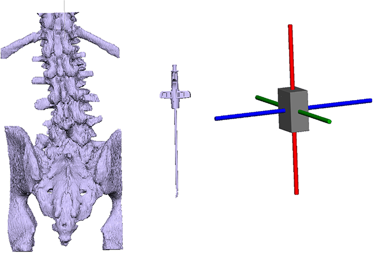 |
Figure 5 Imported 3D geometries (left, middle). Cuboid template with three orthogonal axes (right). |
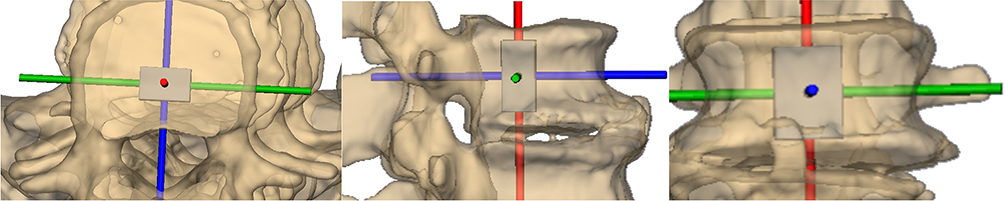 |
Figure 6 Target positioning within the vertebral body depicted in axial (a), sagittal (b), and anteroposterior (c) views. |
 |
Figure 7 Probe positioning axis. |
 |
Figure 8 Targets and positioning axes for the complete lumbosacral spine. |
 |
Figure 9 Example of probe placement. |
Device deployment simulations replicated the defined BVN plexus target zone as noted previously as midline in the anteroposterior view (ie, 50% superior-inferior, 50% medial-lateral) and approximately 40% across the vertebral body width from the posterior wall.24,25 The terminus of bilateral electrode deployment was to achieve alignment of the tines towards one another, projecting towards the midline with the tips of devices between 10 mm and 20 mm apart.26,27
After placing all the probes in each individual CT scan image set, the following measurements were obtained at each vertebral level: distance between tines, distance between cannula tips (Figure 10), functional distance (Figure 11), minimum contact distance between ipsilateral probes (Figure 12), and cannula angle (Figure 13). Specifically, the functional distance represented the distance from the cannula tip to the outer surface of the skin. The minimum distance between probes was measured on each pair of consecutive probes on both sides of the spine (eg, left L1 to left L2). The cannula angle included the angle between contralateral devices and the angle between each device and the sagittal plane.
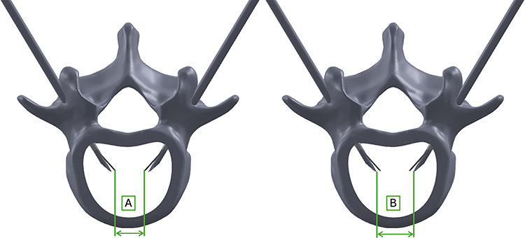 |
Figure 10 Distance between tines (A). Distance between cannula tips (B). |
 |
Figure 11 Functional distance between skin surface and cannula tip (C). |
 |
Figure 12 Minimum contact distance between probes on same anatomical side. |
 |
Figure 13 Cannula angles including the angle between each device and the sagittal plane (α) and the angle between devices (β). |
All measurement values are presented as means (± SD) and tabulated by vertebral level. For distance between cannula tips, values are also presented as frequency distributions based on successful targeting ≥ 10 mm to ≤ 20 mm distance. One-way analysis of variance was performed to compare the mean values of the normally distributed spinal dimensions (distances and angles) between the six vertebral levels assuming homogeneity of variance. The frequencies of successful reconstruction (indicated by distances between 10 mm to 20 mm) were analyzed using the Chi Square test. The effect sizes eta2 and Cramér’s V (95% confidence intervals, CI) were estimated to reflect the clinical relevance of the mean differences between the vertebral dimensions and the frequencies of successful reconstruction. The interpretation of the effect sizes, each of which could potentially range from 0 to 1 was as follows: 0.04 represented the “recommended minimum” in the context of clinical research; 0.05 to 0.24 represented a small effect with limited clinical relevance; 0.25 to 0.63 represented a “moderate” clinically relevant effect; and ≥ 0.64 represented a “large” clinically relevant effect.
Results
Figure 14 illustrates an example of an anatomical simulation of the lumbosacral region of interest derived from CT scan data with placement of fully-deployed probes at all vertebral levels and trajectories reflecting proper intraosseous positioning. Table 1 compares the distances between the tines with respect to the vertebral level. The mean distances ranged from 8.50 ± 1.2 mm (L5) to 9.24 ± 0.79 mm (L3). No statistically significance differences were found between the mean distances across the six vertebral levels (F = 1.67, p = 0.14). The effect size (eta2 = 0.05, 95% CI = 0.01, 0.13) reflected the limited clinical relevance of the differences between the mean distances.
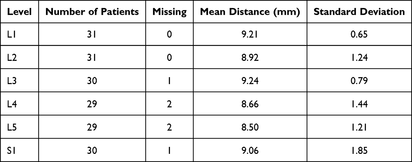 |
Table 1 Distance Between the Tines by Vertebral Level |
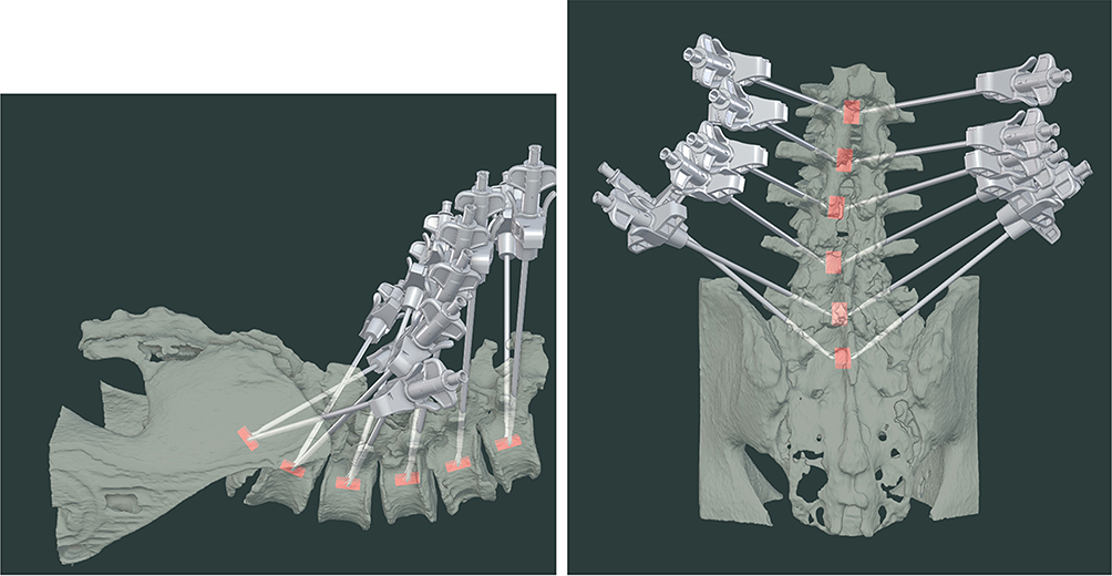 |
Figure 14 Computed tomography-derived anatomical simulation of the lumbosacral region of interest with placement and trajectories of fully-deployed probes at all vertebral levels. |
Table 2 compares the distances between the tips of the devices at each vertebral level. The mean distances ranged from 11.35 ± 1.53 mm (L5) to 11.87 ± 0.94 mm (L3). There were no statistically significance differences between the mean distances across the six vertebral levels (F = 0.72, p = 0.61). The effect size (eta2 = 0.02, 95% CI = 0.00, 0.08) reflected that the differences between the mean dimensions had little or no clinical relevance.
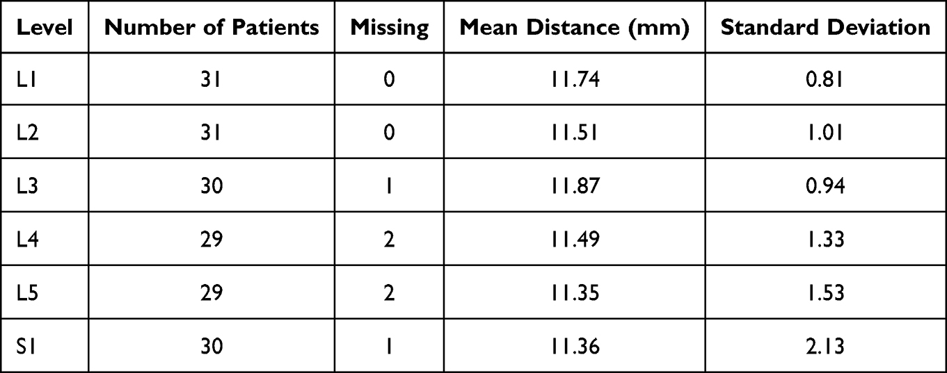 |
Table 2 Distance Between the Device Tips by Vertebral Level |
The histogram in Figure 15 (n=180 normally distributed measurements) shows that the distances between the cannula tips ranged from a minimum of 5.5 mm to a maximum of 16.1 mm. The percentage of successful CT reconstructions (ie, with distances of 10 mm to 20 mm between the tips) was 90% (162 of 180), with 10% (18 of 180) of reconstructions demonstrating a tip-to-tip distance of less than 10 mm which is clinically sufficient. None of the reconstructions had the tips too far apart (ie, > 20 mm). The percentage of the measurements within 1.0 mm of the 10 mm target was 6.9% (13 of 180) between 9.0 mm and 10.0 mm, and 15.0% (27 of 180) between 10.0 mm and 11.0 mm.
 |
Figure 15 Frequency distribution of distances (in mm) between cannula tips. |
The observed frequencies of successful reconstruction across the six vertebral levels reported in Table 3 ranged from 80.0% (24 of 30) at S1 to 96.8% (30 of 31) at L1. The observed proportions of successful reconstructions at each vertebral level were not statistically significant from the expected equal proportions at each vertebral level (χ2 = 1.33, p = 0.93). The effect size (Cramér’s V = 0.04, 95% CI = 0.01, 0.11) reflected that the differences between the observed and expected proportions of successful reconstructions at each vertebral level had little clinical relevance.
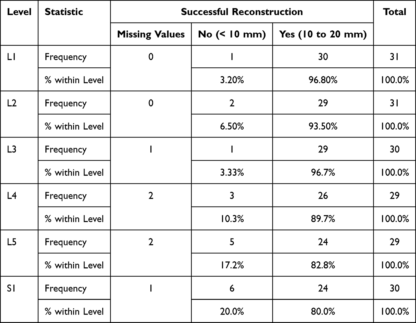 |
Table 3 Frequencies of Successful Reconstructions (10 to 20 Mm Distance Between Cannula Tips) |
Table 4 compares the functional distances from the tips of the left and right devices separately to the outer surface of the skin by vertebral level. The mean functional distances for the left devices ranged from 94.42 ± 13.92 mm (L1) to 127.40 ± 36.92 mm (L5). The mean functional distances between the six vertebral levels for the left-side devices were statistically significant (F = 3.80, p = 0.004) with a small to moderate effect size (eta2 = 0.18, 95% CI = 0.09, 0.29) reflecting the clinical relevance of the mean differences. The mean distances for the right devices ranged from 94.33 ± 13.81 mm (L1) to 127.03 ± 29.36 mm (L5). The mean functional distances between the six vertebral levels for the right-side devices were statistically significant (F = 3.87, p = 0.01). The small to moderate effect size (eta2 = 0.21, 95% CI = 0.11, 0.32) reflected the clinical relevance of the mean differences. The number of missing values increased substantially with decreasing vertebral level indicating that the skin surface was outside the zone of reconstruction so the functional distance could not be computed.
 |
Table 4 Functional Distances for Each Anatomical Side by Vertebral Level |
Table 5 compares the minimum contact distances on the left side of the spine by vertebral level. This table includes the negative values caused by overlap or interference with the adjacent ipsilateral probe as well as the positive values obtained by excluding all the negative values. The frequencies of overlap/interference were substantial. Negative values were observed in a total of 48.9% (88 of 180) of cases. The mean distances on the left side of the spine excluding negative values ranged from 11.38 ± 8.93 mm (L1 and S1) to 16.72 ± 13.12 mm (L2). No statistically significant differences were found between the mean distances across the six vertebral levels (F = 1.52, p = 0.19). The effect size (eta2 = 0.04. 95% CI = 0.00, 0.13) reflected little clinical relevance.
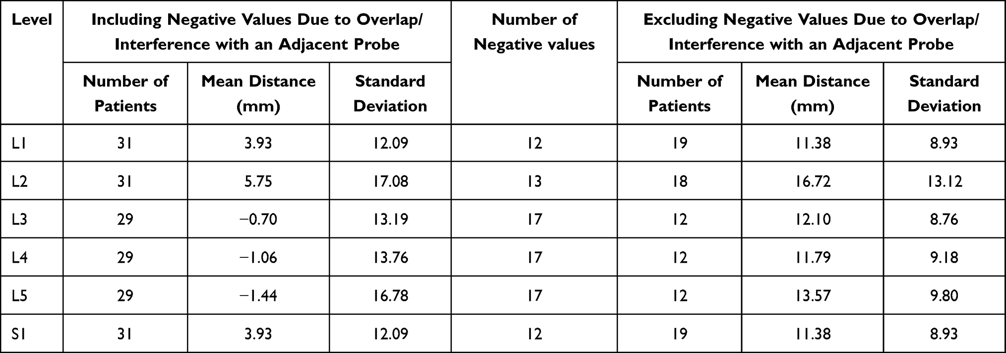 |
Table 5 Minimum/Contact Distance Between Devices: Left Side of Spine |
Table 6 compares the minimum contact distances on the right side of the spine across the six levels. This table includes the negative values caused by overlap/interference with the adjacent ipsilateral probe as well as the positive values obtained by excluding the reported number of negative values. The frequencies of overlap/interferences were substantial. Negative values were also observed in a total of 48.9% (88 of 180) of cases. The mean distances on the right side of the spine excluding negative values ranged from 9.42 ± 9.55 mm (L4) to 17.06 ± 9.34 mm (L1). No statistically significant differences were found between the mean distances across the six vertebral levels (F = 1.21, p = 0.31). The effect size (eta2 = 0.06. 95% CI = 0.00, 0.16) reflected little clinical relevance.
 |
Table 6 Minimum/Contact Distance Between Devices: Right Side of Spine |
Table 7 compares the angles of the cannula across the six vertebral levels. The mean device angle ranged widely from 50.90° ± 8.89° (L1) to 91.51° ± 12.96° (S1). A statistically significant difference between the device angles was found across the six vertebral levels (F = 89.5, p < 0.01) and the effect size was large (eta2 = 0.72. 95% CI = 0.64, 0.79).
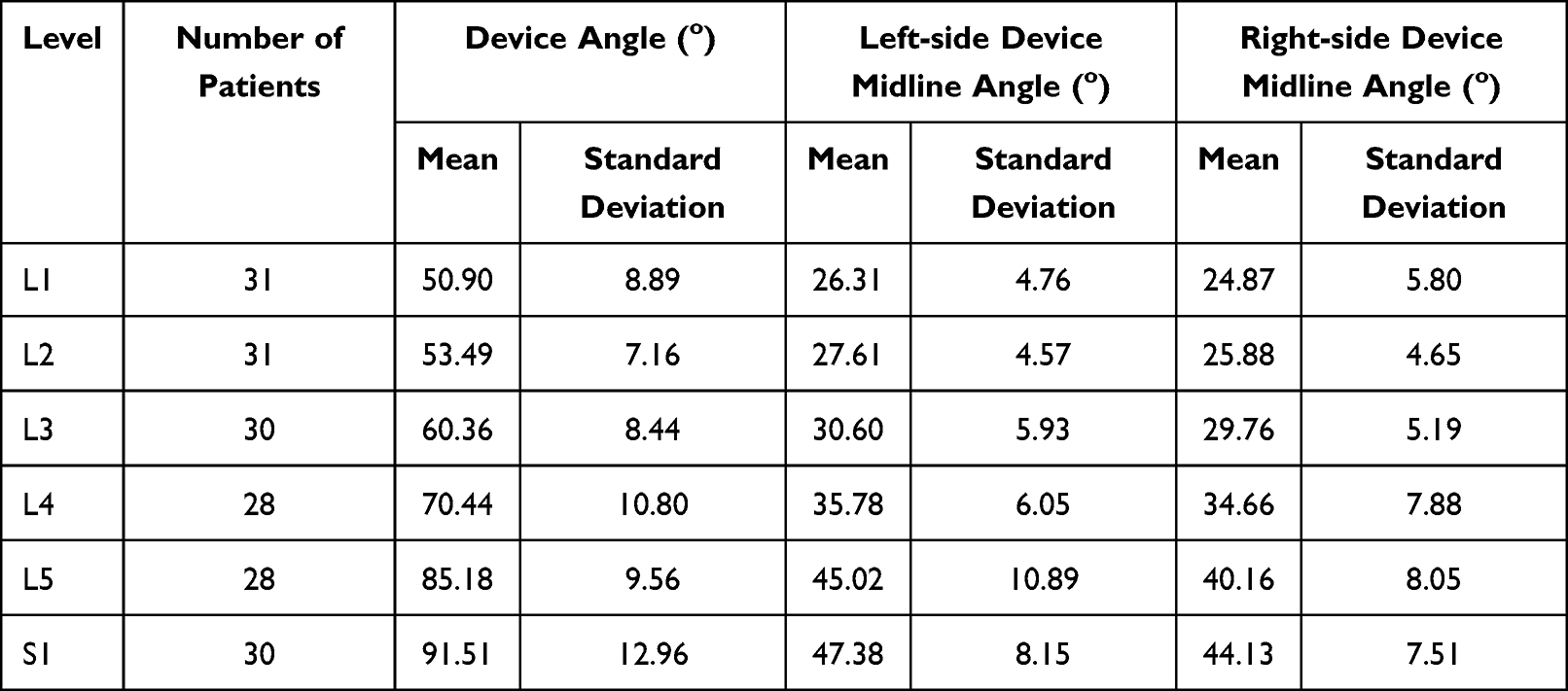 |
Table 7 Cannula Angles |
Table 7 also provides the mean left-side device midline angles, ranging from 26.31° ± 4.76° (L1) to 47.38° ± 8.15° (S1). A statistically significant difference between the left-side device midline angles was found across the six vertebral levels (F = 49.03, p < 0.01) and the effect size was moderate to large (eta2 = 0.59, 95% CI = 0.49, 0.67). The mean right-side device midline angles also ranged widely from 24.87° ± 5.80° (L1) to 44.13° ± 7.51° (S1), and a statistically significant difference was found between the right-side device midline angles across the six vertebral levels (F = 42.0, p < 0.01). The effect size was moderate (eta2 = 0.55, 95% CI = 0.45, 0.64). As shown in Table 7, the device angles increased systematically with decreasing vertebral level.
Discussion
This investigation builds on previous evidence of the feasibility of using the multitined electrode in bipolar configuration to allow for proper intraosseous placement within the vertebral body to effectively ablate the BVN plexus. Using a related, commercially-available predecessor RF device (Nimbus®, Stratus Medical), early clinical results in a limited numbers of patients with vertebrogenic pain have documented substantial and durable symptomatic improvement.28,29
In the current study, real world CT imaging data were utilized to reflect a wide range of body shapes and anatomic variety. Extrapolation from previous pre-clinical studies has identified that the ideal distance between electrode tips is between 10 and 20 mm to produce an adequately extensive zone of ablation to achieve clinical efficacy.26,27 We found that in 90% of our CT reconstructions the device tips could be placed within this distance threshold and, importantly, no tips were too far apart (ie, > 20 mm). Having the electrode tips < 10 mm also represents clinically sufficient placement as long as they do not touch.
There was a strong association between decreasing vertebral level and the ability to accurately measure the functional or working distance between the skin surface and the device tips (Table 4). At the S1 vertebral level, the functional distance was captured in only 10% of patients due to the skin surface being outside the CT zone of reconstruction. Thus, while inspection of the mean functional distance values (range: 94.3 mm to 127.4 mm) would suggest that both the 13 cm and 18 cm devices would accommodate most patients’ anatomies, additional investigation will be necessary to validate the appropriate device length for patients with a higher body mass index.
The complete CT reconstructions employed in this study illustrated full deployment of all devices simultaneously at every lumbosacral vertebral level (Figure 14). Under this circumstance, there was substantial overlap between the trajectories of adjacent ipsilateral devices due, in large part, to the progressive lumbar lordotic angle of the spine and patient-to-patient anatomical variation. We noted that approximately 50% of adjacent devices presented with trajectory overlap. This situation is reflected in the current clinical practice of not undertaking simultaneous BVN ablation at contiguous vertebral levels.
There was also a notable association between decreasing vertebral level and the degree of angulation between contralateral devices with the average device angle at S1 (91.5°) almost twice that at L1 (50.5°). Thus, to achieve proper intraosseous device placement in clinical practice, the cannula approach to the sacral vertebra needs to be far more lateral than at the caudal lumbar vertebral levels.12
These results correspond to the intended correct technique for this procedure when entering the pedicle and vertebral body. Specifically, one must work lateral to medial on the pedicle to achieve the proper docking position. In the oblique “Scotty Dog” view, the pedicle should be entered at the 3 o’clock or 9 o’clock position (depending on side) on the lateral aspect of the pedicle. Once docked, the bevel stylet will help drive the tip of the introducer medial in order to position the tips at the proper distance from the midline. We also noted a steep caudal angle at the S1 level which requires that remaining lateral is required to achieve proper placement. Anteroposterior, lateral, and trajectory fluoroscopic views will be used to confirm placement at all steps in the procedure.
Conclusions
With the identification of the vertebral endplates as a definitive source of chronic low back pain and the recognition that BVN ablation ameliorates these symptoms, it is important to develop, refine and validate new and additional devices to accomplish this procedure. The multitined electrode investigated in this study generates a more expansive ablation zone equating to a larger lesion volume than a conventional RF electrode. This would have the advantage of assuring complete thermal coagulation of the BVN plexus irrespective of factors that may compromise precise device placement such as patient anatomy and vertebral level. Additional pre-clinical and clinical research is encouraged to further validate this technology for treatment of vertebrogenic pain.
Data Sharing Statement
Requests for data sharing can be made by contacting the corresponding author. Individual participant data that underlie the results reported in this article will be made available (after deidentification) from 9 to 36 months after article publication. Data sharing will be limited to investigators whose proposed use of the data has been approved by an independent review committee identified for this purpose.
Ethics Approval and Informed Consent
This investigation was considered a secondary research study by the Institutional Review Board at the University of Kansas Medical Center, and granted an exemption from obtaining patient informed consent.
Acknowledgments
The authors appreciate the data management and statistical analysis support of Ron Fisher, Ph.D. Three-dimensional computational work was undertaken by Insight Surgical (Manchester, UK). Financial support for this work was provided by Neurovasis (Magnolia, TX, USA).
Author Contributions
All authors made a significant contribution to the work reported, whether that is in the conception, study design, execution, acquisition of data, analysis and interpretation, or in all these areas; took part in drafting, revising or critically reviewing the article; gave final approval of the version to be published; have agreed on the journal to which the article has been submitted; and agree to be accountable for all aspects of the work.
Disclosure
JEB is an independent advisor to Neurovasis and was remunerated for assistance in manuscript development. DPB is a consultant to Mesoblast, Discgenics, Spine Biorestorative, Orthoson and Vivex, has received research funding from Mesoblast, Discgenics, Spine Biorestorative and Vivex and is on the scientific advisory board of Orthoson, Vivex and Mesoblast. He also reports non-financial support from Medtronic, Merit Medical, Johnson & Johnson, IZI, Techlamed, Peterson Enterprises, Medical Metrics, Avanos, Boston Scientific, Simplify Medical, Stryker, Lenoss Medical, Spine BioPharma, Piramal, ReGelTec, Nanofuse, Spinal Simplicity, Pain Theory, Spark Biomedical, Bronx Medical, Smart Soft, Tissue Tech, RayShield, Stayble, Thermaquil, Vivex, Stratus Medical, Genesys, Abbott, Eliquence, SetBone Medical, Amber Implants, Cerapedics, Neurovasis, Varian Medical Systems, Companion Spine, DiscGenics, Discure, SpinaFX, PainTEQ, SI Bone, Orthoson, Choice Spine, Saluda Medical, Aurora Spine, Arts Surgical, AIS Healthcare, Wenzel Spine, grants from Medtronic, Medical Metrics, Avanos, Relievant, Boston Scientific, Stryker, Sollis Pharmaceuticals, Simplify Medical, Lenoss Medical, Spine BioPharma, Eliem Therapeutics, Smart Soft, Tissue Tech, Vivex, Stratus Medical, Restorative Therapies, Kolon TissueGene, Companion Spine, DiscGenics, SI Bone, Choice Spine, during the conduct of the study. EH reports personal fees from Neurovasis, during the conduct of the study; personal fees from Stratus Medical, outside the submitted work; In addition, Mr Eric Hyman has a patent pending to Neurovasis. The authors report no other conflicts of interest in this work.
References
1. Nicol V, Verdaguer C, Daste C, et al. Chronic low back pain: a narrative review of recent international guidelines for diagnosis and conservative treatment. J Clin Med. 2023;12(4):1685. doi:10.3390/jcm12041685
2. Ota Y, Connolly M, Srinivasan A, Kim J, Capizzano AA, Moritani T. Mechanisms and origins of spinal pain: from molecules to anatomy, with diagnostic clues and imaging findings. Radiographics. 2020;40(4):1163–1181. doi:10.1148/rg.2020190185
3. Sizer PS, Phelps V, Matthijs O. Pain generators of the lumbar spine. Pain Pract. 2001;1(3):255–273. doi:10.1111/j.1533-2500.2001.01027.x
4. Modic MT, Steinberg PM, Ross JS, Masaryk TJ, Carter JR. Degenerative disk disease: assessment of changes in vertebral body marrow with MR imaging. Radiology. 1988;166(1 Pt 1):193–199. doi:10.1148/radiology.166.1.3336678
5. Rajasekaran S, Bt P, Murugan C, et al. The disc-endplate-bone-marrow complex classification: progress in our understanding of Modic vertebral endplate changes and their clinical relevance. Spine J. 2024;24(1):34–45. doi:10.1016/j.spinee.2023.09.002
6. Viswanathan VK, Shetty AP, Rajasekaran S. Modic changes - An evidence-based, narrative review on its patho-physiology, clinical significance and role in chronic low back pain. J Clin Orthop Trauma. 2020;11(5):761–769. doi:10.1016/j.jcot.2020.06.025
7. Conger A, Smuck M, Truumees E, Lotz JC, DePalma MJ, McCormick ZL. Vertebrogenic pain: a paradigm shift in diagnosis and treatment of axial low back pain. Pain Med. 2022;23(Suppl 2):S63–S71. doi:10.1093/pm/pnac081
8. Lorio M, Clerk-Lamalice O, Rivera M, Lewandrowski KU. ISASS policy statement 2022: literature review of intraosseous basivertebral nerve ablation. Int J Spine Surg. 2022;16(6):1084–1094. doi:10.14444/8362
9. Lotz JC, Fields AJ, Liebenberg EC. The role of the vertebral end plate in low back pain. Global Spine J. 2013;3(3):153–164. doi:10.1055/s-0033-1347298
10. McCormick ZL, Conger A, Smuck M, et al. Magnetic resonance imaging characteristics associated with treatment success from basivertebral nerve ablation: an aggregated cohort study of multicenter prospective clinical trials data. Pain Med. 2022;23(Suppl 2):S34–S49. doi:10.1093/pm/pnac093
11. Bailey JF, Liebenberg E, Degmetich S, Lotz JC. Innervation patterns of PGP 9.5-positive nerve fibers within the human lumbar vertebra. J Anat. 2011;218(3):263–270. doi:10.1111/j.1469-7580.2010.01332.x
12. Degmetich S, Bailey JF, Liebenberg E, Lotz JC. Neural innervation patterns in the sacral vertebral body. Eur Spine J. 2016;25(6):1932–1938. doi:10.1007/s00586-015-4037-4
13. Conger A, Burnham TR, Clark T, Teramoto M, McCormick ZL. The Effectiveness Of Intraosseous Basivertebral Nerve Radiofrequency Ablation For The Treatment Of Vertebrogenic Low Back Pain: An Updated Systematic Review With Single-Arm Meta-analysis. Pain Med. 2022;23(Suppl 2):S50–S62. doi:10.1093/pm/pnac070
14. Fischgrund JS, Rhyne A, Macadaeg K, et al. Long-term outcomes following intraosseous basivertebral nerve ablation for the treatment of chronic low back pain: 5-year treatment arm results from a prospective randomized double-blind sham-controlled multi-center study. Eur Spine J. 2020;29(8):1925–1934. doi:10.1007/s00586-020-06448-x
15. Khalil JG, Smuck M, Koreckij T, et al. A prospective, randomized, multicenter study of intraosseous basivertebral nerve ablation for the treatment of chronic low back pain. Spine J. 2019;19(10):1620–1632. doi:10.1016/j.spinee.2019.05.598
16. Kim HS, Adsul N, Yudoyono F, et al. Transforaminal epiduroscopic basivertebral nerve laser ablation for chronic low back pain associated with Modic changes: a preliminary open-label study. Pain Res Manag. 2018;2018:6857983. doi:10.1155/2018/6857983
17. Koreckij T, Kreiner S, Khalil JG, et al. Prospective, randomized, multicenter study of intraosseous basivertebral nerve ablation for the treatment of chronic low back pain: 24-month treatment arm results. N Am Spine Soc J. 2021;8:100089. doi:10.1016/j.xnsj.2021.100089
18. Macadaeg K, Truumees E, Boody B, et al. A prospective, single arm study of intraosseous basivertebral nerve ablation for the treatment of chronic low back pain: 12-month results. N Am Spine Soc J. 2020;3:100030. doi:10.1016/j.xnsj.2020.100030
19. Nwosu M, Agyeman WY, Bisht A, et al. The effectiveness of intraosseous basivertebral nerve ablation in the treatment of nonradiating vertebrogenic pain: a systematic review. Cureus. 2023;15(4):e37114. doi:10.7759/cureus.37114
20. Smuck M, Khalil J, Barrette K, et al. Prospective, randomized, multicenter study of intraosseous basivertebral nerve ablation for the treatment of chronic low back pain: 12-month results. Reg Anesth Pain Med. 2021;46(8):683–693. doi:10.1136/rapm-2020-102259
21. Urits I, Noor N, Johal AS, et al. Basivertebral nerve ablation for the treatment of vertebrogenic pain. Pain Ther. 2021;10(1):39–53. doi:10.1007/s40122-020-00211-2
22. McCormick ZL, Curtis T, Cooper A, Wheatley M, Smuck M. Low back pain-related healthcare utilization following intraosseous basivertebral nerve radiofrequency ablation: a pooled analysis from three prospective clinical trials. Pain Med. 2024;25(1):20–32. doi:10.1093/pm/pnad114
23. Sayed D, Naidu RK, Patel KV, et al. Best practice guidelines on the diagnosis and treatment of vertebrogenic pain with basivertebral nerve ablation from the American Society of Pain and Neuroscience. J Pain Res. 2022;15:2801–2819. doi:10.2147/JPR.S378544
24. Tieppo Francio V, Sayed D. Basivertebral nerve ablation. In: StatPearls. Treasure Island (FL; 2024. StatPearls Publishing
25. Tieppo Francio V, Sherwood D, Twohey E, et al. Developments in minimally invasive surgical options for vertebral pain: basivertebral nerve ablation - a narrative review. J Pain Res. 2021;14:1887–1907. doi:10.2147/JPR.S287275
26. Ben-David E, Nissenbaum I, Gurevich S, Cosman ER, Goldberg SN. Optimization and characterization of a novel internally-cooled radiofrequency ablation system with optimized pulsing algorithm in an ex-vivo bovine liver. Int J Hyperthermia. 2019;36(2):81–88. doi:10.1080/02656736.2019.1617901
27. Solbiati L, Ierace T, Gennaro N, Muglia R, Cosman ER, Goldberg SN. Percutaneous radiofrequency ablation of HCC: reduced ablation duration and increased ablation size using single, internally cooled electrodes with an optimized pulsing algorithm. Int J Hyperthermia. 2020;37(1):861–867. doi:10.1080/02656736.2020.1790678
28. Buchanan G, Wright RE. Bipedicular basi-vertebral nerve ablation: a case report. Res Pract Anesthesiol Open J. 2021;5(1):8–13. doi:10.17140/RPAOJ-5-129
29. Mohabbati V, Mohabbati P, Papan M Basivertebral nerve ablation: a case series in chronic low back pain management.
 © 2024 The Author(s). This work is published and licensed by Dove Medical Press Limited. The
full terms of this license are available at https://www.dovepress.com/terms
and incorporate the Creative Commons Attribution
- Non Commercial (unported, 3.0) License.
By accessing the work you hereby accept the Terms. Non-commercial uses of the work are permitted
without any further permission from Dove Medical Press Limited, provided the work is properly
attributed. For permission for commercial use of this work, please see paragraphs 4.2 and 5 of our Terms.
© 2024 The Author(s). This work is published and licensed by Dove Medical Press Limited. The
full terms of this license are available at https://www.dovepress.com/terms
and incorporate the Creative Commons Attribution
- Non Commercial (unported, 3.0) License.
By accessing the work you hereby accept the Terms. Non-commercial uses of the work are permitted
without any further permission from Dove Medical Press Limited, provided the work is properly
attributed. For permission for commercial use of this work, please see paragraphs 4.2 and 5 of our Terms.
Recommended articles
Best Practice Guidelines on the Diagnosis and Treatment of Vertebrogenic Pain with Basivertebral Nerve Ablation from the American Society of Pain and Neuroscience
Sayed D, Naidu RK, Patel KV, Strand NH, Mehta P, Lam CM, Tieppo Francio V, Sheth S, Giuffrida A, Durkin B, Khatri N, Vodapally S, James CO, Westerhaus BD, Rupp A, Abdullah NM, Amirdelfan K, Petersen EA, Beall DP, Deer TR
Journal of Pain Research 2022, 15:2801-2819
Published Date: 14 September 2022
The American Society of Pain and Neuroscience (ASPN) Evidence-Based Clinical Guideline of Interventional Treatments for Low Back Pain
Sayed D, Grider J, Strand N, Hagedorn JM, Falowski S, Lam CM, Tieppo Francio V, Beall DP, Tomycz ND, Davanzo JR, Aiyer R, Lee DW, Kalia H, Sheen S, Malinowski MN, Verdolin M, Vodapally S, Carayannopoulos A, Jain S, Azeem N, Tolba R, Chang Chien GC, Ghosh P, Mazzola AJ, Amirdelfan K, Chakravarthy K, Petersen E, Schatman ME, Deer T
Journal of Pain Research 2022, 15:3729-3832
Published Date: 6 December 2022
Radiofrequency Ablation of the Medial Branch Nerves for Posterior Element Pain in Chronic Vertebral Compression Fractures: An Anatomical Review and Retrospective Case Series
Sanghvi CD, Gordon AT, Singh N, Willard FH, Ren Y, Wilson MD, Copenhaver D
Journal of Pain Research 2025, 18:6463-6475
Published Date: 2 December 2025