")
Back to Journals » International Journal of General Medicine » Volume 15
Biomechanical Effects of Pedicle Screw Positioning on the Surgical Segment in Models After Oblique Lumbar Interbody Fusion: An in-silico Study
Authors Xu C, Huang C, Cai P, Fang Z, Wei Z, Liu F, Li J, Liu Y
Received 3 December 2021
Accepted for publication 20 January 2022
Published 2 February 2022 Volume 2022:15 Pages 1047—1056
DOI https://doi.org/10.2147/IJGM.S352304
Checked for plagiarism Yes
Review by Single anonymous peer review
Peer reviewer comments 5
Editor who approved publication: Dr Scott Fraser
Chen Xu,1,* Chenyi Huang,2,* Ping Cai,3 Zhongxin Fang,4 Zhangchao Wei,2 Fei Liu,2 Jingchi Li,1,2 Yang Liu1
1Department of Spine Surgery, Shanghai Changzheng Hospital, Naval Medical University, Shanghai, 200003, People’s Republic of China; 2Department of Orthopedics, Hospital (T.C.M) Affiliated to Southwest Medical University, Luzhou, 646000, Sichuan, People’s Republic of China; 3Department of Orthopedics, Affiliated Hospital of Nanjing University of Chinese Medicine, Nanjing, Jiangsu, People’s Republic of China; 4Fluid and Power Machinery Key Laboratory of Ministry of Education, Xihua University, Chengdu, People’s Republic of China
*These authors contributed equally to this work
Correspondence: Yang Liu
Department of Spine Surgery, Shanghai Changzheng Hospital, Naval Medical University, 415th Fengyang Road, Shanghai, 200003, People’s Republic of China
, Email [email protected]
Jingchi Li
Department of Orthopedics, Hospital (T.C.M) Affiliated to Southwest Medical University, No. 182, Chunhui Road, Luzhou, Sichuan Province, 646000, People’s Republic of China
, Email [email protected]
Background: Bilateral pedicle screw (BPS) is the “gold standard” of fixation methods for patients with lumbar interbody fusion. Biomechanical deterioration initially triggers complications in the surgical segment. Studies proved that BPS positions and trajectory changes affect the local biomechanical environment. However, no study illustrates the biomechanical effect of insertional screw positions’ change on the surgical segment.
Methods: Oblique lumbar interbody fusion (OLIF) with different BPS insertional positions has been simulated in a well-validated lumbo-sacral model. Fixation stability and stress responses on the surgical segment were evaluated under identical loading conditions.
Results: There is no clear variation tendency for the risk of BPS failure and the change of strain energy density of the grafted bone. However, shifting the insertional screw position close to the surgical segment will increase the range of motions (ROM) in the surgical segment and lead to stress concentration of bony structures, especially in the caudal side of the surgical segment.
Conclusion: Adjusting the insertional position of BPS close to the surgical segment in OLIF models will lead to stress concentration of bony structures and surgical segmental instability. Therefore, reducing BPS’s fixation length was not recommended, which may increase the risk of segmental instability, non-union, and cage subsidence.
Keywords: oblique lumbar interbody fusion, bilateral pedicle screw, cage subsidence, insertional screw positions, non-union
Introduction
Lumbar interbody fusion (LIF) operations have been widely used to treat lumbar degenerative diseases (LDD).1,2 By transpedicular three-column fixation, bilateral pedicle screw (BPS) could provide the best fixation stability compared with other additional fixation devices.3,4 Surgical segment complications (eg, cage subsidence, non-union, and BPS failures) will negatively affect LIF patients’ prognosis.2,5 Biomechanical deteriorations initially trigger these complications.6–8 Studies reported that screw insertional positions and trajectories would affect the local biomechanical environment.9–11
Recently, the oblique lumbar interbody fusion (OLIF) has been rapidly promoted.1,2 Compared with posterior approach LIF operations, the large footprint of OLIF cage is less likely to result in cage subsidence, but considering the indirect nerve structures’ decompression is entirely rely on the distraction of disc space, the negative effect on patient’s prognosis is pronounced in OLIF than other posterior approach LIF patients.1,5,7,12 Percutaneous BPS fixation is widely used in OLIF operations. In this process, the insertional screw positions are highly adjustable under C-arm radiography guidance. Insertional positions’ changes will affect the fixation length of BPS, resulting in changes in surgical segment stiffness and local stress distribution that may impact the risk of complications on the surgical segment.3,11,13 Thus, mechanical effects of insertional screw position’s change on the surgical segment should be elucidated to optimize this surgical strategy and reduce complication risk. In this study, using a highly biomimetic lumbo-sacral model, BPS fixation with different insertional screw positions has been simulated, and mechanical indicators related to complications in the surgical segment have been computed and recorded. Published literature has not adequately clarified this issue to the best of our knowledge.
Methods
Model Construction
Our previously published studies have constructed and validated highly biomimetic in-vitro data based finite element (FE) model (L3-S1). Bone structures of this model include cortical, cancellous, and bony endplates (BEP).14,15 The cortical thickness was set as 0.8 mm, the thickness, concave angle, and depth of superior and inferior BEPs were defined separately according to measured values from large sample anatomic studies. Nonbony components include the intervertebral disc (IVD) and facet cartilages. IVD consists of the nucleus core, the surrounding annulus, and cartilage endplates (CEP).14,15 BEPs’ outlines cover the entire IVD, and that of CEP was set on the cranial and caudal sides of the nucleus and inner part of the annulus. Based on the MRI data measurement, the nucleus’s cross-sectional area accounted for 38% of the IVD.14,15
The L4-L5 segment was selected to simulate the anterior psoas approach oblique lumbar interbody fusion (OLIF) fixed by BPS with different insertional screw positions. In the surgical simulation processes, lateral parts of the annulus, all of the nucleus, and CEPs were removed, and a polyether-ether-ketone (PEEK) OLIF cage (18 mm width and 50 mm length) filled with grafted bone was inserted into the interbody space.16,17 Cage and BEP were assumed to be completely matched. The lordotic angle and disc height of postoperative models were identical to the preoperative model.13,17,18
During the simulation of BPS fixation, four identical titanium alloy pedicle screws (diameter: 6mm, length: 45 mm) were inserted into L4-L5 vertebral bodies. The axes of screws in the transverse plane were parallel to the pedicle axis, which in the sagittal plane was parallel to the BEP in the cranial side.19,20 Screw threads were preserved, and the screw compaction effect was simulated by adjusting the material property of cancellous around the thread.13,20,21 The connection between the screw tulip and the nut was simplified to increase the computational efficiency. By adjusting insertional positions in different vertebral bodies, five models with different fixation lengths of BPS were simulated (Figure 1).
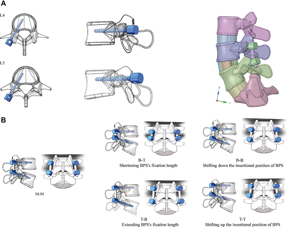 |
Figure 1 Diagrams of surgical simulations in this study. (A) BPS fixation with different fixation lengths and screw positions. M-M: Screws were inserted into the middle positions of both cranial and caudal vertebral bodies; B-T: Screws were inserted into the bottom of the cranial and the top of the caudal vertebral bodies (Shortest fixation length of PFS); T-B: Screws were inserted into the top of the cranial and the bottom of the caudal vertebral bodies (Longest fixation length of PFS); BB: Screws were inserted into the bottom of both cranial and caudal vertebral bodies (The downward movement of PFS); TT: Screws were inserted into the top of both cranial and caudal vertebral bodies (The upward movement of PFS). (B) Screw trajectories in the transverse and sagittal planes, and cage’s position in postoperative models. |
Boundary and Loading Conditions
Hybrid meshes with different sizes were set in different components. Mesh refinement was set in structures with low thickness and large deformation (eg, BEP, facet cartilage, and posterior parts of the annulus).14,15 In the definition of material properties, cortical and cancellous bone were defined by anisotropic law,22,23 other components of these models were defined by isotropic law. The annulus was assumed to be hypoelastic material, and the nucleus was set as a semi-fluid incompressible material.24,25 Ligaments and facet capsules were defined as cable elements. The frictional coefficient between facet cartilages, cage and BEP, and screw-cancellous interfaces were set as 0, 0.8, and 0.2, respectively.26,27
Inferior surfaces of models were fixed entirely, all moments in different directions were applied on the superior endplate of models.14,15 Mechanical indicators were computed under four different loading conditions, including 8 Nm flexion, 6Nm extension, 6Nm bending, and 4Nm rotation.18,28 In this process, models are set to be symmetrical along the sagittal plane to increase their computational efficiency by allowing the unilateral calculation of the bending and axial rotation loading conditions.14,15
Model Calibration and Validation
ROMs in the L4-L5 segment were seen as the reference of model calibration. The stiffness of ligaments under different loading conditions was calibrated to reduce the difference between the computed and in-vitro measured values.29,30 We performed a mesh convergence test on the calibrated intact model by evaluating the change of intradiscal pressure (IDP) with different mesh sizes. The model was considered converged if the change of computed IDP was less than 3%. Then, to ensure computational credibility, multi-indicator model validation has been accomplished.31,32 In this process, the computed ROM and DC were compared with measured values from in-vitro studies reported by Renner et al, IDP was compared with values measured by Schilling et al, and which of FCF were also compared with Wilson et al’s study.33–35
Results
Multi-Indicator Model Validation
Computational results of multi-indicator model validation show that the intact model with calibrated ligamentum stiffness could make good representations of the actual mechanical environment. These mechanical indicators computed by the calibrated intact model were within ±1 standard deviation of the average values measured by in-vitro studies (Figure 2).
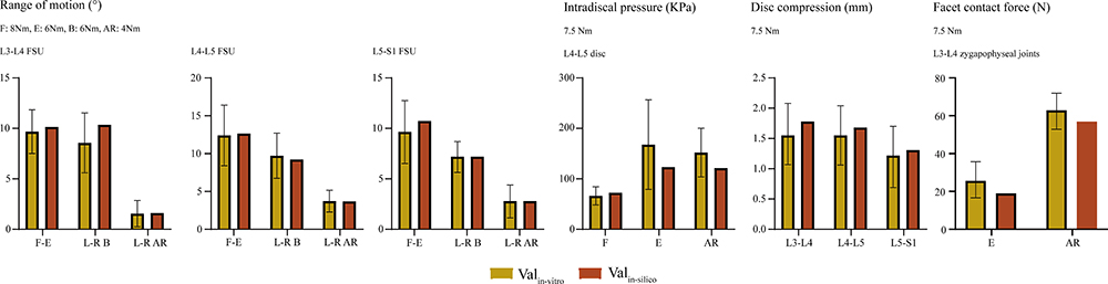 |
Figure 2 Multi-indicator model validation. |
Mechanical Effects of Insertional Screw Position’s Changes
Mechanical indicators were computed to evaluate the risk of complications in the surgical segment. We measured the surgical segment range of motions (ROM) to investigate the fixation stability and the risk of non-union. Positive correlations between PFS’s fixation length and stiffness were recorded (Figure 3). Shifting BPS to the caudal side can also increase surgical segment stiffness under the same fixation length. The grafted bone’s strain energy density (SED) was also computed to identify the non-union risk, and the maximum von-Mises stress on BPS was computed to investigate the risk of BPS failure (Figure 3). With the change of fixed length and insertional screw positions, no apparent variation tendency can be observed for SED. By contrast, the maximum stress of BPS increased whether the screw was shifted upward or downward from the middle of the pedicle.
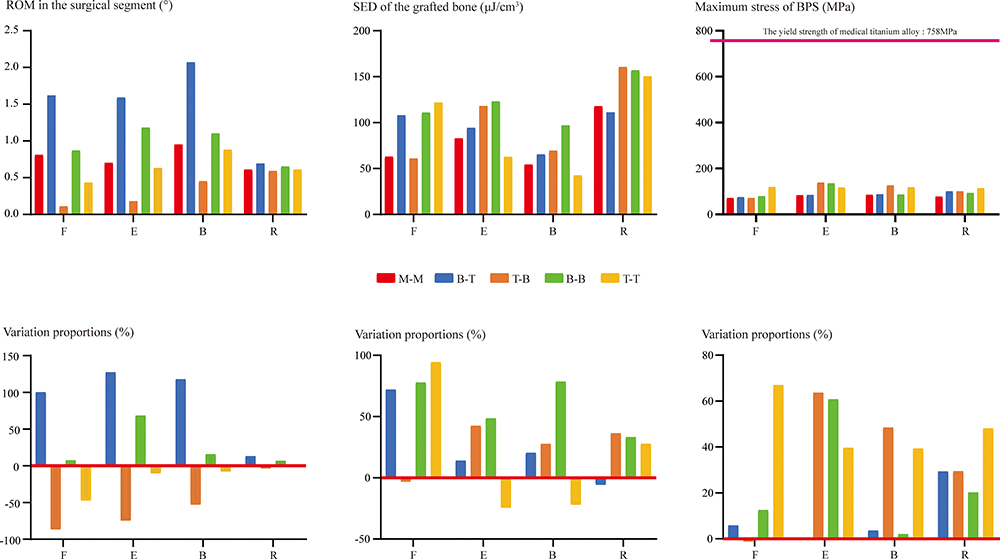 |
Figure 3 ROM in the surgical segment, SED of the grafted bone, and the maximum von-Mises stress on BPS. Abbreviations: F, flexion; E, extension; B, bending; R, axial rotation. |
Additionally, maximum stress on the BEP and subendplate cancellous bone (cancellous bone within 5mm of the BEP, SCB) was also recorded to evaluate the risk of cage subsidence.36,37 The evident variation tendency of this indicator can be observed with the insertional screw position’s change. Specifically, when the screw position is close to the surgical segment (shifting down of screw on the cranial side and shifting up of screw on the caudal side), stress concentration occurs in these bony structures (Figure 4). The most significant change can be observed in the inferior SCB. When the insertional position of the caudal screw shifted up, the maximum stress of inferior BEP and SCB increased dramatically under all loading conditions. More importantly, the maximum stress is close to or even higher than the average yield strength of cancellous bone (2.37 Mpa) under some loading conditions (Figure 5).19,38
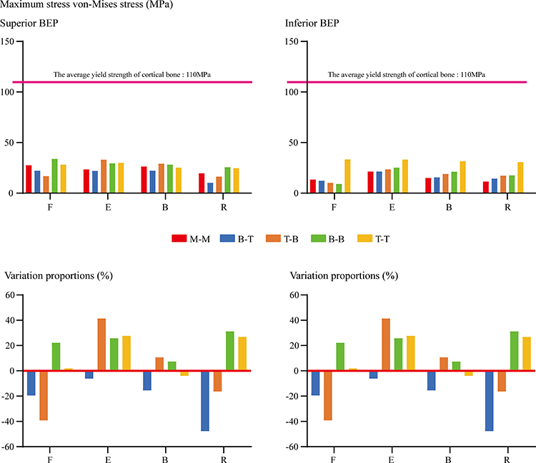 |
Figure 4 The maximum von-Mises stress on BEP. |
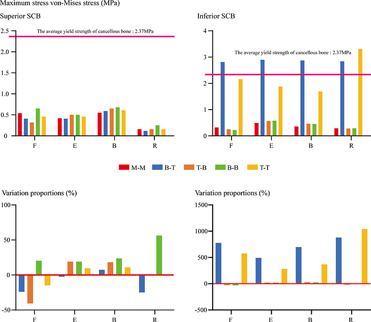 |
Figure 5 The maximum von-Mises stress on SCB. |
Discussion
Biomechanical deteriorations initially trigger surgical segment complications.6–8 Relations between screw positions and biomechanical environments have been widely reported.9–11 This study has numerically investigated the effects of screw insertional position changes, and biomechanical indicators related to surgical segment complications (ie, cage subsidence, non-union, segmental instability, and fixation failure) have been computed and recorded. Modifying the surgical strategy based on these computational results may be an effective method to optimize patients’ prognoses.
Segmental instability and non-union could trigger segmental instability and the recurrence of low back pain. The SED of the grafted bone was proved to be a credible predictor of osteogenesis by mechanical and clinical studies,39,40 fixation stability of the surgical segment was also important for the osteointegration process,41,42 and the surgical segment’s ROM a reliable indicator when evaluating fixation stability.43–45 In this study, the SED of grafted bone did not show a clear variation tendency with the change of screw position. By contrast, the surgical segment’s ROM increased with the reduction of fixation length. Therefore, we can deduce that reducing fixation length by changing insertional screw positions may increase the risk of segmental instability and non-union.
Besides, aberrant stress concentration in the BPS may lead to its failure, and in turn, negatively affect the surgical segment’s stability and impede interbody bone integration.20,46 The increase of maximum stress can be observed when shifting up and down the BPS from the middle of the pedicle. Variations in the length of screws that were not inserted into the vertebra could explain this phenomenon, which may be related to the length of screws that do not insert into the vertebral body. Specifically, mechanical studies show that uniform stress distribution is achieved when the screw is fully inserted into the vertebral body,20,47,48 no matter which direction the insertional screw position shifts from the middle position of the pedicle, the length of screws that do not insert into the vertebral body will be increased (Figure 6). This may be an initial trigger of stress concentration in BPS. Considering the maximum stress’s value was far less than the yield strength of medical titanium alloy (758 Mpa),20,49 we believe that the change of insertional screw positions and BPS’s fixation length will not significantly affect the risk of non-fusion and BPS failure.
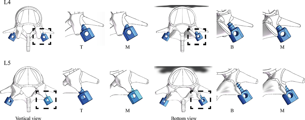 |
Figure 6 The relation between insertional screw positions and threads-bone integration. No matter which direction the insertional screw position shifts from the middle position of the pedicle, the length of screws that do not insert into the vertebral body will be increased. |
More significantly, aberrant stress concentration in the BEP and SCB will damage these bony structures and increase the risk of cage subsidence; evident stress concentration in bony structures can be observed when the screw position is close to the surgical segment, especially for the inferior BEP and SCB.5,49 According to the principle of stress concentration, a structure with high stiffness will bear a greater load. Therefore, BPS and its surrounding bony structures will be subjected to higher stress than other structures. Distances between the pedicle screw to BEP and SCB were larger in the cranial side, and the tendency of stress concentration of these bony structures was relatively slight. By contrast, when shifting up the insertional screw position of the caudal pedicle screw, the screw trajectory will be placed in the SCB of the inferior vertebral body. Thus, the apparent stress concentration of SCB and BEP can be recorded. The risk of SCB’s micro-damage may be increased dramatically under this mechanical circumstance, especially when the maximum value is higher than its yield strength,19,38 and the damage to SCB will lead to the loss of the subendplate mechanical support.45,50 This pathological change may be an even more important cause of cage subsidence in contrast to the damage to BEPs.36,37 By contrast, although stress concentration can also be observed in BEP, considering the maximum stress was still less than the yield stress of BEP (110 Mpa),19,38 the risk of BPE fracture may be increased slightly not (Figure 7).
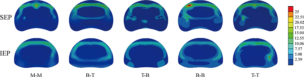 |
Figure 7 Nephograms of stress distribution on BEP under flexion loading condition. |
The current study still faces some limitations. Firstly, we set ligaments as cable elements in current FE models. The mechanical effect of cables can only be acted on artificially selected positions rather than their original surfaces. Additionally, fibrosis scar tissues around the excision of the annulus and its mechanical effect were omitted in this study. Although the resulting potential risk of mechanical indicator distortions should be considered, we still believe that the computational results in this study are reliable for the following reasons. Firstly, the model construction strategy with these limitations was widely accepted.18,28,51 Meanwhile, no attach positions of cable elements are defined on structures whose mechanical indicators were recorded in this study. Thus, even if there is computational distortion, it can be excluded from the indicator’s computation. More significantly, the intact model used in this study was validated and accepted in the studies mentioned above. These limitations should be optimized in our future in-silico studies.
Based on these computational results, we believe that the reduction of fixation length by changing insertional positions of BPS was not recommended for the insertional screw strategy and may increase the risk of segmental instability, non-union, and cage subsidence. Conclusions based on the biomechanical change should be revalidated in our further clinical studies.
Conclusions
Adjusting the insertional position of BPS close to the surgical segment in OLIF models will lead to stress concentration of bony structures and surgical segmental instability. Therefore, reducing BPS’s fixation length was not recommended, which may increase the risk of segmental instability, non-union, and cage subsidence. However, these conclusions should be validated in our future clinical studies.
Abbreviations
BEP, bony endplate; BPS, bilateral pedicle screw; CEP, cartilage endplate; DC, disc compression; IDP, intradiscal pressure; IVD, intervertebral disc; LDD, lumbar degenerative diseases; LIF, lumbar interbody fusion; OLIF, oblique lumbar interbody fusion; ROM, range of motions; SCB, subendplate cancellous bone; SED, strain energy density.
Data Sharing Statement
All the data of the manuscript are presented in the paper.
Acknowledgments
We acknowledge Mr. Xiaoyu Zhang for the guidance of figures preparation.
Author Contributions
All authors made a significant contribution to the work reported, whether that is in the conception, study design, execution, acquisition of data, analysis and interpretation, or in all these areas; took part in drafting, revising or critically reviewing the article; gave final approval of the version to be published; have agreed on the journal to which the article has been submitted; and agree to be accountable for all aspects of the work:
Conception and design: Yangliu, Jingchi Li, and Chen Xu;
Model construction and finite element analysis: Jingchi Li, Chen Xu and Zhongxin Fang;
Analysis and interpretation of data: Chenyi Huang, Jingchi Li, Chen Xu and Ping Cai;
Figures preparation: Chenyi Huang, Jingchi Li, Fei Liu and Zhangchao Wei;
Manuscript Preparation: Chen Xu, Chenyi Huang and Jingchi Li;
Manuscript modification: Yang Liu.
Funding
This research was supported by grants from the National Natural Science Foundation of China (81972090, 82172470, and 82072471), Shanghai Science & Technology Commission Rising-Star Program (20QA1409200) and Biopharmaceutical science and technology supporting foundation (21S31901400), Shanghai Changzheng Hospital Medical Service Innovation Project (2020CZWJFW15) and High-Quality Research Cultivating Project (2020YCGPZ-207).
Disclosure
The authors declare that they have no competing interests.
References
1. Li JX, Phan K, Mobbs R. Oblique lumbar interbody fusion: technical aspects, operative outcomes, and complications. World Neurosurg. 2017;98:113–123. doi:10.1016/j.wneu.2016.10.074
2. Woods KR, Billys JB, Hynes RA. Technical description of oblique lateral interbody fusion at L1-L5 (OLIF25) and at L5-S1 (OLIF51) and evaluation of complication and fusion rates. Spine J. 2017;17:545–553. doi:10.1016/j.spinee.2016.10.026
3. Hsieh YY, Chen CH, Tsuang FY, Wu LC, Lin SC, Chiang CJ. Removal of fixation construct could mitigate adjacent segment stress after lumbosacral fusion: a finite element analysis. Clin Biomech. 2017;43:115–120. doi:10.1016/j.clinbiomech.2017.02.011
4. Lee MJ, Lindsey JD, Bransford RJ. Pedicle screw-based posterior dynamic stabilization in the lumbar spine. J Am Acad Orthop Surg. 2010;18:581–588. doi:10.5435/00124635-201010000-00001
5. Oh KW, Lee JH, Lee JH, Lee DY, Shim HJ. The correlation between cage subsidence, bone mineral density, and clinical results in posterior lumbar interbody fusion. Clin Spine Surg. 2017;30:E683–e689. doi:10.1097/BSD.0000000000000315
6. Faizan A, Kiapour A, Kiapour AM, Goel VK. Biomechanical analysis of various footprints of transforaminal lumbar interbody fusion devices. J Spinal Disord Tech. 2014;27:E118–127. doi:10.1097/BSD.0b013e3182a11478
7. Xi Z, Mummaneni PV, Wang M, et al. The association between lower Hounsfield units on computed tomography and cage subsidence after lateral lumbar interbody fusion. Neurosurg Focus. 2020;49:E8. doi:10.3171/2020.5.FOCUS20169
8. Zhang Z, Fogel GR, Liao Z, Sun Y, Liu W. Biomechanical analysis of lumbar interbody fusion cages with various lordotic angles: a finite element study. Comput Methods Biomech Biomed Engin. 2018;21:247–254. doi:10.1080/10255842.2018.1442443
9. Newcomb AG, Baek S, Kelly BP, Crawford NR. Effect of screw position on load transfer in lumbar pedicle screws: a non-idealized finite element analysis. Comput Methods Biomech Biomed Engin. 2017;20:182–192. doi:10.1080/10255842.2016.1209187
10. Amirouche F, Solitro GF, Magnan BP. Stability and spine pedicle screws fixation Strength-A comparative study of bone density and insertion angle. Spine Deform. 2016;4:261–267. doi:10.1016/j.jspd.2015.12.008
11. La Barbera L, Costa F, Villa T. ISO 12189 standard for the preclinical evaluation of posterior spinal stabilization devices–II: a parametric comparative study. Proc Inst Mech Eng H. 2016;230:134–144. doi:10.1177/0954411915621588
12. Abe K, Orita S, Mannoji C, et al. Perioperative complications in 155 patients who underwent oblique lateral interbody fusion surgery: perspectives and indications from a retrospective, multicenter survey. Spine. 2017;42:55–62. doi:10.1097/BRS.0000000000001650
13. Guo HZ, Tang YC, Guo DQ, et al. Stability evaluation of oblique lumbar interbody fusion constructs with various fixation options: a finite element analysis based on three-dimensional scanning models. World Neurosurg. 2020;138:e530–e538. doi:10.1016/j.wneu.2020.02.180
14. Li J, Xu C, Zhang X, et al. TELD with limited foraminoplasty has potential biomechanical advantages over TELD with large annuloplasty: an in-silico study. BMC Musculoskelet Disord. 2021;22:616. doi:10.1186/s12891-021-04504-1
15. Li J, Xu C, Zhang X, et al. Disc measurement and nucleus calibration in a smoothened lumbar model increases the accuracy and efficiency of in-silico study. J Orthop Surg Res. 2021;16:498. doi:10.1186/s13018-021-02655-4
16. Lu T, Lu Y. Comparison of biomechanical performance among posterolateral fusion and transforaminal, extreme, and oblique lumbar interbody fusion: a finite element analysis. World Neurosurg. 2019;129:e890–e899. doi:10.1016/j.wneu.2019.06.074
17. Wang B, Hua W, Ke W, et al. Biomechanical evaluation of transforaminal lumbar interbody fusion and oblique lumbar interbody fusion on the adjacent segment: a finite element analysis. World Neurosurg. 2019;126:e819–e824. doi:10.1016/j.wneu.2019.02.164
18. Kim HJ, Chun HJ, Kang KT, et al. The biomechanical effect of pedicle screws’ insertion angle and position on the superior adjacent segment in 1 segment lumbar fusion. Spine. 2012;37:1637–1644. doi:10.1097/BRS.0b013e31823f2115
19. Liu JM, Zhang Y, Zhou Y, et al. The effect of screw tunnels on the biomechanical stability of vertebral body after pedicle screws removal: a finite element analysis. Int Orthop. 2017;41:1183–1187. doi:10.1007/s00264-017-3453-y
20. Chao CK, Hsu CC, Wang JL, Lin J. Increasing bending strength and pullout strength in conical pedicle screws: biomechanical tests and finite element analyses. J Spinal Disord Tech. 2008;21:130–138. doi:10.1097/BSD.0b013e318073cc4b
21. Hsu CC, Chao CK, Wang JL, Hou SM, Tsai YT, Lin J. Increase of pullout strength of spinal pedicle screws with conical core: biomechanical tests and finite element analyses. J Orthop Res. 2005;23:788–794. doi:10.1016/j.orthres.2004.11.002
22. Morgan EF, Bayraktar HH, Keaveny TM. Trabecular bone modulus-density relationships depend on anatomic site. J Biomech. 2003;36:897–904. doi:10.1016/S0021-9290(03)00071-X
23. Tsouknidas A, Sarigiannidis SO, Anagnostidis K, Michailidis N, Ahuja S. Assessment of stress patterns on a spinal motion segment in healthy versus osteoporotic bony models with or without disc degeneration: a finite element analysis. Spine J. 2015;15:S17–s22. doi:10.1016/j.spinee.2014.12.148
24. Wu HC, Yao RF. Mechanical behavior of the human annulus fibrosus. J Biomech. 1976;9:1–7. doi:10.1016/0021-9290(76)90132-9
25. Newell N, Little JP, Christou A, Adams MA, Adam CJ, Masouros SD. Biomechanics of the human intervertebral disc: a review of testing techniques and results. J Mech Behav Biomed Mater. 2017;69:420–434. doi:10.1016/j.jmbbm.2017.01.037
26. Polikeit A, Ferguson SJ, Nolte LP, Orr TE. Factors influencing stresses in the lumbar spine after the insertion of intervertebral cages: finite element analysis. Eur Spine J. 2003;12:413–420. doi:10.1007/s00586-002-0505-8
27. Zhong ZM, Deviren V, Tay B, Burch S, Berven SH. Adjacent segment disease after instrumented fusion for adult lumbar spondylolisthesis: incidence and risk factors. Clin Neurol Neurosurg. 2017;156:29–34. doi:10.1016/j.clineuro.2017.02.020
28. Kim HJ, Kang KT, Son J, Lee CK, Chang BS, Yeom JS. The influence of facet joint orientation and tropism on the stress at the adjacent segment after lumbar fusion surgery: a biomechanical analysis. Spine J. 2015;15:1841–1847. doi:10.1016/j.spinee.2015.03.038
29. Schmidt H, Heuer F, Simon U, et al. Application of a new calibration method for a three-dimensional finite element model of a human lumbar annulus fibrosus. Clin Biomech. 2006;21:337–344. doi:10.1016/j.clinbiomech.2005.12.001
30. Schmidt H, Heuer F, Drumm J, Klezl Z, Claes L, Wilke HJ. Application of a calibration method provides more realistic results for a finite element model of a lumbar spinal segment. Clin Biomech. 2007;22:377–384. doi:10.1016/j.clinbiomech.2006.11.008
31. Fan W, Guo LX, Zhang M. Biomechanical analysis of lumbar interbody fusion supplemented with various posterior stabilization systems. Eur Spine J. 2021;30:2342–2350. doi:10.1007/s00586-021-06856-7
32. Ottardi C, Galbusera F, Luca A, et al. Finite element analysis of the lumbar destabilization following pedicle subtraction osteotomy. Med Eng Phys. 2016;38:506–509. doi:10.1016/j.medengphy.2016.02.002
33. Renner SM, Natarajan RN, Patwardhan AG, et al. Novel model to analyze the effect of a large compressive follower pre-load on range of motions in a lumbar spine. J Biomech. 2007;40:1326–1332. doi:10.1016/j.jbiomech.2006.05.019
34. Schilling C, Krüger S, Grupp TM, Duda GN, Blömer W, Rohlmann A. The effect of design parameters of dynamic pedicle screw systems on kinematics and load bearing: an in vitro study. Eur Spine J. 2011;20:297–307. doi:10.1007/s00586-010-1620-6
35. Wilson DC, Niosi CA, Zhu QA, Oxland TR, Wilson DR. Accuracy and repeatability of a new method for measuring facet loads in the lumbar spine. J Biomech. 2006;39:348–353. doi:10.1016/j.jbiomech.2004.12.011
36. Okano I, Jones C, Salzmann SN, et al. Endplate volumetric bone mineral density measured by quantitative computed tomography as a novel predictive measure of severe cage subsidence after standalone lateral lumbar fusion. Eur Spine J. 2020;29:1131–1140. doi:10.1007/s00586-020-06348-0
37. Brier-Jones JE, Palmer DK, Ĭnceoğlu S, Cheng WK. Vertebral body fractures after transpsoas interbody fusion procedures. Spine J. 2011;11:1068–1072. doi:10.1016/j.spinee.2011.07.020
38. Zhao FD, Pollintine P, Hole BD, Adams MA, Dolan P. Vertebral fractures usually affect the cranial endplate because it is thinner and supported by less-dense trabecular bone. Bone. 2009;44:372–379. doi:10.1016/j.bone.2008.10.048
39. Ganbat D, Kim YH, Kim K, Jin YJ, Park WM. Effect of mechanical loading on heterotopic ossification in cervical total disc replacement: a three-dimensional finite element analysis. Biomech Model Mechanobiol. 2016;15:1191–1199. doi:10.1007/s10237-015-0752-3
40. Von Forell GA, Nelson TG, Samartzis D, Bowden AE. Changes in vertebral strain energy correlate with increased presence of Schmorl’s nodes in multi-level lumbar disk degeneration. J Biomech Eng. 2014;136:061002. doi:10.1115/1.4027301
41. Ushirozako H, Hasegawa T, Ebata S, et al. Impact of sufficient contact between the autograft and endplate soon after surgery to prevent nonunion at 12 months following posterior lumbar interbody fusion. J Neurosurg Spine. 2020;33:1–10.
42. Oliver WM, Searle HKC, Ng ZH, et al. Factors associated with humeral shaft nonunion. J Shoulder Elb Surg. 2021;30:2283–2295. doi:10.1016/j.jse.2021.01.029
43. Fogel GR, Parikh RD, Ryu SI, Turner AW. Biomechanics of lateral lumbar interbody fusion constructs with lateral and posterior plate fixation: laboratory investigation. J Neurosurg Spine. 2014;20:291–297. doi:10.3171/2013.11.SPINE13617
44. Basra S, Bucklen B, Muzumdar A, Khalil S, Gudipally M. A novel lateral lumbar integrated plate-spacer interbody implant: in vitro biomechanical analysis. Spine J. 2015;15:322–328. doi:10.1016/j.spinee.2014.09.020
45. Doulgeris JJ, Aghayev K, Gonzalez-Blohm SA, Lee WE
46. Mehta H, Santos E, Ledonio C, et al. Biomechanical analysis of pedicle screw thread differential design in an osteoporotic cadaver model. Clin Biomech. 2012;27:234–240. doi:10.1016/j.clinbiomech.2011.10.004
47. La Barbera L, Cianfoni A, Ferrari A, Distefano D, Bonaldi G, Villa T. Stent-screw assisted internal fixation of osteoporotic vertebrae: a comparative finite element analysis on SAIF technique. Front Bioeng Biotechnol. 2019;7:291. doi:10.3389/fbioe.2019.00291
48. La Barbera L, Villa T. ISO 12189 standard for the preclinical evaluation of posterior spinal stabilization devices–I: assembly procedure and validation. Proc Inst Mech Eng H. 2016;230:122–133. doi:10.1177/0954411915621587
49. Labrom RD, Tan JS, Reilly CW, Tredwell SJ, Fisher CG, Oxland TR. The effect of interbody cage positioning on lumbosacral vertebral endplate failure in compression. Spine. 2005;30:E556–561. doi:10.1097/01.brs.0000181053.38677.c2
50. Reis MT, Reyes PM. Biomechanical evaluation of lateral lumbar interbody fusion with secondary augmentation. J Neurosurg Spine. 2016;25:720–726. doi:10.3171/2016.4.SPINE151386
51. Dreischarf M, Zander T, Shirazi-Adl A, et al. Comparison of eight published static finite element models of the intact lumbar spine: predictive power of models improves when combined together. J Biomech. 2014;47:1757–1766. doi:10.1016/j.jbiomech.2014.04.002
 © 2022 The Author(s). This work is published and licensed by Dove Medical Press Limited. The full terms of this license are available at https://www.dovepress.com/terms.php and incorporate the Creative Commons Attribution - Non Commercial (unported, v3.0) License.
By accessing the work you hereby accept the Terms. Non-commercial uses of the work are permitted without any further permission from Dove Medical Press Limited, provided the work is properly attributed. For permission for commercial use of this work, please see paragraphs 4.2 and 5 of our Terms.
© 2022 The Author(s). This work is published and licensed by Dove Medical Press Limited. The full terms of this license are available at https://www.dovepress.com/terms.php and incorporate the Creative Commons Attribution - Non Commercial (unported, v3.0) License.
By accessing the work you hereby accept the Terms. Non-commercial uses of the work are permitted without any further permission from Dove Medical Press Limited, provided the work is properly attributed. For permission for commercial use of this work, please see paragraphs 4.2 and 5 of our Terms.