Back to Journals » International Journal of General Medicine » Volume 14
A Three-Dimensional Finite Element Analysis: Maxillary Dentition Distalization with the Aid of Microimplant in Lingual Orthodontics
Authors He X, Zhuang WH, Zhang DL
Received 9 September 2021
Accepted for publication 28 October 2021
Published 18 November 2021 Volume 2021:14 Pages 8455—8461
DOI https://doi.org/10.2147/IJGM.S337212
Checked for plagiarism Yes
Review by Single anonymous peer review
Peer reviewer comments 4
Editor who approved publication: Dr Scott Fraser
Xin He,1 Wei-Hang Zhuang,2 Dong-Liang Zhang1
1Department of Orthodontics, School of Stomatology, Capital Medical University, Beijing, 100050, People’s Republic of China; 2Department of Stomatology, Beijing Rytime Dental Hospital, Beijing, 100024, People’s Republic of China
Correspondence: Dong-Liang Zhang
Department of Orthodontics, School of Stomatology, Capital Medical University, No. 11 Xila Hutong, Dongcheng District, Beijing, 100050, People’s Republic of China
Email [email protected]
Aim: To analyze the movement of anterior teeth by changing the height of the power-arm and changing the force application points during whole maxillary dentition distalization with the aid of micro-implants in lingual orthodontics to set a biomechanical reference for effective clinical use of lingual orthodontic appliance.
Methods: A three-dimensional finite element model of the maxillary teeth with lingual appliance and the associated support tissue was established. Maxillary dentition with the force of 200g was distalized using implant as anchorage, then the movement of anterior teeth was analyzed by changing the length of power-arm (1mm, 3mm, 6mm, 9mm) and by changing the force location from lingual side to buccal side.
Results: During whole maxillary dentition distalization with aid of the implants in lingual orthodontics: when the height of power arm was 1mm, the anterior teeth rotated clockwise, with the increasing of the height of power-arm, the anterior teeth rotated counterclockwise gradually. When the height of power-arm was 9mm, all anterior teeth rotated counterclockwise. Central incisor and lateral incisor rotated counterclockwise and canine rotated clockwise when the buccal side force was applied.
Conclusion: With the increase of the height of the power-arm, the movement pattern of the upper anterior teeth is different. The canine is more sensitive to the height of the power-arm than the central incisor and the lateral incisor. When the height of the power-arm reaches 9mm, the upper anterior teeth are displayed as crown tipping buccally movement. Compare with lingual side force, the buccal side force do better in preventing the loss of anterior tooth torque. If the upper anterior teeth are up-right or lingually tipped before treatment, it is preferable to use longer power-arm or buccal side traction force. If the anterior teeth are already tipped buccally, then short power-arm or lingual side force is advised.
Keywords: lingual orthodontic, height of power-arm, movement pattern, 3-D finite element analysis, anterior teeth, maxillary dentition
Introduction
With the wide application of implant anchorage, orthodontists can win a considerable number of marginal cases to the ranks of non-extraction therapy through the overall adduction of upper dentition.1–3 The position and angle of the upper and lower anterior teeth play an important role in the beauty of the face, the normal function of the oral and maxillofacial system and the stability of orthodontics, thus becoming the focus of patients and doctors.4,5 Therefore, it is necessary to determine the reasonable position and angle of the upper anterior teeth when developing the orthodontic plan; further, the movement mode of the upper anterior teeth in the orthodontic process is designed based on this.6 Because of the location of bracket, the biomechanics of lingual orthodontics are quite different from those of labial orthodontics.5 It has been reported that the platform switching configuration led not only to a relative decrease in stress levels compared to narrow and wide standard configurations, but also to a notable stress field shift from bone towards the implant system, potentially resulting in lower crestal bone overloading.7 In this work, we analyze the biomechanical mechanism by which combined lingual orthodontics and mini-implant anchorage affect the position of the upper anterior teeth under overall adduction of upper dentition when the height of power-arm and the point of force application are different.
Materials and Methods
Ethical Statement
This study was reviewed and approved by the Capital Medical University Ethics Committee, and was conducted in accordance with the Declaration of Helsinki. All participants provided their written informed consent prior to study inclusion.
Sample Collecting
A 25-year-old female patient with maxillary protrusion who needed to use the implant anchorage to adduct upper dentition was selected according to the clinical indications. The dentition is that the teeth are normal and symmetrically arranged on the dental arch between the right and the left side.The model was created symmetrically. There was no severe proclination of the incisors. No hard tissue disease of the teeth was presented and the periodontal tissue was healthy. Spiral computed tomography (CT) was performed after the informed consent was signed. The DICOM (digital imaging and communication in medicine) data of the patient’s teeth and alveolar bone were obtained, and the crosssections were converted into a three-dimensional mathematical model using MIMICS (Materialise Interactive Medical Image Control System), exported to Geomagic Studio, and modified by Solidworks and 3-matic research. The 3D finite element model of the upper dentition, including upper dentition, periodontal ligament, maxilla, lingual appliance, implant, and traction hook, was established and analyzed with ANSYS Workbench.
A hyper mesh 0.7 was used for construction of the finite element model, which was comprised of 1682,386 nodes and 1098,207 elements (Figure 1). A 0.018 inch × 0.025 inch (0.46mm × 0.64mm) stainless steel square wire was set as lingual straight-wire. A 9mm (floor of the mouth) high stainless steel power-arm model was constructed between the lateral incisor and the canine. The power-arm extended to the gingiva according to the shape of palatal vault. Four implant screws were constructed at 8mm from the buccal and palatal sides of the first and second molars. Relevant literature8,9 was referred to assign value for materials, including the teeth, alveolar bone, parodontium, and bracket/archwires (Table 1).
 |
Table 1 Elastic Modulus and Poisson’s Ratio of Each Material |
 |
Figure 1 (A and B) Three-dimensional finite element model of implant-assisted upper dentition with lingual orthodontists. |
Boundary Conditions and Loading Methods
A fixed restraint was applied above and behind the maxillary alveolar bone, so that the maxillary alveolar bone remained absolutely still when the force was applied. The contact relationship between teeth and brackets is defined as bonding, and the contact relationship between brackets and archwires is defined as non-separated contact. The archwires can slide along the grooves and do not separate in the vertical direction. The calculation results indicate the direction of the symmetry axis of the arch of the tooth on the occlusal plane as Y direction, the lip surface of the central incisor pointing to the tongue surface as + Y, perpendicular to the Y direction on the occlusal plane as X direction, perpendicular to the XY plane as the Z direction, and direction from jaw to gingival as + Z.
Methods
The design of the anterior teeth uses the midpoint of the incisal edge and the apex point as reference points. The implant screws are located on the lateral side between the first and second molars, at 8mm from the plane of the archwire, and the traction hooks are set to four different heights of 1mm, 3mm, 6mm, and 9mm, respectively. A recovery force of 200g is applied between the top of the power-arm and the head of the implant. These are four operating conditions. The fifth working condition is a recovery force of 200 g applied between the buccal implant head and the canine lip of side neck. The initial distalization trends of the upper anterior teeth under five conditions were analyzed and compared.
Results
Analysis of the Results of the Four Working Conditions Under the Lateral Force
After the force was applied, the distalization cloud diagrams of the upper dentition were obtained under four operating conditions, as shown in Figure 2. The change of horizontal component ranged from 0.0019 cm to 0.0056 cm under a height of power-arm of 1mm (Figure 2A), similar to that under 3mm (Figure 2B), 6mm (Figure 2C), and 9mm (Figure 2D).
 |
Figure 2 Distalization cloud diagrams of four working conditions ((A) power-arm 1mm; (B) power-arm 3mm; (C) power-arm 6mm; (D) power-arm 9mm). |
Since the direction of force application was sagittal, the change in the height of the power-arm did not have a great effect on the change of the horizontal component force. Therefore, we only studied the changes of the position of the anterior teeth in the sagittal and vertical directions.
Movement Pattern of the Central Incisor
When the height of power-arm was 1mm, in the sagittal direction, the crown and root of the central incisor were moved to the lingual side, and the crown distalization was greater than the root displacement; in the vertical direction, the crown and root distalization were extended, and the crown distalization was smaller than the root, indicating that the central incisor rotated clockwise at this time. With the increase of the height of power-arm, in the sagittal direction, the distalization difference between the crown and the root of the central incisor continuously decreased. When the height of power-arm increased from 6mm to 9mm, the crown distalization was less than the root displacement; in the vertical direction, the displacements of the upper root and crown were increasing, and the growth trend of the crown was greater than that of the root, showing that the long axis of the central incisor rotates counterclockwise. See Figure 3.
 |
Figure 3 Trend of distalization of central incisor when power-arm height is different. (A) Sagittal distalization change; (B) vertical distalization change (Unit: mm). |
Movement Pattern of Lateral Incisors
When the height of power-arm was 1mm, in the sagittal direction, the crown and root of the lateral incisor were moved to the lingual side, and the crown distalization was greater than the root; in the vertical direction, the crown and root distalization were extended, and the crown distalization was smaller than the root, suggesting that the lateral incisors rotated clockwise. With the increase of the height of power-arm, in the sagittal direction, the difference between the distalization of the lateral incisor crown and the root of the tooth continued to decrease. When the height of power-arm was increased from 3mm to 6mm, the crown distalization was less than the root displacement, and the distalization of the root and crown in the vertical direction was increasing continuously; the growth trend of the crown was greater than the root, indicating that the lateral incisor rotated counterclockwise. See Figure 4.
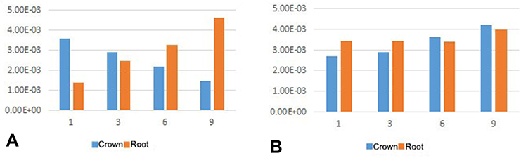 |
Figure 4 Trend of distalization of lateral incisors with different hook heights. (A) Sagittal distalization change; (B) vertical distalization change (Unit: mm). |
Movement Pattern of Canine
When the height of power-arm was 1mm, in the sagittal direction, the crown and root of the canine were moved to the lingual side, and the crown distalization was greater than the root; in the vertical direction, the crown and root distalization were extended, and the crown distalization was less than the root, indicating that the movement of the canine was the slipping movement of the crown and tongue, and clockwise rotation occurred. With the increase of the height of power-arm, in the sagittal direction, the difference between the distalization of the crown and the root of the central incisor continuously decreased. When the height of power-arm increased from 1mm to 3mm, the crown distalization was less than the root displacement. In the vertical direction, the distalization of the root and crown of the tooth continuously decreased, and the decreasing tendency of the crown was less than that of the tooth root. At this time, the canine lip tilted counterclockwise. When the height of power-arm increased from 3mm to 9mm, the difference between the distalization of the root and the tooth continued to decrease, and the canine was more lip tilted, as shown in –Figure 5.
 |
Figure 5 Trend of canine distalization when power-arm height is different. (A) Sagittal distalization change; (B) vertical distalization change (Unit: mm). |
Analysis of Buccal Force Results
The buccal force was applied to obtain the distalization cloud diagram of the upper dentition, as shown in Figure 6.
 |
Figure 6 Cloud diagram of traction on the lip side. |
Distalization Pattern of Central Incisor
Sagittal upward, the central incisor distalization was positive, the crown distalization was less than the root displacement, the crown roots were elongated vertically upward, and the crown distalization was slightly greater than the root, appearing as counterclockwise rotation.
Distalization Pattern of Lateral Incisor
Sagittal upward, the lateral incisor distalization was positive, the crown distalization was less than the root displacement, and the crown roots were elongated vertically upwards, the crown distalization was slightly larger than the root, and it appeared as counterclockwise rotation.
Distalization Pattern of Canine
Sagittal upward, the canine distalization was positive, the crown distalization was greater than the root displacement, and the crown roots were elongated vertically upward, and the crown distalization was greater than the root displacement, appearing as clockwise rotation. See Figure 7.
 |
Figure 7 Trend of upper anterior teeth distalization when traction is on the lip side. (A) Sagittal distalization change; (B) vertical distalization change (Unit: mm). |
Discussion
Compared with labial orthodontics, lingual orthodontics has the advantages of invisibility, beauty, and preserving posterior anchorage.10,11 However, the use of lingual appliance to adduct the anterior teeth easily results in torque loss.12 This adverse effect can be reduced by changing the height of power-arm and the position of the force applied in conjunction with the application of the implant anchorage. Hedayati Z uses the finite element analysis method to analyze the control method of the anterior tooth torque by changing the position of the implant nail. Hedayati believes that the higher the implant screw, the less likely it is to lose the anterior torque.13 Tominaga's research shows that increasing the height of the traction hook and matching the position of the implant nail can achieve root control movement during the retraction of the anterior teeth.14
In this study, a finite element model of lingual orthodontics combined with implanted adduction of upper dentition was established. By changing the height of the extraction, the movement of the upper anterior teeth was analyzed, indicating that increasing the height of power-arm can effectively prevent loss of front teeth torque.
With the increase in the height of the traction hook, the changes in the movement of the upper anterior teeth are not consistent. The canine is more sensitive to changes in the height of power-arm than the central and lateral incisors. But when power-arm height is 9mm, the upper front teeth appear to rotate counterclockwise. This is roughly consistent with the results of previous studies.5,15,16
Some scholars have also conducted research on the position of the traction hook. Through finite element analysis, Feng believes that the traction hook placed in the distal canine is not conducive to the control of the anterior torque and the width of the dental arch. If it is placed between the canine and the lateral incisor It will be better, but also requires additional control.2 This study added applying traction to the labial neck, and found that labial force can better prevent anterior teeth torque loss than lingual force. It is worth noting that the force applied on the labial side of the canine can cause the tongue of the canine to tilt, which can be attributed to the traction being too concentrated on the canine. This phenomenon prompts us to avoid excessive force when adducting the upper dentition as a whole. Meanwhile the use of stiffer archwires makes the traction more evenly distributed.
There are still some limitations in this study. In order to clarify the in-depth mechanism of changes in the movement of the anterior teeth, studying and summarizing the stress distribution and size of periodontal ligament are of great importance, which will be our key research direction in the future.
In summary, during the overall adduction of the upper dentition, the longer the traction hook, the less likely it is to lose the anchorage of the anterior teeth. At the same time, no matter what kind of force is used, a great stress concentration will be formed in the canine area, resulting in the elongation and tongue tilt of the canine. Therefore, it is recommended to use light and harder archwires to control the width between the canines at the same time to avoid the occurrence of the above phenomenon.
Disclosure
The authors report no conflicts of interest in this work.
References
1. Liu DB, Fang ZX, Zhou Y, Huang MF. Three-dimensional finite element study on the tooth movement tendency of the anterior teeth in the overall adduction of traction hooks with different lengths. J Prac Stomat. 2018;34(04):536–539.
2. Feng Y, Kong WD, Cen WJ, et al. Finite element analysis of the effect of power arm locations on tooth movement in extraction space closure with miniscrew Anchorage in customized lingual orthodontic treatment. Am J Orthod Dentofacial Orthop. 2019;156(2):210–219. doi:10.1016/j.ajodo.2018.08.025
3. Jo SY, Bayome M, Park J, Lim HJ, Kook YA, Han SH. Comparison of treatment effects between four premolar extraction and total arch distalization using the modified C-palatal plate. Korean J Orthod. 2018;48(4):224–235. doi:10.4041/kjod.2018.48.4.224
4. Heravi F, Salari S, Tanbakuchi B, et al. Effects of crown-root angle on stress distribution in the maxillary central incisors’ PDL during application of intrusive and retraction forces: a three-dimensional finite element analysis. Prog Orthod. 2013;14:26. doi:10.1186/2196-1042-14-26
5. Aghera D, Shyagali TR, Kambalya P. Evaluation of initial displacement and stresses in the maxillary dentition following en masse retraction using fixed lingual appliance and micro-implants: a finite element analysis. Int Orthod. 2019;17(3):451–460. doi:10.1016/j.ortho.2019.06.005
6. Pol TR, Vandekar M, Patil A, Desai S, Shetty V, Hazarika S. Torque control during intrusion on upper central incisor in labial and lingual bracket system - a 3D finite element study. J Clin Exp Dent. 2018;10(1):e20–e24.
7. Canullo L, Pace F, Coelho P, Sciubba E, Vozza I. The influence of platform switching on the biomechanical aspects of the implant-abutment system. A three dimensional finite element study. Med Oral Patol Oral Cir Bucal. 2011;16:e852–e856. doi:10.4317/medoral.17243
8. Gomez-Gomez SL, Villarraga-Ossa JA, Arcila-Monsalve JC, Moreno-Garzon DM, Ardila CM. Influence of Hyrax screw position on dental movement and cortical bone: a study of finite elements. J Clin Exp Dent. 2019;11(12):e1099–e1108.
9. Park CS, Yu HS, Cha JY, Mo SS, Lee KJ. Effect of archwire stiffness and friction on maxillary posterior segment displacement during anterior segment retraction: a three-dimensional finite element analysis. Korean J Orthod. 2019;49(6):393–403. doi:10.4041/kjod.2019.49.6.393
10. Alobeid A, El-Bialy T, Reimann S, et al. Comparison of the efficacy of tooth alignment among lingual and labial brackets: an in vitro study. Eur J Orthod. 2018;40(6):660–665. doi:10.1093/ejo/cjy005
11. Shyagali TR, Aghera D. Evaluation of stress generation on the cortical bone and the palatal micro-implant complex during the implant-supported en masse retraction in lingual orthodontic technique using the FEM: original research. J Dent Res Dent Clin Dent Prospects. 2019;13(3):192–199. doi:10.15171/joddd.2019.030
12. Alobeid A, El-Bialy T, Khawatmi S, Dirk C, Jäger A, Bourauel C. Comparison of the force levels among labial and lingual self-ligating and conventional brackets in simulated misaligned teeth. Eur J Orthod. 2017;39(4):419–425. doi:10.1093/ejo/cjw082
13. Hedayati Z, Shomali M. Maxillary anterior en masse retraction using different antero-posterior position of mini screw: a 3D finite element study. Prog Orthod. 2016;17(1):31. doi:10.1186/s40510-016-0143-z
14. Tominaga JY, Tanaka M, Koga Y, Gonzales C, Kobayashi M, Yoshida N. Optimal loading conditions for controlled movement of anterior teeth in sliding mechanics. Angle Orthod. 2009;79(6):1102–1107. doi:10.2319/111608-587R.1
15. Mathew RN, Katyal A, Shetty A, Krishna Nayak US. Effect of increasing the vertical intrusive force to obtain torque control in lingual orthodontics: a three-dimensional finite element method study. Indian J Dent Res. 2016;27(2):163–167. doi:10.4103/0970-9290.183120
16. Hakim MAA, Khatab NMA, Mohamed KMG, Elheeny AAH. A comparative three-dimensional finite element study of two space regainers in the mixed dentition stage. Eur J Dent. 2020;14(1):107–114. doi:10.1055/s-0040-1702254
 © 2021 The Author(s). This work is published and licensed by Dove Medical Press Limited. The
full terms of this license are available at https://www.dovepress.com/terms
and incorporate the Creative Commons Attribution
- Non Commercial (unported, 3.0) License.
By accessing the work you hereby accept the Terms. Non-commercial uses of the work are permitted
without any further permission from Dove Medical Press Limited, provided the work is properly
attributed. For permission for commercial use of this work, please see paragraphs 4.2 and 5 of our Terms.
© 2021 The Author(s). This work is published and licensed by Dove Medical Press Limited. The
full terms of this license are available at https://www.dovepress.com/terms
and incorporate the Creative Commons Attribution
- Non Commercial (unported, 3.0) License.
By accessing the work you hereby accept the Terms. Non-commercial uses of the work are permitted
without any further permission from Dove Medical Press Limited, provided the work is properly
attributed. For permission for commercial use of this work, please see paragraphs 4.2 and 5 of our Terms.