Back to Journals » Orthopedic Research and Reviews » Volume 14
A Novel 3D Light Assisted Drawing (3D-LAD) Method to Aid Intraoperative Reproduction of Osteotomy Lines Surrounding a Bone Tumor During Wide Resection: An Experimental Study
Authors He G ![]() , Dai AZ, Mustahsan VM, Blum CL, Kao I, Khan FA
, Dai AZ, Mustahsan VM, Blum CL, Kao I, Khan FA
Received 18 November 2021
Accepted for publication 22 March 2022
Published 8 April 2022 Volume 2022:14 Pages 101—109
DOI https://doi.org/10.2147/ORR.S349240
Checked for plagiarism Yes
Review by Single anonymous peer review
Peer reviewer comments 4
Editor who approved publication: Professor Clark Hung
Guangyu He,1 Amos Z Dai,2 Vamiq M Mustahsan,1 Christopher L Blum,2 Imin Kao,1 Fazel A Khan2
1Department of Mechanical Engineering, Stony Brook University, Stony Brook, NY, USA; 2Department of Orthopedics, Stony Brook University Hospital, Stony Brook, NY, USA
Correspondence: Fazel A Khan, Email [email protected]
Introduction: Computer navigation and customized 3D-printed jigs improve accuracy during bone tumor resection, but such technologies can be bulky, costly, and require intraoperative radiation, or long lead time to be ready in OR.
Methods: We developed a method utilizing a compact, inexpensive, non-X-ray based 3D surface light scanner to provide a visual aid that helps surgeons accurately draw osteotomy lines on the surface of exposed bone to reproduce a well-defined preoperative bone resection plan. We tested the accuracy of the method on 18 sawbones using a distal femur hemimetaphyseal resection model and compared it with a traditional, freehand method.
Results: The method significantly reduces the positional error from 2.53 (± 1.13) mm to 1.04 (± 0.43) mm (p< 0.001), and angular error of the front angle from 2.10° (± 0.83°) to 0.80° (± 0.66°) (p=0.001). The method also reduces the mean maximum deviation of the bone resection, with respect to the preoperative path, from 3.75mm to 2.69mm (p=0.003). However, no increased accuracy was observed at the back side of the bone surface where this method would not be expected to provide information.
Discussion: In summary, we developed a novel 3D-LAD navigation technology. From the experimental study, we demonstrated that the method can improve the ability of surgeons to accurately draw the preoperative osteotomy lines and perform resection of a primary bone sarcoma, with comparison to traditional methods, using 18 sawbones.
Keywords: computer-assist surgery, 3D light assisted drawing, osteotomy lines, structured-light scanning, surgical technique
Introduction
Accurate reproduction of a preoperative plan can be critical in bone tumor surgery, but traditional methods such as free-hand resections are notoriously inaccurate. Standard use of intraoperative intensifier imaging (C-arm) can potentially improve accuracy, but such technology still does not allow for precise identification of the tumor boundaries with respect to anatomic landmarks.1 For these reasons, two technologies - computer navigation2 and customized 3D-printed guides3–5 - have recently been introduced in orthopedic oncology and have been shown to be more accurate than traditional free-hand resections.3,4,6,7 However, each of these technologies still has its drawbacks with respect to actual clinical practice.
Computer navigation systems2 rely on expensive intra-operative hardware and typically require intraoperative registration using either an image-based intraoperative CT scanner (which is bulky, very expensive, and produces substantial intraoperative radiation) or a paired-point registration system. The paired-point registration method requires the surgeon to register one point at a time, which is laborious and ultimately limits accuracy due to a registration process using a relatively small number of data points.8
Customized 3D-printed guides do not require upfront purchase of expensive hardware and are much less bulky than computer navigation systems while still providing high accuracy.5 However, such jigs can have a long fabrication lead time on the order of weeks before they can be ready for use in the operating room (OR).3 Furthermore, each jig can only be used once for a specific case, and then is discarded; over time and the course of multiple surgeries, this can accrue high long-term.
Because of these limitations in existing technologies, we developed an alternative, novel method to improve bone resection accuracy that avoids many of the above mentioned drawbacks. In this method, called the “3D light assisted drawing” (3D-LAD) method, the surgeon uses a standard surgical marking pen to draw an array of “X”s on the bone surface, and a 3D patterned-light scanner captures the topology of bone surface along with the “X” pattern marked on the bone surface. The technology then assists the surgeon in accurately drawing the desired osteotomy lines on the bone surface corresponding to the desired bone tumor resection. In contrast to some of the drawbacks noted above, this method (1) can capture thousands of bone surface points simultaneously for higher registration accuracy9 (rather than a limited number of points captured one-at-A time), (2) uses harmless visible light intraoperatively rather than ionizing X-ray radiation, (3) is compact, (4) uses inexpensive hardware, and (5) uses components that reusable for future cases.
We inquired the following: (1) Does the 3D-LAD method improve the ability of the surgeon to accurately draw the planned osteotomy lines on the bone, before resection, as compared to the traditional methods?; and (2) Does the 3D-LAD method improve the final resection accuracy compared to the traditional methods?
Materials and Methods
Preoperative Planning
Nine pairs of Sawbones® femurs (Pacific Research Laboratories, Inc, Vashon, WA, USA) were imaged by CT scanner (GE VCT, 0.625 mm resolution, 0.5° pitch) to create a DICOM file, from which a 3D surface mesh model was obtained using Geomagic Design X (Geomagic, Inc, Research Triangle Park, NC, USA). In each model, the coronal plane was defined by three points: medial epicondyle, lateral epicondyle, and femoral head center. A distal femur sarcoma was assumed, as illustrated in Figure 1A, because it is the most common site of primary bone tumor.10 A hypothetical joint-sparing hemimetaphyseal resection consisting of three target cutting paths (line segments AB-BC-CD) was then outlined to enclose the distal femur sarcoma. The cutting paths AB-BC-CD were then extended anteriorly and posteriorly to create three target cutting planes that were orthogonal to the coronal plane (Figure 1B).
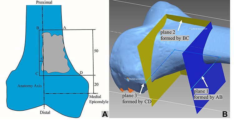 |
Figure 1 Preoperative plan. (A) A schematic to illustrate a distal femur sarcoma enclosed by line segments AB-BC-CD in the coronal plane. (B) Three target resection planes extended anteriorly and posteriorly from AB-BC-CD that were orthogonal to the coronal plane. These are called Plane 1, 2, and 3, as illustrated. |
In conducting experiments for comparison, femur sawbones were marked with the conventional method using anatomic landmarks (conventional group), while the others were marked using the patterned-light scanning method (3D-LAD group). The two groups are presented as follows.
Conventional Group
A standard procedure for wide resection in orthopaedic oncology was performed in the conventional group.11 With the preoperative plan (Figure 1A), the surgeon tried to reproduce the osteotomy lines in reference to known palpable/visible external landmarks on the bone. The surgeon typically uses either the electrocautery or a surgical marking pen to draw on the patient’s femur. After reviewing the plan with careful intraoperative measurements using standard equipment (rigid and flexible rulers), the surgeon drew the three osteotomy lines on the bone using a marking pen to reproduce the preoperative plan (Figure 2).
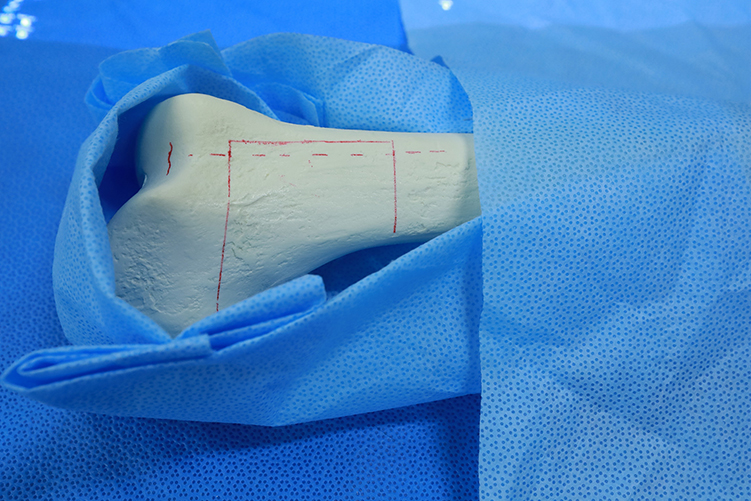 |
Figure 2 The conventional method: A standard procedure for wide resection in orthopaedic oncology in which surgeons tried to reproduce the osteotomy lines in reference to known palpable/visible external landmarks on the bone, and draw the three osteotomy line segments on the bone using a marking pen to reproduce the preoperative plan. |
Patterned-Light Scanning (3D-LAD) Group
The 3D-LAD method starts with the surgeon marking the anterior surface of femur sawbones with rows of “X”s in the region of resection, serving as a reference grid to aid the surgeon to draw the resection planes later. Figure 3A illustrates the limited opened area in an orthopaedic surgery with “X” marks. In our previous study,9 we showed that a 30x30mm2 area of bone surface is sufficient to provide an accurate registration. Next, an EinScan-SP scanner (SHINING 3D Tech. Co., Ltd. Hangzhou, China) was mounted on a tripod and placed 300–400mm above the marked bone surface. Figure 3B illustrated the patterned light projected on the marked area of bone surface.
 |
Figure 3 (A) An illustration of limited exposed area (about 30×30 mm2) of the distal femur, marked with the “X” pattern. (B) A light pattern is projected onto the surface area of the bone marked with the “X” pattern. The distorted light pattern on bone surface is captured by camera. |
Figure 4A shows a scanned bone surface with “X” marks, processed by the Geomagic software to crop out any unnecessary background, leaving only the bony anatomy of the distal femur. We specifically excluded any data points from subchondral areas of bone, since these are covered with cartilage in a real operative setting and would not be able to be adequately visualized in an actual patient. The extracted bone surface in Figure 4A was then registered to the preoperative CT-scan model by a surface matching algorithm, with the surface match shown in Figure 4B. (Refer to our previous article9,12,13 for a detailed explanation of the revised Drost’s algorithm.14) Next, the preoperative plan was superimposed onto the extracted bone surface and shown to the surgeon on a computer as a visual aid to accurately reproduce the preoperative plan by drawing the planned osteotomy lines, as illustrated in Figure 4C. The surgeon was allowed to rotate the virtual plan in three dimensions, as needed, using the grid formed by the rows of X’s as a reference.
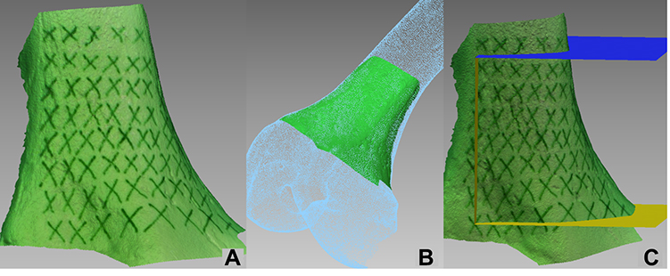 |
Figure 4 (A) An image of scanned surface with the patterned light, marked with “X”. (B) The scanned surface is registered to the CT-scan model by a surface matching algorithm. (C) After the registration is done, the three preoperatively resection planes were superimposed onto the extracted bone surface, in reference to the “X” marks, to serve as a visual aid for the surgeon to accurately reproduce and draw the preoperative plan. |
Evaluate Navigation and Resection Accuracy
After the osteotomy resection line segments AB-BC-CD were marked on femurs by a surgeon, by either the conventional method or the 3D-LAD method, the navigation accuracy is evaluated. This is illustrated in Figure 5. After the resection operation is performed by a surgeon following the osteotomy lines, the resection accuracy is evaluated. Refer to the Appendix for details. Navigation accuracy was presented by the deviation of corners B/C and front angle formed by the line segments AB/BC/CD (Figure 6A). Resection accuracy was measured by the maximum deviation of the osteotomy path (Figure 6B) and the surgical error margin, measured in the Appendix.
 |
Figure 5 Evaluate the navigation accuracy: (A) post-operative surface scanned image is first aligned with reference CT-scan model. After that, the osteotomy lines drawn by a surgeon is compared with the reference CT-scan model in coronal view to assess the navigation accuracy. (B) The result of the 3D-LAD method: the osteotomy lines drawn by a surgeon is in red color (with “X” grid as a visual aid), to compare with the cyan line segments; (C) the result of traditional manual method: the osteotomy lines drawn by a surgeon is in red color, to compare with the cyan line segments. |
 |
Figure 6 Definitions of terminology to measure errors: (A) the “corner deviation” is defined as the displacement error at the corner B or C between the CT-scan reference and the osteotomy lines drawn by a surgeon in the coronal plane, as shown. The “front angle” is the angular displacement of the AB or CD line segment between the CT-scan reference and the best-fit line of the drawn path in the coronal plane, as illustrated with CD line segment in the figure. (B) Many points on the resected bone surface corresponding to line segments AB, BC, and CD are sampled. Each sampled point, as shown, has a distance from the reference preoperative CT-scanned planes extended by AB, BC, CD lines (cf. plane 1, 2 and 3 in Figure 1B), respectively. The “max deviation” is defined as the maximum distance of deviation among all sampled points with a deviation (as shown), with respect to each corresponding plane. The results of maximum deviation are listed in Table A3 in the Appendix. |
Statistical Analysis
The main objective of this paper is to compare the conventional and 3D-LAD methods to evaluate the error of osteotomy. Therefore, only one surgeon conducted the resection procedures for all sawbones in order to produce statistical analysis with significance. Results of the conventional and the 3D-LAD methods were compared using a Student’s t-test. Significance level was set at 0.05.
Results
The experimental results for both navigation and resection accuracy are summarized in Table 1.
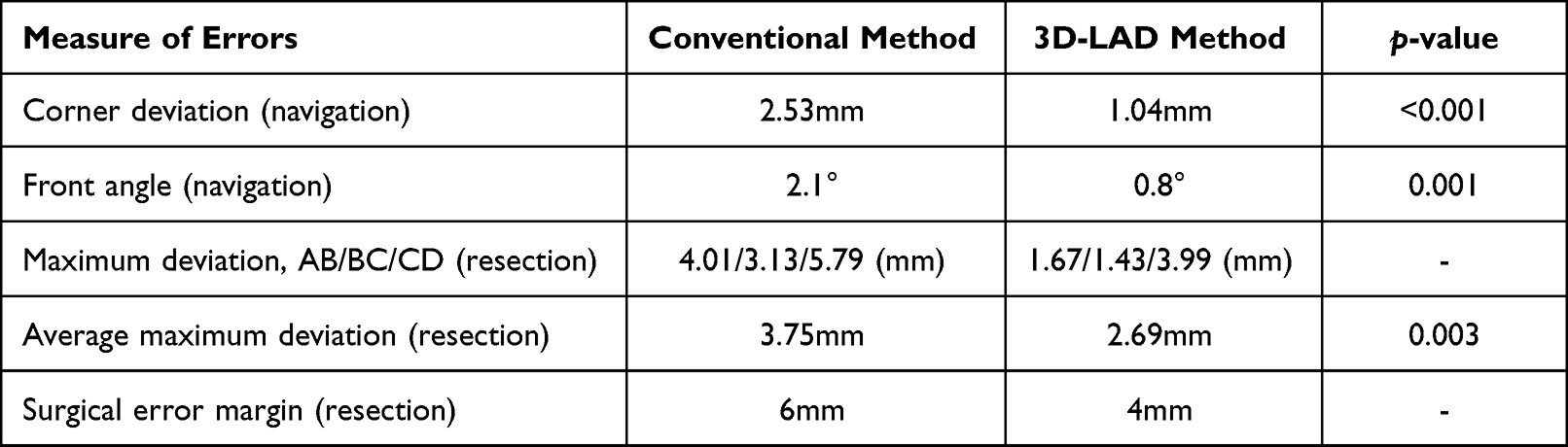 |
Table 1 Summary of Errors Between the Conventional and 3D-LAD Methods for Comparison |
Navigation Accuracy
As defined in the Appendix and illustrated in Figure 6, the navigation accuracy is measured by the “corner deviation” at points B and C, and the “front angle.” The results of statistical analysis of the experimental data are tabulated in Tables A1 and A2 in the Appendix.
The corner variation was 1.04 (±0.43)mm for the 3D-LAD method, compared to 2.53 (±1.13)mm for the conventional method (p<0.001) from Table A1. The average of front angles of AB/BC/CD was 0.80° (±0.66°) for the 3D-LAD method versus 2.10° (±1.83°) for the conventional method (p=0.001) from Table A2. Based on these two analyses, the 3D-LAD method is significantly more accurate than the conventional method in terms of how accurately the surgeon was able to draw osteotomy lines on the bone with respect to the desired preoperative plan.
Resection Accuracy
The resection errors are measured by the “maximum deviation” and “surgical error margin” as defined in the Appendix. From Table A3, the maximum deviations along the AB/BC/CD line segments are 1.67/1.43/3.99 (mm), respectively, for the 3D-LAD method, as compared to 4.01/3.13/5.79 (mm) for the conventional method. The average maximum deviation of the 3D-LAD method was 2.69mm, better than 3.75 mm for the conventional method (p=0.003). It appears that line CD is more prone to deviation. If only AB/BC are considered, the average maximum deviation of the 3D-LAD method was 1.55mm, much better than the 3.57 mm for the conventional method. The “surgical error margin” was 4mm for the 3D-LAD method and 6mm for the conventional method from Table A4. That is, when planning osteotomy path using the 3D-LAD method, only 4mm of error margin needs to be included.
Discussion
In orthopedic oncologic surgery, accuracy of wide-resections is critical to patient survival and functional outcome. Under-resection could lead to local recurrence and increased mortality,15 whereas over-resection could compromise important anatomic structures, such as the articular surface, necessitating more complex, and less durable, reconstructions.7,11 In this study, we demonstrated that the 3D Light Assisted Drawing (3D-LAD) technique - utilizing a 3D scanner with patterned light projection and marking pen drawings on the bone - was more accurate and precise than the conventional method in enabling the surgeon to draw planned resection lines onto the bone. In terms of the actual bone cuts, the 3D-LAD method showed improved accuracy in the near surface of the cut (where the osteotomy lines were drawn), although this accuracy was lost at the back surface (where no osteotomy lines were drawn).
Although there are various tools that have recently been introduced in orthopedic oncology to help the surgeon redraw osteotomy lines on the bone, the 3D-LAD method does have some advantages and disadvantages with respect to these other tools. Standard computer navigation is a recently introduced technology that allows the surgeon to place a probe on the bone and see where the probe is with respect to preoperative imaging; this is an effective tool to help the surgeon reproduce/redraw their preoperative plan on the patient’s bone at the time of surgery.3 However, such technology is very expensive (and therefore only available at some institutions) and requires bulky machinery that must be introduced into the operating room setting. Furthermore, the registration process required for computer navigation also has limitations. For example, the “paired-point” registration technique is commonly used, which can be both laborious and inaccurate since it requires one-by-one point registration for the surgeon in the operating room.16 Alternatively, computer navigation registration can be done via intraoperative CT-type methods,17 but these technologies add even vast more expense, are also very bulky, and require the use of potentially harmful intraoperative X-ray radiation. The 3D-LAD method is based on a light projector-scanner and surgeon drawing with a marking pen, and is therefore comparatively less expensive, smaller, more intuitive, and produces no harmful X-ray radiation, while still maintaining or improving accuracy and less intraoperative labor compared to the paired-point method since it can capture thousands of data points in a single scan.
Customized 3D-printed cutting jigs is another powerful technology that can help the surgeon understand and reproduce their preoperative plan at surgery. In fact, unlike computer navigation or the 3D-LAD method, such technology can serve a dual purpose: just like computer navigation or the 3D-LAD method, it can help the surgeon orient themself to the bone (and therefore in principle redraw the osteotomy lines before cutting, as in this current study), and it can also constrain the saw and allow for an accurate final resection in all planes, which is not done by either the 3D-LAD method or computer navigation. However, customized 3D-printed jigs have a long fabrication time (typically on the order of weeks18). Furthermore, although the individual cost of a jig for one patient is much less than the overall equipment cost for computer navigation, each jig itself can only be used for one case (with reported costs of OR-ready jig around $40,000) and then discarded, which can accrue cumulated costs in the long run. In contrast, the 3D-LAD method uses hardware that is much cheaper than computer navigation/intraoperative CT registration systems, does not require any long fabrication lead time, and can in principle be reused indefinitely.
In this study, there was a notable improvement in the ability of the surgeon to redraw the preoperative osteotomy path on the bone compared to the conventional manual method. Specifically, the 3D-LAD method provides improved resection accuracy at the near surface of the bone cut (where the sawblade cut starts). This does make sense in terms of what the 3D-LAD method actually does – which is to help redraw the osteotomy lines on the near surface of the resection. While the 3D-LAD method offers the surgeon useful information about where to position their sawblade on the bone at the start of the cut, it offers no information to the surgeon about the angle at which the surgeon is supposed to hold the sawblade. Future research can explore methods to control/restrain the angle of the sawblade, as provided by a cutting jig. Our group is currently working on such improvements.
The 3D-LAD method can potentially also be applicable outside the realm of tumor surgery. Accurate reproduction of a preoperative plan is also needed in limb deformity correction. For example, in the setting of distal femur malunion, a precisely performend corrective osteotomy is needed based on the specific patient’s pattern of deformity since an incorrect three-dimensional correction of the distal femur can cause undesirable mechanical axis deviation.19 These patients often receive a CT scan for preoperative planning. In this context, the 3D-LAD method could produce more accurate intraoperative osteotomy lines and consequently improved alignment correction. Furthermore, the 3D-LAD method can be used to increase accuracy of either the resection step or the implant placement step of in megaprosthesis, whether it is used for oncology20 or traumatology.21
This study has several limitations. First, we performed our study on sawbones model in a laboratory setting. This study therefore serves as a proof of concept but might not fully consider some of the variables of the operating room. For example, the 3D-LAD method relies on the surgeon being able to draw clear X’s on bone. In vivo, it is often difficult to draw clear X’s on bone with marker or electrocautery, especially in a most surgical environment. In addition, although all attempts were made to make sure the exposures and visualization required were actually feasible in OR, obstacles such as soft tissues, blood, and surgical retractors could limit the line-of-sight needed for this method. Clearly, further studies in cadavers with soft tissues and ultimately patients are required to truly validate this technique. Second, all the resections in our study were performed by a single third year orthopedic resident. The resection error may have been minimized if resections were performed by a surgeon more experienced with freehand osteotomy cuts, such as a fellowship-trained orthopedic oncologist. Third, when speaking of error on the order of millimeters, the effect of the sawblade kerf, thickness of the cut, cannot be ignored. In our study we used a 1.27mm thick sawblade and the kerf is likely thicker. Fourth, we assumed a completely intra-osseus tumor in our study, such that bone surface could be 3D scanned and registered without issue. For tumors that breach the cortex, the surgeon must expose additional uninvolved bone for accurate registration. Finally, we did not measure the total time required for bone scanning and registration so that it can be compared to registration using the paired-point technique or using intra-operative CT scan.
Although we focused mainly on the experimental study of distal femur model, other anatomic sites and surgical treatment may also benefit from the 3D-LAD method presented in this paper. Further studies with possible modifications of the method can be considered.
Conclusion
In summary, we have developed a novel 3D-LAD technology using 3D scanning technology with visual light pattern. The novel method offers some advantages compared to various existing technologies and is shown to improve the accuracy in reproducing the preoperative plan, based on the results of the experimental study using femur sawbones. We also demonstrated that the 3D-LAD method can effectively assist surgeons to accurately reproduce the preoperative osteotomy resection lines in wide resection of a primary bone sarcoma compared to traditional methods using 18 sawbones. Further study, such as cadaver and clinical experiments, are warranted, as well as extension of the technique to other bones.
Sources of Support
NaviSect (previously was named “Khan Surgical Systems”).
Acknowledgment
We thank Charlie Mazzerese, MS from the Stony Brook University Department of Radiology for their assistance with this project. The first two authors contributed equally to this manuscript, therefore, claim co-first authorship. The last two authors contributed equally to this manuscript, therefore, claim co-senior authorship.
Disclosures
Fazel A. Khan, MD is one of the owners of NaviSect, INC (previously “Khan Surgical Systems, INC”). In addition, Dr. Fazel A Khan has a patent US20200360093A1 pending to Fazel Khan.
Guangyu He, Imin Kao, and Fazel A. Khan have a patent US Patent Application No. 16/854,804 licensed to NaviSect.
Dr Imin Kao reports a patent System and Method to Conduct Bone Surgery pending.
The other authors certify that he or she has no commercial associations (eg, consultancies, stock ownership, equity interest, patent/licensing arrangements, etc.) that might pose a conflict of interest in connection with the submitted article.
References
1. Katz TH, Hasan OH, Miller BJ. Accuracy of X-Ray and magnetic resonance imaging in defining the tumor margin in primary bone sarcoma. Iowa Orthop J. 2021;41(2):27.
2. Cartiaux O, Paul L, Docquier PL, Raucent B, Dombre E, Banse X. Computer-assisted and robot-assisted technologies to improve bone-cutting accuracy when integrated with a freehand process using an oscillating saw. J Bone Joint Surg Am. 2010;92(11):2076–2082. doi:10.2106/JBJS.I.00457
3. Wong KC, Sze KY, Wong IO, Wong CM, Kumta SM. Patient-specific instrument can achieve same accuracy with less resection time than navigation assistance in periacetabular pelvic tumor surgery: a cadaveric study. Int J Comput Assist Radiol Surg. 2016;11(2):307–316. doi:10.1007/s11548-015-1250-x
4. Khan F, Pearle A, Lightcap C, Boland PJ, Healey JH. Haptic robot-assisted surgery improves accuracy of wide resection of bone tumors: a pilot study. Clin Orthop Relat Res. 2013;471(3):851–859. doi:10.1007/s11999-012-2529-7
5. Khan FA, Lipman JD, Pearle AD, Boland PJ, Healey JH. Surgical technique: computer-generated custom jigs improve accuracy of wide resection of bone tumors. Clin Orthop Relat Res. 2013;471(6):2007–2016. doi:10.1007/s11999-012-2769-6
6. Sternheim A, Kashigar A, Daly M, et al. Cone-beam computed tomography-guided navigation in complex osteotomies improves accuracy at all competence levels: a study assessing accuracy and reproducibility of joint-sparing bone cuts. J Bone Joint Surg Am. 2018;100(10):e67. doi:10.2106/jbjs.16.01304
7. Bosma SE, Wong KC, Paul L, Gerbers JG, Jutte PC. A cadaveric comparative study on the surgical accuracy of freehand, computer navigation, and patient-specific instruments in joint-preserving bone tumor resections. Sarcoma. 2018;2018:4065846. doi:10.1155/2018/4065846
8. Aponte-Tinao L, Ritacco LE, Ayerza MA, Muscolo DL, Albergo JI, Farfalli GL. Does intraoperative navigation assistance improve bone tumor resection and allograft reconstruction results? Clin Orthop Relat Res. 2015;473(3):796–804. doi:10.1007/s11999-014-3604-z
9. He G, Mustahsan VM, Bielski MR, Kao I, Khan FA. Report on a novel bone registration method: a rapid, accurate, and radiation-free technique for computer- and robotic-assisted orthopedic surgeries. J Orthopaed. 2021;23:227–232. doi:10.1016/j.jor.2021.01.010
10. Ottaviani G, Jaffe N. The epidemiology of osteosarcoma. Cancer Treat Res. 2009;152:3–13. doi:10.1007/978-1-4419-0284-9_1
11. Avedian RS, Haydon RC, Peabody TD. Multiplanar osteotomy with limited wide margins: a tissue preserving surgical technique for high-grade bone sarcomas. Clin Orthop Relat Res. 2010;468(10):2754–2764. doi:10.1007/s11999-010-1362-0
12. He G, Ricca JM, Dai AZ, et al. A novel bone registration method using impression molding and structured‐light 3D scanning technology. J Orthopaed Res. 2022:1–10. doi:10.1002/jor.25275
13. He G, Dai AZ, Mustahsan VM, et al. A novel method of light projection and modular jigs to improve accuracy in bone sarcoma resection. J Orthopaed Res. 2022:1–15. doi:10.1002/jor.25300
14. Drost B, Ulrich M, Navab N, Ilic S. Model globally, match locally: efficient and robust 3D object recognition. IEEE. 2010;998–1005.
15. Bacci G, Forni C, Longhi A, et al. Local recurrence and local control of non-metastatic osteosarcoma of the extremities: a 27-year experience in a single institution. J Surg Oncol. 2007;96(2):118–123. doi:10.1002/jso.20628
16. Zheng G, Nolte LP. Computer-assisted orthopedic surgery: current state and future perspective. Front Surg. 2015;2:66. doi:10.3389/fsurg.2015.00066
17. Fujiwara T, Kunisada T, Takeda K, et al. Intraoperative O-arm-navigated resection in musculoskeletal tumors. J Orthopaed Sci. 2018;23(6):1045–1050. doi:10.1016/j.jos.2018.06.012
18. Unwin PS, Eshraghi A. Custom Implants. In: Ritacco LE, Milano FE, Chao E, editors. Computer-Assisted Musculoskeletal Surgery: Thinking and Executing in 3D. Springer International Publishing; 2016:181–198.
19. Rollo G, Pichierri P, Grubor P, et al. The challenge of nonunion and malunion in distal femur surgical revision. Med Glas (Zenica). 2019;16(2). doi:10.17392/1016-19
20. Oliva MS, Masci G, Vitiello R, et al. Hip megaprosthesis in oncological surgery: open questions. J Biol Regul Homeost Agents. 2019;33(2Suppl. 1):45–49XIX.
21. Vitiello R, Ziranu A, Oliva MS, et al. The value of megaprostheses in non-oncological fractures in elderly patients: a short-term results. Injury. 2022;53(3):1241–1246. doi:10.1016/j.injury.2021.09.026
 © 2022 The Author(s). This work is published and licensed by Dove Medical Press Limited. The
full terms of this license are available at https://www.dovepress.com/terms
and incorporate the Creative Commons Attribution
- Non Commercial (unported, 3.0) License.
By accessing the work you hereby accept the Terms. Non-commercial uses of the work are permitted
without any further permission from Dove Medical Press Limited, provided the work is properly
attributed. For permission for commercial use of this work, please see paragraphs 4.2 and 5 of our Terms.
© 2022 The Author(s). This work is published and licensed by Dove Medical Press Limited. The
full terms of this license are available at https://www.dovepress.com/terms
and incorporate the Creative Commons Attribution
- Non Commercial (unported, 3.0) License.
By accessing the work you hereby accept the Terms. Non-commercial uses of the work are permitted
without any further permission from Dove Medical Press Limited, provided the work is properly
attributed. For permission for commercial use of this work, please see paragraphs 4.2 and 5 of our Terms.