Back to Journals » Orthopedic Research and Reviews » Volume 13
Trial Tibial Inserts May Result in Different Knee Kinematics from Final Poly Inserts in Total Knee Arthroplasty
Authors Sidhu SP ![]() , Lanting B, Kelly P, Vasarhelyi E
, Lanting B, Kelly P, Vasarhelyi E ![]() , Willing R
, Willing R
Received 12 March 2021
Accepted for publication 17 June 2021
Published 28 June 2021 Volume 2021:13 Pages 81—88
DOI https://doi.org/10.2147/ORR.S309995
Checked for plagiarism Yes
Review by Single anonymous peer review
Peer reviewer comments 2
Editor who approved publication: Professor Clark Hung
Sahil Prabhnoor Sidhu, Brent Lanting, Paul Kelly, Edward Vasarhelyi, Ryan Willing
Western University, Department of Orthopaedic Surgery, London, Ontario, N6A 5A5, Canada
Correspondence: Sahil Prabhnoor Sidhu Email [email protected]
Introduction: Trialling is a key step in total knee arthroplasty (TKA) and helps the surgeon assess for adequate balancing, range of motion, and stability. Despite this, there are no studies investigating knee kinematics when using trial versus final polyethylene tibial inserts.
Materials and Methods: Fourteen fresh frozen cadaveric specimens were cycled in a VIVO joint motion simulator. Using both simple compression and simulated muscle loads, joints were tested after TKA with a trial insert or a final tibial poly insert. Anterior/posterior (AP), internal/external (IE), and varus/valgus (VV) kinematics and laxities were analyzed.
Results: Knees with trial poly inserts had significantly greater AP hysteresis (difference between flexion and extension motion) than those with final poly inserts (p=0.001). There was no significant difference in IE (p=0.563) or VV (p=0.580) hysteresis. There was no difference in AP, IE, or VV motion or laxities when considering the flexion path alone. Prosthetic joints followed different paths in flexion versus extension.
Conclusion: While trial tibial inserts impart valuable information, they may not accurately reproduce the same joint kinematics as final inserts. Balancing of the knee at specific degrees of flexion may depend on the path taken to get there.
Keywords: knee, kinematics, arthroplasty, poly, trial
Introduction
Total knee arthroplasty (TKA) is the gold standard surgical treatment for osteoarthritis of the knee. It is a common procedure and the demand for TKA is increasing rapidly, with a projected increase of 143% in TKAs in the United States by 2050.1 Despite recent advancements however, 10–30% of patients report some degree of dissatisfaction after undergoing TKA.2,3 Thus, there remains room for improvement in this field.
A key step in TKA surgical technique involves the use of trial polyethylene inserts. These are temporary inserts implanted to help the surgeon judge flexion and extension gaps, soft tissue balancing, and motion of the knee, with a variety of thicknesses available. The temporary inserts can be utilized in conjunction with trial or definitive femoral and tibial components. Once inserted, the knee is cycled through its range of motion, with varus/valgus stresses applied. If the temporary insert creates a balanced knee with an appropriate range of motion, the same thickness and size of definitive implant is securely mated to the definitive tibial component. Recently, load sensing tibial trials have also been introduced to assist surgeons in balancing the knee, which has historically been a relatively subjective process.4
Despite a heavy reliance on trial components, we are not aware of any studies investigating whether they provide an accurate representation of TKA motion. Kinematic data are abundant in TKA literature, but do not address how TKA kinematics differ with trial versus final components.5 Kinematics research also tends not to differentiate between the flexion and extension paths of the knee; most papers describe either taking the knee through flexion or extension range of motion, or take an average of the two.5 Important kinematic measures, such as anterior-posterior displacement, may differ between flexion and extension, and this behavior may be influenced by frictional characteristics of the material pairing.
Given this paucity of kinematic data on trial components, we sought to investigate knee kinematics using trial versus definitive polyethylene tibial inserts. We also aimed to identify any differences in flexion and extension paths of the knee.
Materials and Methods
Specimen Preparation
After receiving institutional ethics board approval, fourteen fresh frozen cadaver knees were used to compare joint kinematics after joint replacement using 7 TKAs with trial liners and 7 TKAs with final polyethylene liners.
The cadaveric knee specimens were thawed for 24 hours. They were transected through the mid femur and the mid tibia/fibula approximately 200mm from the epicondylar axis. These specimens were then potted and aligned to be secured to the actuators of the VIVO joint motion simulator (Advanced Mechanical Technology, Inc, Watertown, MA) as previously described and validated.6,7 This involved skeletonizing the proximal 75 mm of the femur and cementing it into a polyvinyl chloride pipe using dental model stone (Modern Materials Golden Denstone Labstone; Modern Materials, Kulzer GmbH, Hanau, Germany). The femur was then mounted in place to the upper actuator control arm. The flexion axis of the femur was defined by flexing and extending the knee and measuring its centre of rotation using an articulated arm coordinate measuring machine (GAGE, FARO Technologies, Lake Mary, FL). Using this technique, once the flexion axis is defined, the femoral position can be adjusted to align the flexion axis of the femur within 2mm of the mechanical flexion axis of the VIVO. The skeletonized portion of the lower leg was then anchored into the lower actuator arm via an acrylonitrile butadiene styrene 5” pipe (100mm long) with the same dental model stone. This potting technique allowed for the best alignment of the joint flexion axis and the mechanical flexion axis of the VIVO. This method ensures the least tibial displacement required to maintain the joint reduced during range of motion testing.
TKA Testing
Each specimen underwent a total knee arthroplasty before the biomechanical analyses described below were carried out. The TKA was performed by a fellowship trained, high volume arthroplasty surgeon using Triathlon components (Stryker Corp., Mahwah, NJ). The triathlon system allows for the use of both Cruciate Retaining (CR) and Condylar Stabilized (CS) inserts (Figure 1). These inserts were either plastic trial components (PPSU (Radel R5500)) that are typically used during bearing thickness determination (7 knees), or real UHMWPE inserts (7 knees). Cadaveric knees were assigned to either trial or real poly inserts in an alternating fashion. Trial components do not feature an anterior locking mechanism that engages with corresponding locking geometry on the tibial tray; therefore, to stabilize trials during testing, poly methyl methacrylate (PMMA) cement (Bosworth Fastray; Keystone Industries GmbH, Singen, Germany) was applied along the anterior surface of the implant. Any excess cement was removed to ensure an unhindered articulation without impingement of the extensor mechanism. Cement was only used to secure the anterior edge of the trial insert and, as such, was easily broken to remove the insert after testing. Each specimen was remounted to its original position on the VIVO with a CR bearing installed. This apparatus was used to perform the biomechanical analyses described below, after which a CS bearing was installed and the process was repeated.
 |
Figure 1 Definitive CR (left) and CS (right) poly inserts. |
Kinematic Testing
Two previously described loading scenarios which simulate passive flexion/extension and laxity testing performed during TKA surgery were used to reduce the joints.6,7 These involved either a 200 N compressive force applied along the long axis of the tibia, or 100 N simulated muscle forces consisting of 50 N of tension on the extensor mechanism (via a pneumatic actuator) and two 25 N hamstring forces generated using the virtual spring force capabilities of the VIVO. Knees were taken through flexion and extension cycles while all remaining degrees of freedom (DoF) were unconstrained (0 N/0 Nm load applied), and the resulting six-DoF kinematics represented the neutral paths of motion of the joints during compression and simulated muscle loading. Displacement sensors built into the machine actuators were used to measure joint kinematics with a precision of 0.1 mm or 0.1 degrees.8 Then, AP forces, IE moments, and VV moments were superimposed over both loading scenarios. The resulting kinematics defined the anterior, posterior, internal, external, varus, and valgus limits of motion, respectfully, which were later used to calculate AP, IE, and VV laxities. Positive values represented anterior displacement of the tibia relative to the femur for AP motion, external rotation of the tibia with respective to the femur for IE motion, and valgus for VV motion. When a 200 N compressive force was used to reduce the joint, the superimposed loads were a ± 60 N AP force, a +/ 2 Nm IE moment, and a ± 5 Nm VV moment. For simulated muscle scenarios, the superimposed loads were proportionally reduced to a ± 30 N AP force, a ± 1 Nm IE moment, and a ± 2.5 Nm VV moment. These loads were determined during pilot testing and were chosen based on their ability to displace the joints to laxity limits without exceeding range of motion limits of the simulator.
Motions were repeated for four flexion/extension cycles (25 s period for each) and recorded during the final cycle using a 100-Hz sampling rate (2500 samples/cycle) in all cases. Six-DoF kinematics data were recorded by the simulator using Grood and Suntay coordinate conventions.9 This assumed perfect alignment of the anatomical coordinates of the specimen with the mechanical axes of the apparatus. Later, this was corrected based on anatomic coordinate systems identified on CT reconstructions of the femur and tibia which were co-registering to their actual positions on the VIVO. All kinematics data were smoothed using a zero-offset low-pass fourth order Butterworth filter (fc = 1-Hz), and subsequently down-sampled to 200 samples per full flexion/extension cycle using a spline interpolation function (interp1) in Matlab (The MathWorks, Natick, MA, USA). Laxities in the AP, IE and VV directions throughout the entire flexion motion were calculated as the difference in the corresponding limits of motion.
A primary outcome measure of this study was the hysteresis, or difference between the flexion and extension motions. The concept of hysteresis is illustrated in Figure 2, which shows an example of the different paths followed by prosthetic knees in flexion versus extension. These were measured for AP, IE, and VV kinematics. Secondary measures were the AP translation, IE rotation, VV motion, and laxities collected from the flexion phase of the motion studies only.
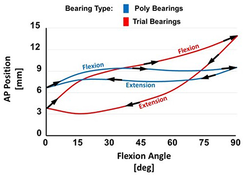 |
Figure 2 An illustration of hysteresis, which is the difference between the paths followed by the knee in flexion versus extension. The example shown includes flexion and extension paths for trial (red) and final (blue) tibial inserts. |
Isolated Prosthesis Testing
We then tested isolated Stryker Triathlon knee system prosthesis components directly mounted on the VIVO. The femoral component was mounted to the upper actuator arm via a mounting pin that allowed for the flexion axis of the femoral component to be aligned parallel with the flexion axis of the VIVO machine. The femoral component was mounted to the mounting pin with PMMA cement (Bosworth Fastray; Keystone Industries GmbH, Singen, Germany). The tibial component was attached to the lower actuator via a mounting platform. The tibial baseplate component was anchored into place using dental model stone (Modern Materials Golden Denstone Labstone; Modern Materials, Kulzer GmbH, Hanau, Germany). This allowed for easy interchangeability of the tibial articulating component. For assessment of 0–90 degrees of flexion/extension we used the CR components starting with mounting the CR trial. Again, the same kinematic data was recorded as previously mentioned for cyclical flexion and extension at 100Hz. Testing was performed with 200N of compression combined with virtual ligaments to simulate joint motion most comparable to the intact knee joint. Simple point-to-point ligaments were applied on the vivo machine to simulate the presence of collateral ligaments. These virtual ligaments have properties acting as a non-linear springs connecting the femur to the tibia.10,11 The stiffness and reference strain for the ligaments was set such that they were tight in extension and loose in flexion, based on virtual ligaments employed in a previous study.12 This equated to approximately 150N in extension and 50N in flexion. We used the trial and final tibial polys separately to run cyclical 0–90 degree flexion testing and obtain kinematic data.
Data Analysis
Kinematics and laxity data were further sub-sampled using 15-degree increments from 0 to 90 degrees of flexion for statistical analysis. Three-way mixed analyses of variance (ANOVAs) were performed using SPSS (IBM Corp., Armonk, NY, USA) with joint reduction method (200N compressive force versus simulated muscle forces) and insert geometry (CR versus CS) as within-subject repeated-measures independent variables and bearing material (trial versus real poly) as a between-subject independent variable. Separate ANOVAs were performed for each kinematic and laxity outcome measure separately as the dependent variable. Hysteresis was calculated by taking the difference between flexion and extension values at 15, 30, 45, 60, and 75 degrees and then taking the average. Statistically significant differences were reported when P < 0.05 after a Greenhouse–Geisser correction. When significant effects were identified, differences in means were reported with 95% confidence intervals (CIs), if significant after a Bonferroni correction for repeated comparisons.
Results
There was no significant difference in “neutral” kinematics (flexion paths) between trial and final poly inserts, in terms of the AP displacements (p=0.108), IE rotations (p=0.821) and VV angulations (p=0.294). These results are illustrated in Figure 3. Although there were no differences in the kinematics based on the flexion path, there was a significant difference in AP hysteresis (the difference between flexion and extension paths) between trial and final poly inserts (p=0.001). Again, the concept of hysteresis is illustrated in Figure 2, which maps an example of the different paths followed by prosthetic knees in flexion versus extension. This difference was present regardless of whether CR versus CS inserts, or simple compression versus simulated muscle forces were used. There was, however, no difference in IE hysteresis (p=0.563) or VV hysteresis (p=0.580) between trial and definitive poly. This hysteresis data is illustrated in Figure 4. AP hysteresis, or flexion/extension path mismatch, was larger with the use of trial inserts, as opposed to final poly inserts, as shown in Figure 4. P-values are summarized in Table 1.
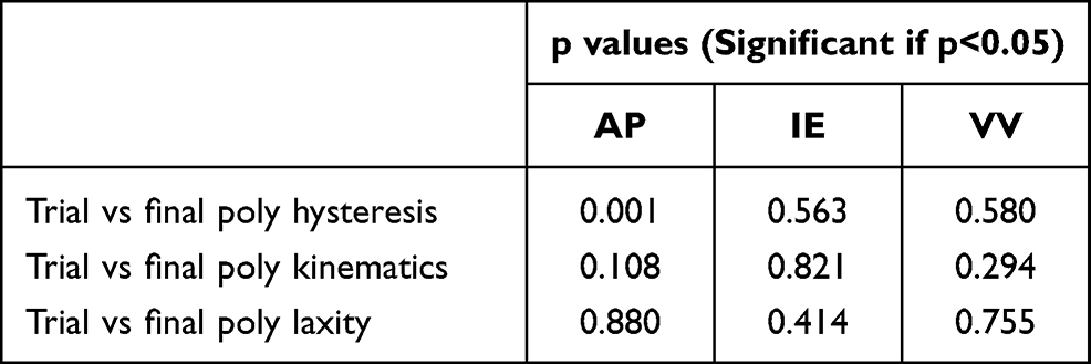 |
Table 1 p values for Hysteresis, Kinematics, and Laxity Analysis When Comparing Trial versus Final Poly Inserts |
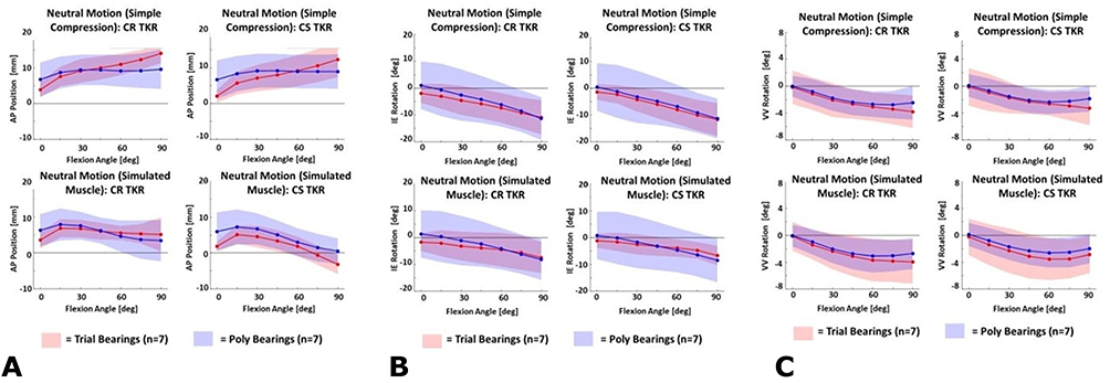 |
Figure 3 (A–C) Average “neutral” AP (A), IE (B), and VV (C) kinematics during 0–90 degree flexion cycles under simple compression and simulated muscle conditions. Performed with CR TKAs and CS TKAs for both trial and final poly inserts. |
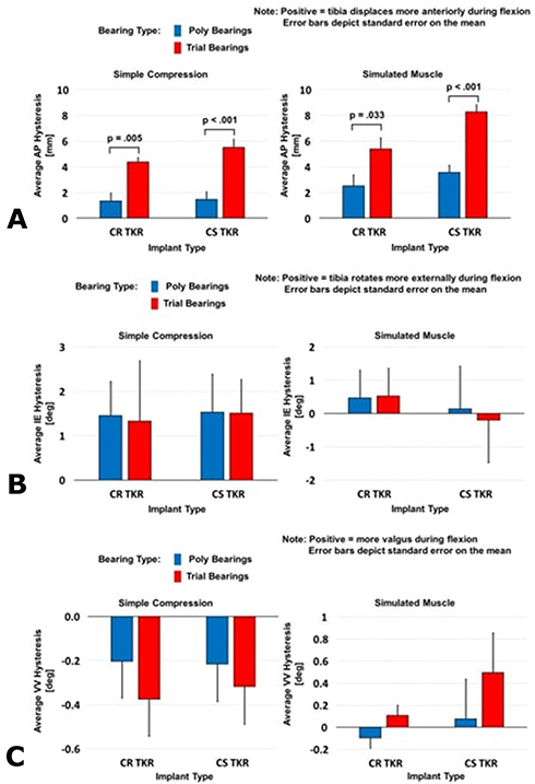 |
Figure 4 (A–C) AP (A), IE (B), and VV (C) hysteresis during 0–90 degree flexion and extension cycles under simple compression and simulated muscle conditions. Performed with CR TKA and CS TKA for both trial (red) and final (blue) tibial inserts. |
There was no significant difference in laxities between trial and final poly inserts, regardless of whether CR versus CS, or simple compression versus simulated muscle forces were used. There was no significant difference in AP laxity (p=0.880), IE laxity (p=0.414), or VV laxity (p=0.755). Laxity data is shown in Figure 5.
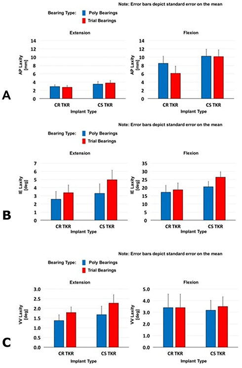 |
Figure 5 (A–C) AP (A), IE (B), and VV (C) laxity during 0–90 degree flexion and extension cycles under simple compression and simulated muscle conditions. Performed using CR TKAs and CS TKAs for both trial (red) and final (blue) tibial inserts. |
Finally, when looking at isolated TKA components simulated on the VIVO, we focused on AP hysteresis. The results of this are illustrated in Figure 6. When both 200 N of compression and virtual ligaments were used (most accurate representation of knee), the trial insert resulted in greater AP hysteresis than the final poly. This was similar to the results of the cadaveric models described above.
 |
Figure 6 AP hysteresis testing of isolated implants during 0–90 degree flexion and extension cycles on the VIVO with CR trial and final poly tibial inserts. A combination of compression and virtual ligaments was used. |
Discussion
Soft tissue balancing is a key step in TKA, with soft tissue imbalance being responsible for up to 35% of early revisions in the United States.4,13 The use of trial components, including trial tibial inserts, is important in balancing the knee. Surgeons rely heavily on these temporary components to help assess for adequate range of motion, stability, and balancing.4 They assume that these trial components provide an accurate representation of what knee kinematics will be like after insertion of the final implants. However, no literature exists investigating knee kinematics with trial versus definitive poly inserts.
Our study interestingly found that indeed kinematics may differ between trial and final polyethylene tibial inserts. In particular, AP hysteresis, or the difference between the path followed by the knee in flexion and extension, differed significantly between the two (p=0.001). AP hysteresis was significantly greater with the trial tibial inserts as compared to the definitive polyethylene implant. This indicates a greater degree of mismatch between the path followed by the knee in flexion versus extension with a trial insert. Perhaps this could also be interpreted as an increased “stickiness” of the trial component. The coefficient of friction during interaction of the trial insert with the femoral/tibial components could contribute to it producing less of a smooth gliding motion and encouraging a rolling motion. This difference in hysteresis could have interesting implications; in particular it would mean that surgeons need to take care when trusting intraoperative knee kinematics when using trial implants. Although trial inserts are likely reliable tools for assessing the terminal range of motion and varus/valgus laxity, which is what most surgeons utilize them for, they do not exactly recreate the same AP motion as final inserts when assessing both the flexion and extension paths of the knee. Hysteresis may also have implications in the balancing of CR knees, where the knee is considered to be too tight if femoral rollback is noted to be excessive. Cycling the knee after implantation of final components and confirming adequacy of balancing is essential.
Our results found no difference, however, in IE (p=0.563) and VV (p=0.580) hysteresis between trial and final tibial inserts. This may indicate that trial tibial inserts are still reliable tools with respect to judging IE and VV motion of the final knee. Interestingly, there were no statistically significant differences in AP motion when only data from the flexion path was considered. This could be due to high variability between specimens and a relatively small effect; however, the effect of materials on AP kinematics was doubled when measuring hysteresis which increased the likelihood of detecting differences.
A significant finding of our study was that the AP path of prosthetic knees differed in flexion and extension (Figure 2). As opposed to the gliding motion of a native knee, prosthetic knees had greater friction and followed more of a rolling motion. The femur was noted to push the tibia more anterior in flexion and pull the tibia posterior in extension. The implications of this could be very interesting; as odd as it may seem, perhaps the balancing of the knee in specific positions could differ depending on the path taken to get there. Furthermore, for future biomechanical studies on TKA, it may be prudent to analyze both the flexion and extension paths, instead of just one or taking an average of the two.
The findings of this study may also have implications for the use of load-sensing, or “smart”, tibial inserts. These devices provide an objective, dynamic tool to assist in balancing of the knee and contact kinematics via an estimate of the centre of pressure within either condyle.4 Although results with these devices have been promising, with some studies even showing improved patient outcomes, our kinematic data may mean that they are not perfect;4,14 depending on friction, the measured contact kinematics during flexion and extension may differ from that of the final poly due to differing hysteresis.
Our study did have some notable limitations. It was a cadaveric biomechanical study and, as such, may not perfectly replicate in vivo kinematics. Furthermore, sample size was small, and specimens received either a trial insert or definitive polyethylene insert; but were not tested with both which prevents direct comparison. The isolated implant testing, however, provided a direct comparison of the effects of bearing materials. It should also be noted that our findings represented passive, intraoperative flexion/extension motions. Ultimately, further kinematics studies are required to investigate knee motion with trial versus final TKA components.
Conclusion
Trial and final polyethylene tibial inserts may result in different knee kinematics. In particular, trial tibial inserts resulted in greater AP hysteresis as compared to final poly inserts. There was no significant difference in IE and VV motion between the two. The path of prosthetic knees also differed in flexion versus extension. Surgeons should take care when using trial components.
Consent Statement
This study was granted Institutional Review Board (IRB) (Western/Lawson Research Ethics Board) approval, which is available upon request.
Disclosure
Dr Brent Lanting reports grants, personal fees for institutional support from Smith and Nephew, Stryker, DePuy, and Zimmer, owns stocks from IdealFit Spacer Solutions, during the conduct of the study. Dr Edward Vasarhelyi reports grants, personal fees, non-financial support for institutional and research support from DePuy, Zimmer Biomet, Stryker, Smith and Nephew, and Hip Innovation Technology, outside the submitted work. The authors report no other conflicts of interest in this work.
References
1. Inacio MCS, Paxton EW, Graves SE, Namba RS, Nemes S. Projected increase in total knee arthroplasty in the United States - an alternative projection model. Osteoarthritis Cartilage. 2017;25(11):1797–1803. doi:10.1016/j.joca.2017.07.022
2. Bourne RB, Chesworth BM, Davis AM, Mahomed NN, Charron KDJ. Patient satisfaction after total knee arthroplasty: who is satisfied and who is not? Clin Orthop. 2010;468(1):57–63. doi:10.1007/s11999-009-1119-9
3. Van Onsem S, Verstraete M, Van Eenoo W, Van Der Straeten C, Victor J. Are TKA kinematics during closed kinetic chain exercises associated with patient-reported outcomes? A preliminary analysis. Clin Orthop Relat Res. 2019;17.
4. Risitano S, Karamian B, Indelli PF. Intraoperative load-sensing drives the level of constraint in primary total knee arthroplasty: surgical technique and review of the literature. J Clin Orthop Trauma. 2017;8(3):265–269. doi:10.1016/j.jcot.2017.06.004
5. Angerame MR, Holst DC, Jennings JM, Komistek RD, Dennis DA. Total knee arthroplasty kinematics. J Arthroplasty. 2019;34(10):2502–2510. doi:10.1016/j.arth.2019.05.037
6. Sidhu SP, Moslemian A, Yamomo G, et al. Lateral subvastus lateralis versus medial parapatellar approach for total knee arthroplasty: a cadaveric biomechanical study. Knee. 2020;27(6):1735–1745. doi:10.1016/j.knee.2020.09.022
7. Willing R, Moslemian A, Yamomo G, Wood T, Howard J, Lanting B. Condylar-stabilized TKR may not fully compensate for PCL-deficiency: an in vitro cadaver study. J Orthop Res. 2019;37(10):2172–2181. doi:10.1002/jor.24392
8. Advanced Mechanical Technology, Inc. VIVOTM, bringing new life to joint motion simulation. AMTI; 2013. https://www.amti.jp/AMTI-VIVO-Brochure-Rev2-HiRes.pdf.
9. Grood ES, Suntay WJ. A joint coordinate system for the clinical description of three-dimensional motions: application to the knee. J Biomech Eng. 1983;105(2):136–144. doi:10.1115/1.3138397
10. Blankevoort L, Huiskes R. Ligament-bone interaction in a three-dimensional model of the knee. J Biomech Eng. 1991;113(3):263–269. doi:10.1115/1.2894883
11. Bloemker KH, Guess TM, Maletsky L, Dodd K. Computational knee ligament modeling using experimentally determined zero-load lengths. Open Biomed Eng J. 2012;6:33–41. doi:10.2174/1874120701206010033
12. Willing R, Walker PS. Measuring the sensitivity of total knee replacement kinematics and laxity to soft tissue imbalances. J Biomech. 2018;77:62–68. doi:10.1016/j.jbiomech.2018.06.019
13. Sharkey PF, Hozack WJ, Rothman RH, Shastri S, Jacoby SM, Insall Award paper. Why are total knee arthroplasties failing today? Clin Orthop. 2002;404:7–13. doi:10.1097/00003086-200211000-00003
14. Chow JC, Breslauer L. The use of intraoperative sensors significantly increases the patient-reported rate of improvement in primary total knee arthroplasty. Orthopedics. 2017;40(4):e648–51. doi:10.3928/01477447-20170503-01
 © 2021 The Author(s). This work is published and licensed by Dove Medical Press Limited. The
full terms of this license are available at https://www.dovepress.com/terms
and incorporate the Creative Commons Attribution
- Non Commercial (unported, 3.0) License.
By accessing the work you hereby accept the Terms. Non-commercial uses of the work are permitted
without any further permission from Dove Medical Press Limited, provided the work is properly
attributed. For permission for commercial use of this work, please see paragraphs 4.2 and 5 of our Terms.
© 2021 The Author(s). This work is published and licensed by Dove Medical Press Limited. The
full terms of this license are available at https://www.dovepress.com/terms
and incorporate the Creative Commons Attribution
- Non Commercial (unported, 3.0) License.
By accessing the work you hereby accept the Terms. Non-commercial uses of the work are permitted
without any further permission from Dove Medical Press Limited, provided the work is properly
attributed. For permission for commercial use of this work, please see paragraphs 4.2 and 5 of our Terms.