")
Back to Archived Journals » Robotic Surgery: Research and Reviews » Volume 4
Tip design for safety of steerable needles for robot-controlled brain insertion
Authors Lehocky CA, Fellows-Mayle W, Engh JA, Riviere CN
Received 4 May 2017
Accepted for publication 26 September 2017
Published 26 October 2017 Volume 2017:4 Pages 107—114
DOI https://doi.org/10.2147/RSRR.S141085
Checked for plagiarism Yes
Review by Single anonymous peer review
Peer reviewer comments 4
Editor who approved publication: Professor Terry Lairmore
Craig A Lehocky,1 Wendy Fellows-Mayle,2 Johnathan A Engh,2 Cameron N Riviere3
1Department of Biomedical Engineering, Carnegie Mellon University, Pittsburgh, PA, USA; 2Department of Neurological Surgery, University of Pittsburgh Medical Center, Pittsburgh, PA, USA; 3The Robotics Institute, Carnegie Mellon University, Pittsburgh, PA, USA
Background: Current practice in neurosurgical needle insertion is limited by the straight trajectories inherent in rigid probes. One technique allowing curvilinear trajectories involves flexible bevel-tipped needles, which bend during insertion because of their asymmetry. In the brain, safety will require avoidance of the sharp tips often used in laboratory studies, in favor of a more rounded profile. Steering performance, on the other hand, requires maximal asymmetry. Design of safe bevel-tipped brain needles, thus, involves management of this trade-off by adjusting needle gage, bevel angle, and fillet (or tip) radius to arrive at a design that is suitably asymmetrical while producing strain, strain rate, and stress below the levels that would damage brain tissue.
Methods: Designs with a variety of values of needle radius, bevel angle, and fillet radius were evaluated in finite-element simulations of simultaneous insertion and rotation. Brain tissue was modeled as a hyperelastic, linear viscoelastic material. Based on the literature available, safety thresholds of 0.19 strain, 10 s-1 strain rate, and 120 kPa stress were used. Safe values of needle radius, bevel angle, and fillet radius were selected, along with an appropriate velocity envelope for safe operation. The resulting needle was fabricated and compared with a Sedan side-cutting brain biopsy needle in a study in the porcine model in vivo (N=3).
Results: The prototype needle selected was 1.66 mm in diameter, with a bevel angle of 10° and a fillet radius of 0.25 mm. Upon examination of postoperative computed tomography and histological images, no differences in tissue trauma or hemorrhage were noted between the prototype needle and the Sedan needle.
Conclusion: The study indicates a general design technique for safe bevel-tipped brain needles based on the comparison with relevant damage thresholds for strain, strain rate, and stress. The full potential of the technique awaits the determination of more exact safety thresholds.
Keywords: robotic surgery, needle steering, bevel-tipped needle, stress, strain, strain rate, finite-element analysis
Introduction
Focally defined diseases of the brain such as cancer, infection, and neurodegenerative disorders often impart significant physical, motor, sensory, and cognitive disability. Although brain cancer is not among the most common forms of cancer, it is a particularly lethal cancer. Nearly 14,000 people die each year from primary brain cancers alone, and it is the second most common form of cancer death in young patients.1 Treatment options for these disorders that frequently occur in focal, anatomically defined regions are limited because of several factors. The lesions are often difficult to reach through surgical means because of the delicate nature of the surrounding brain tissue and the confined environment of the skull. Systemically delivered therapeutics face the challenge of crossing the blood–brain barrier.2 When medications or radiation therapy do enter the central nervous system, the challenge remains for these medications to target the pathology while not harming healthy brain tissue, as chemotherapeutics delivered to the brain and intracranial radiation can potentially induce cognitive changes.3,4
Deep insertion is common in brain biopsy5 and is increasingly being employed for deep brain stimulation6 and experimental therapies such as the direct delivery of therapeutics to tumors.7–9 One such method of delivery involves multiple injections of therapeutics to cover the three-dimensional boundaries of the lesion under image guidance.10,11 This procedure is limited by straight trajectories that rigid needles must follow, as each injection at a new location requires the full removal of the needle and reinsertion at a new location on the cortical surface. Multiple rigid needle insertions can increase the risk of damaging critical anatomy or vasculature situated between the insertion point on the cortical surface and the target, and can increase the risk of infection. To circumvent these issues, many groups have begun developing methods to robotically steer needles along curvilinear paths through tissue.12–15 Some of these techniques are active methods that involve external forces to steer the probe tip, such as systems of multiple precurved concentric tubes16 and systems of external magnets for guidance of a metallic tip.17 Others are passive methods that rely for steering on the interaction between the tissue and an asymmetrical tip, such as bevel-tipped needles18,19 (Figures 1 and 2) and certain other probes of more complex geometry, such as a bioinspired one based on a wasp ovipositor.13,15,20 In laboratory studies ex vivo, beveled needles with sharp tips are often used;21,22 however, this is obviously not compatible with clinical neurosurgery. The primary challenge in designing beveled needle tips for use in clinical applications is that the goal of maximizing asymmetry in order to preserve steering behavior presents a trade-off with the goal of maximizing bluntness for the sake of safety.
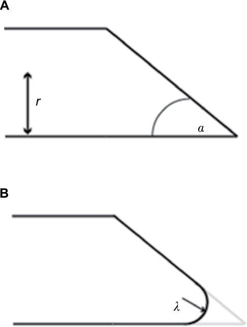 | Figure 1 Bevel-tipped needle design parameters. Notes: (A) A sharp bevel-tipped needle profile, with bevel angle α and needle radius r. (B) A rounded-tip (or filleted) bevel-tipped needle, with fillet radius λ. Simulations in this study were conducted at a variety of values of fillet radius, bevel angle, and needle radius, as indicated in Table 1. |
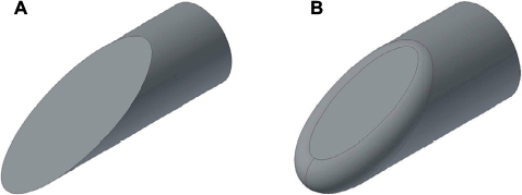 | Figure 2 Examples of computer-aided designs of beveled needle tips, with and without a fillet. Notes: (A) Sharp (λ=0) needle tip with needle radius r=0.83 mm and bevel angle α=20°. (B) Filleted needle tip with needle radius r=0.83 mm, bevel angle α=20°, and fillet radius λ=0.25 mm. |
This paper describes initial efforts toward the design of a bevel-tipped steerable needle tip and the corresponding velocity envelope that will preserve the safety of brain tissue during insertion. Simulated insertions of needles utilizing a variety of design parameters are performed in order to select an appropriate design for safety. These simulations are followed by preliminary safety testing of the resulting needle tip prototype in the porcine model in vivo, in comparison with a standard Sedan side-cutting biopsy needle.
Needle design and simulation
Safety thresholds for instrument insertion in brain
Literature quantifying thresholds for brain injury due to surgical instrument insertion into the brain is generally unavailable, and the research needed to establish such thresholds is beyond the scope and resources of the current project. Therefore, lacking such information for the time being, in order to obtain initial estimates, it is necessary to turn to other situations or scenarios, such as traumatic brain injury studies. There are several studies in vivo that have quantified damage thresholds to brain tissue in terms of strain and strain rate. Morrison et al suggested tolerance criteria of between 0.1 and 0.5 strain, at strain rates between 10 and 50 s-1.20 Conservative estimates of damage thresholds for white matter are Lagrangian strain of 0.14 for morphological injury and 0.13 for electrophysiological injury.21 Shreiber et al proposed an injury criterion of 0.19 logarithmic strain.22 Based on these references, for this project we adopted safety thresholds of 0.19 for strain and 10 s-1 for strain rate.
The available literature generally quantifies damage thresholds to brain tissue in terms of strain and strain rate, not stress. However, studies quantifying damage thresholds in terms of stress do exist for some tissues, from which at least an admittedly rough but practical criterion for preliminary use may be gleaned. Experiments in porcine liver in vivo yielded a significantly elevated number of apoptotic cells at 180 and 240 kPa, but not at 60 or 120 kPa; in other words, 120 kPa was the highest tested stress value that was found to be safe. 26 Based on these data, in the absence of a more relevant reference with regard to brain tissue, we adopted a stress limit of 120 kPa for safety for the purpose of this preliminary investigation.
Needle insertion modeling
Miller and Chinzei27 developed a nonlinear viscoelastic constitutive brain tissue model that replicated brain behavior at low strain rates consistent with neurosurgical procedures. Shortly thereafter, Miller28 linearized the model to make the implementation of such a model more feasible for finite-element modeling. The model includes hyperelastic material properties that capture the instantaneous behavior of brain tissue, as well as linear viscoelastic properties that capture the time-dependent properties of the tissue. We implemented this model in ABAQUS software (Dassault Systèmes, Vélizy-Villacoublay, France) with the constitutive coefficients identified by Miller.28 The size of the tissue block was increased, and results for stress, strain, and strain rate were monitored until the effects of boundary conditions on tissue responses were stabilized; this determined the size of the final tissue block used, which was 12×12×12 mm. Quadratic tetrahedral elements (C3D10H in ABAQUS software, for incompressible materials) were used. Mesh density varied from 2 mm in outer tissue to 0.4 mm in the central 3×3-mm square prismatic region near the needle, based on the results of preliminary studies. Node density was greater surrounding the region of the needle tip than at the boundaries of the tissue, in order to maximize the sensitivity of results while minimizing computation time. All simulations began with the needle already inserted and fully surrounded by tissue. Contact was specified between the needle and the tissue through the general contact algorithm. Friction was modeled between the needle tip and tissue surfaces through the penalty contact algorithm, with a coefficient of friction μ=0.5.29
Finite-element models of bevel-tipped needles with various values of design parameters (radius r, bevel angle α, and bevel-tip fillet radius λ) were created and tested. The needle parameter values tested are shown in Table 1. Figure 3 shows the stress results for all needles from insertion of 0.1 mm (at 1 mm/s) while being rotated 180° (at 180°/s). Figure 4 shows the corresponding results for strain. It may be noted that the green line with “×” markers represents the needle radius of 1.25 mm and the fillet radius of 1.25 mm (i.e., a hemispherical tip), which matches the geometry of the Sedan side-cutting biopsy needle. All needle designs remained below the safety threshold for stress, but only some remained below the threshold for strain. Based on these results, the set of parameters chosen for the prototype needle comprised a radius of 0.83 mm (i.e., 5 Fr), a bevel angle of 10o, and a fillet radius of 0.25 mm.
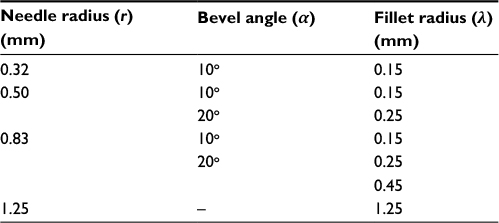 | Table 1 Set of needle design parameters used in simulations |
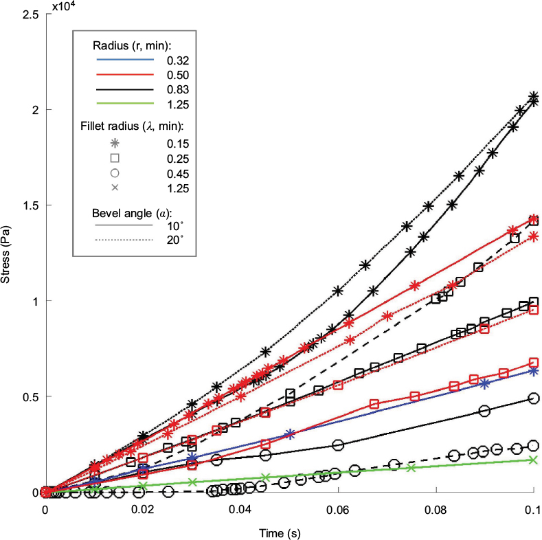 | Figure 3 Stress for all simulations in the hyperelastic–viscoelastic three-dimensional finite-element model. Notes: All needles remained under the stress threshold for safety in brain tissue. Note that the green line with “×” markers matches the geometry of the Sedan side-cutting biopsy needle. |
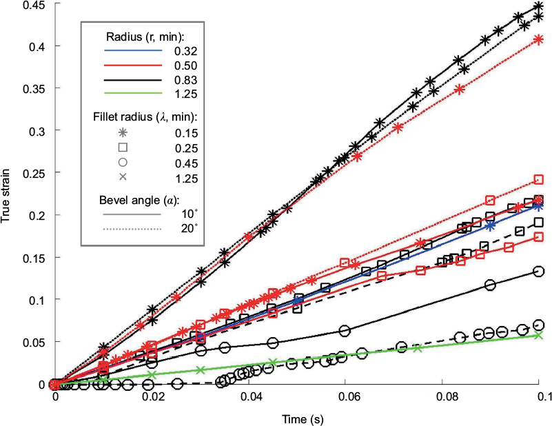 | Figure 4 True strain for all simulations in the hyperelastic–viscoelastic three-dimensional finite-element model. Notes: Only certain combinations of needle parameters remained below the strain safety threshold for brain tissue. Note that the green line with “×” markers matches the geometry of the Sedan side-cutting biopsy needle. |
The effect of control inputs on the strain rate was studied in simulation by varying the translational and rotational speeds for the 0.83 mm radius, 10o bevel angle, and 0.25 mm fillet radius needle. The velocity conditions were “slow” (0.5 mm/s and 90°/s), “medium” (1 mm/s and 180°/s), and “fast” (2 mm/s and 360°/s). Figure 5 shows the effect of input velocities on the strain rate. To keep the strain rate dependably below the stated threshold of 10 s-1, the medium speed of translation (1 mm/s) was selected for use in the experimentation phase, based on the data of Figure 5, and because it is comparable to speeds considered safe for blunt needles in previous studies.30
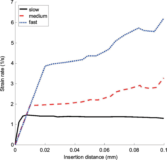 | Figure 5 Tissue strain rates as a function of slow (0.5 mm/s and 90°/s), medium (1 mm/s and 180°/s), and fast (2 mm/s and 360°/s) simultaneous insertion and rotation of the prototype bevel-tipped needle (5 Fr, bevel angle 10°, fillet radius 0.25 mm) in the hyperelastic–viscoelastic finite element model. |
Experimentation in porcine model in vivo
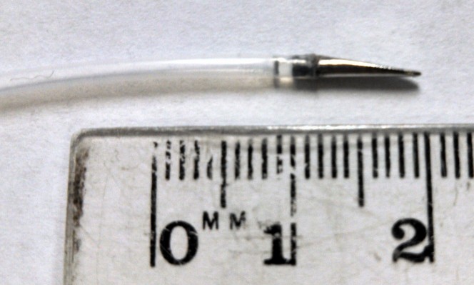
A prototype needle tip with the parameters determined above (5 Fr, bevel angle 10°, fillet radius 0.25 mm) was fabricated (Proto Labs, Inc., Maple Plain, MN, USA) for testing and affixed to polytetrafluoroethylene tubing of equal outer diameter (Figure 6). An experiment in the porcine model in vivo was performed under a protocol approved by the Institutional Animal Care and Use Committee of the University of Pittsburgh, in conformity with the Guide for the Care and Use of Laboratory Animals.31 Three large (30–45 kg) crossbred male swine were used. Each subject was intubated via single-lumen endotracheal intubation prior to administration of anesthesia (isoflurane 1%–3%). Artificial ventilation was utilized to maintain the rate of respiration between 12 and 16 breaths per minute. The underbelly was shaved and cleaned in order for placement of electrocardiography leads. Electrocardiogram status and oxygen saturation were monitored throughout the entire experiment.
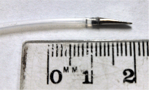 | Figure 6 Custom 3D-printed stainless-steel prototype needle tip (r=0.83 mm, α=10o, λ=0.25 mm) affixed to polytetrafluoroethylene tubing of equal outer diameter. |
Once sedated, the scalp was sterilized with iodopovidone. The supratentorial region of the cranium was exposed through bicoronal incisions. With the skull exposed, four burr holes were drilled through the extent of the skull using an M8 drill bit, ceasing before reaching the dura mater. Two holes were placed symmetrically 2 cm off of the midline of the skull, one on each side, 2 cm caudal to the browline. With the dura exposed, a scalpel was used to slice the dura and fold it aside. In each animal, the prototype needle was inserted into one hole, and into the other hole a Sedan side-cutting brain biopsy needle (Elekta AB, Stockholm, Sweden) (2.5 mm, or 7.5 Fr) was inserted. Each needle was inserted 1.5 cm (limited by the dimensions of the porcine brain). The surgeon attempted to maintain an insertion speed of ~1 mm/s in each trial.
Postoperative computed tomography (CT) scans with 2.5 mm axial cuts were performed in each animal to assess for any evidence of hemorrhage or trauma along the needle trajectories. Subsequently, the animal was killed using an intravenous injection of saturated potassium chloride. The brain was excised en bloc after a large bifrontal craniectomy. Specimens were fixated in formalin, sectioned in the coronal plane at increments of 2 mm, and placed into histology cassettes. Cassettes were placed in a Tissue-Tek VIP Vacuum Infiltration Processor (Sakura Finetek, Leiden, the Netherlands) to dehydrate and further perfuse the tissue. Tissue was then embedded in paraffin, cut at 5-µm thickness, and mounted on microscope slides. Hematoxylin and eosin stains were performed. Figure 7 presents sample histological results. In each trial, histological examination indicated that tissue trauma resulting from insertion of the prototype needle did not exceed trauma resulting from the Sedan biopsy needle. Figure 8 presents sample CT results. Examination of CT images did not indicate noticeable differences in hemorrhage between the two sides of the brain in any animal.
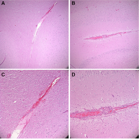 | Figure 7 Postoperative hematoxylin and eosin stain. Notes: (A, B): 4× magnification. (C, D): 10×. (A, C): insertion of prototype bevel-tipped needle (5 Fr, bevel angle 10°, fillet radius 0.25 mm). (B, D): insertion of Elekta 2.5-mm Sedan side-cutting biopsy needle. |
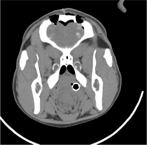 | Figure 8 Postoperative computed tomogram. Notes: Two burr holes can be seen on the top of the skull. Below the burr holes, the faint white coloration in brain represents bleeding. Left burr hole: prototype bevel-tipped needle. Right burr hole: Sedan side-cutting biopsy needle. |
Discussion
Steering of flexible bevel-tipped needles in neurosurgical applications requires tip designs with sufficient asymmetry to achieve the desired curvilinear trajectories through the brain, but such designs must also provide for the safety of brain tissue. For a given bevel-tipped needle, tissue trauma can always be reduced by increasing the fillet radius; however, increasing the fillet radius reduces the asymmetry of the needle and the surface area of the bevel, thus degrading the steering performance. This design trade-off can be managed by simulating the insertion of the needle and evaluating the stress, strain, and strain rate with respect to thresholds of these values that are associated with tissue damage. The effectiveness of this technique depends, of course, on the accuracy of the safety thresholds used for stress, strain, and strain rate during insertion of needles and similar probes into the brain. The thresholds used in the present study are merely preliminary and rough approximations obtained from other fields (e.g., vehicle crash test analysis) in the absence of more relevant data. Considerable research is needed in both simulation and experimentation in animal models in order to determine more accurate thresholds. In the future, crack growth in tissue during deeper insertions must be modeled also, followed by further validation in animal models with quantitative metrics. Crack direction (or angle) generated by blunted needles is also important, to determine the direction of the needle trajectory, and must be studied via simulation or experimentation.32,33
In the long term, this research may be relevant beyond the brain; in other applications in which blunt needles are appropriate and steerability, it may be desired.34
As more accurate brain-tissue damage criteria become available as a result of future research, finite-element model-based simulation of needle insertions into brain tissue will provide a method for the design of safe bevel-tipped needles for neurosurgical applications. These techniques can be expected to become useful as research advances in the area of quantifying iatrogenic trauma to brain tissue during insertion of needle-like probes.
Acknowledgments
This project was supported in part by the U.S. National Institutes of Health (grant no. R21EB012209) and by the Simeon M. Jones, Jr., and Katharine Reed Jones Fund and the Walter L. Copeland Fund of the Pittsburgh Foundation.
Disclosure
The authors report no conflicts of interest in this work.
References
Siegel R, Naishadham D, Jemal A. Cancer statistics, 2013. CA Cancer J Clin. 2013;63(1):11–30. | ||
Begley DJ. Delivery of therapeutic agents to the central nervous system: the problems and the possibilities. Pharmacol Ther. 2004;104(1):29–45. | ||
Riva D, Giorgi C, Nichelli F, et al. Intrathecal methotrexate affects cognitive function in children with medulloblastoma. Neurology. 2002;59(1):48–53. | ||
Roman DD, Sperduto PW. Neurophysiological effects of cranial radiation: current knowledge and future directions. Int J Radiat Oncol Biol Phys. 1995;31:983–998. | ||
Bekelis K, Radwan TA, Desai A, Roberts DW. Frameless robotically targeted stereotactic brain biopsy: feasibility, diagnostic yield, and safety. J Neurosurg. 2012;116(5):1002–1006. | ||
Niu L, Ji LY, Li JM, et al. Effect of bilateral deep brain stimulation of the subthalamic nucleus on freezing of gait in Parkinson’s disease. J Int Med Res. 2012;40(3):1108–1113. | ||
Kunwar S, Prados MD, Chang SM, et al. Direct intracerebral delivery of cintredekin besudotox (IL13-PE38QQR) in recurrent malignant glioma: a report by the Cintredekin Besudotox Intraparenchymal Study Group. J Clin Oncol. 2007;25(7):837–844. | ||
Raghavan R, Brady ML, Rodríguez-Ponce MI, Hartlep A, Pedain C, Sampson JH. Convection-enhanced delivery of therapeutics for brain disease, and its optimization. Neurosurg Focus. 2006;20:E12. | ||
Patel SJ, Shapiro WR, Laske DW, et al. Safety and feasibility of convection-enhanced delivery of Cotara for the treatment of malignant glioma: initial experience in 51 patients. Neurosurgery. 2005;56:1243–1253. | ||
Ram Z, Culver KW, Oshiro EM, et al. Therapy of malignant brain tumors by intratumoral implantation of retroviral vector-producing cells. Nat Med. 1997;3(12):1354–1361. | ||
Qureshi NH, Bankiewicz KS, Louis DN, Hochberg FH, Chiocca EA, Harsh GR. Multicolumn infusion of gene therapy cells into human brain tumors: technical report. Neurosurgery. 2000;46(3):663–668; discussion 668–669. | ||
Abayazid M, Pacchierotti C, Moreira P, Alterovitz R, Prattichizzo D, Misra S. Experimental evaluation of co-manipulated ultrasound-guided flexible needle steering. Int J Med Robot Comput Assist Surg. 2016;12:219–230. | ||
Ko SY, Rodriguez Y Baena F. Toward a miniaturized needle steering system with path planning for obstacle avoidance. IEEE Trans Biomed Eng. 2013;60(4):910–917. | ||
Cowan N, Goldberg K, Chirikjian GS, et al. Robotic needle steering: design, modeling, planning, and image guidance. In: Rosen J, Hannaford B, Satava RM, editors. Surgical Robotics: Systems, Applications and Visions. New York, NY: Springer; 2011:557–582. | ||
Frasson L, Ko SY, Turner A, Parittotokkaporn T, Vincent JF, Rodriguez y Baena F. STING: a soft-tissue intervention and neurosurgical guide to access deep brain lesions through curved trajectories. Proc Inst Mech Eng H. 2010;224(6):775–788. | ||
Burgner J, Swaney PJ, Lathrop RA, Weaver KD, Webster III RJ. Debulking from within: a robotic steerable cannula for intracerebral hemorrhage evacuation. IEEE Trans Biomed Eng. 2013;60(9):2567–2575. | ||
Grady MS, Howard III MA, Dacey Jr RG, et al. Experimental study of the magnetic stereotaxis system for catheter manipulation within the brain. J Neurosurg. 2000;93:282–288. | ||
Webster III RJ, Kim JS, Cowan NJ, Chirikjian GS, Okamura AM. Nonholonomic modeling of needle steering. Int J Robot Res. 2006;25(5–6):509–525. | ||
Engh JA, Minhas DS, Kondziolka D, Riviere CN. Percutaneous intracerebral navigation by duty-cycled spinning of flexible bevel-tipped needles. Neurosurgery. 2010;67(4):1117–1122; discussion 1122–1123. | ||
Oldfield MJ, Burrows C, Kerl J, et al. Highly resolved strain imaging during needle insertion: results with a novel biologically inspired device. J Mech Behav Biomed Mater. 2014;30:50–60. | ||
Misra S, Reed KB, Schafer BW, Ramesh KT, Okamura AM. Mechanics of flexible needles robotically steered through soft tissue. Int J Robot Res. 2010;29(13):1640–1660. | ||
Webster III RJ, Memisevic J, Okamura AM. Design considerations for robotic needle steering. Proceedings of the 2005 IEEE International Conference on. Robotics and Automation, 2005. ICRA 2005. Barcelona, Spain: IEEE; 2005:3599–3605. | ||
Morrison B 3rd, Cater HL, Wang CC, et al. A tissue level tolerance criterion for living brain developed with an in vitro model of traumatic mechanical loading. Stapp Car Crash J. 2003;47:93–105. | ||
Bain AC, Meaney DF. Tissue-level thresholds for axonal damage in an experimental model of central nervous system white matter injury. J Biomed Eng. 2000;122:615–622. | ||
Shreiber DI, Bain AC, Meaney DF. In vivo thresholds for mechanical injury to the blood-brain barrier. In: Proc. 41st Stapp Car Crash Conference. Vol; 1997:277–291. | ||
De S, Rosen J, Dagan A, Hannaford B, Swanson P, Sinanan M. Assessment of tissue damage due to mechanical stresses. Int J Rob Res. 2007;26(11–12):1159–1171. | ||
Miller K, Chinzei K. Constitutive modeling of brain tissue: experiment and theory. J Biomech. 1997;30(11–12):1115–1121. | ||
Miller K. Constitutive model of brain tissue suitable for finite element analysis of surgical procedures. J Biomech. 1999;32:531–537. | ||
Oldfield M, Dini D, Giordano G, Rodriguez Y Baena F. Detailed finite element modeling of deep needle insertions into a soft tissue phantom using a cohesive approach. Comput Methods Biomech Biomed Eng. 2013;16(5):530–543. | ||
Casanova F, Carney PR, Sarntinoranont M. Effect of needle insertion speed on tissue injury, stress, and backflow distribution for convection-enhanced delivery in the rat brain. PLoS One. 2014;9(4):e94919. | ||
National Research Council. Guide for the Care and Use of Laboratory Animals. 8th ed. Washington, DC: National Academies Press; 2011. | ||
Assaad W, Jahya A, Moreira P, Misra S. Finite-element modeling of a bevel-tipped needle interacting with gel. J Mech Med Biol. 2015;15(5):1550079. | ||
van Veen YR, Jahya A, Misra S. Macroscopic and microscopic observations of needle insertion into gels. Proc Inst Mech Eng Part H J Eng Med. 2012;226(6):441–449. | ||
Smuck M, Paulus S, Patel A, Demirjian R, Ith MA, Kennedy DJ. Transforaminal epidural injections using blunt-tip, pencil-point, and catheter-extension needles. Pain Med. 2015;16(11):2084–2089. |
 © 2017 The Author(s). This work is published and licensed by Dove Medical Press Limited. The full terms of this license are available at https://www.dovepress.com/terms.php and incorporate the Creative Commons Attribution - Non Commercial (unported, v3.0) License.
By accessing the work you hereby accept the Terms. Non-commercial uses of the work are permitted without any further permission from Dove Medical Press Limited, provided the work is properly attributed. For permission for commercial use of this work, please see paragraphs 4.2 and 5 of our Terms.
© 2017 The Author(s). This work is published and licensed by Dove Medical Press Limited. The full terms of this license are available at https://www.dovepress.com/terms.php and incorporate the Creative Commons Attribution - Non Commercial (unported, v3.0) License.
By accessing the work you hereby accept the Terms. Non-commercial uses of the work are permitted without any further permission from Dove Medical Press Limited, provided the work is properly attributed. For permission for commercial use of this work, please see paragraphs 4.2 and 5 of our Terms.