")
Back to Journals » Medical Devices: Evidence and Research » Volume 17
Research Status and Prospect of Finger Rehabilitation Machinery
Authors Zhang Z, Calderon AD, Huang X, Huang A
Received 28 July 2023
Accepted for publication 10 November 2023
Published 3 January 2024 Volume 2024:17 Pages 1—22
DOI https://doi.org/10.2147/MDER.S429206
Checked for plagiarism Yes
Review by Single anonymous peer review
Peer reviewer comments 2
Editor who approved publication: Dr Scott Fraser
Zhilin Zhang,1,2 Aldrin D Calderon,1 Xingyu Huang,1 Axin Huang1
1School of Mechanical, Manufacturing and Energy Engineering, Mapúa University, Manila, 0900, Philippines; 2School of Physics and Telecommunications Engineering, Yulin Normal University, Yulin, 537000, People’s Republic of China
Correspondence: Aldrin D Calderon, Email [email protected]
Abstract: About 80% of stroke patients have hand motor dysfunction, and wearing finger rehabilitation machinery can enable patients to carry out efficient passive rehabilitation training independently. At present, many typical finger rehabilitation machines have been developed, and clinical experiments have confirmed the effectiveness of mechanically assisted finger rehabilitation. In this paper, the finger rehabilitation machinery will be classified in the actuation mode, and the terminal traction drive/motor drive/spring drive/rope drive/memory alloy drive/electroactive material drive/hydraulic drive/pneumatic drive technology and its typical applications are analyzed. Study the structure, control methods, overlap between mechanical bending nodes and finger joints, training modes, response speed, and driving force of various types of finger rehabilitation machinery. The advantages and disadvantages of various actuation methods of finger rehabilitation machinery are summarized. Finally, the difficulties and opportunities faced by the future development of finger rehabilitation machinery are prospected. In general, with the continuous improvement of quality of life, stroke patients need flexible, segmented control, accurate bending, multi-training mode, fast response, and good driving force finger rehabilitation machinery. This will also be a future hot research direction.
Keywords: fingers, machinery, rehabilitation, actuation
Introduction
Motor dysfunction occurs in 80% of stroke patients,1,2 which places a burden on patients and their families. Scientific studies have shown that continuous passive rehabilitation exercise therapy can effectively prevent muscle atrophy, promote the remodeling of nervous system motor function,3–9 prevent tendon adhesion and joint stiffness, and improve blood circulation and joint rehabilitation effects at the exercise site, to achieve the treatment of finger.10,11 Finger rehabilitation machinery has become a key research direction of international rehabilitation engineering and robotics, and patients can carry out efficient autonomous rehabilitation training by wearing manipulators.12–14
Research Status
There have been many typical research results in finger rehabilitation machinery, and clinical experiments have also shown that mechanical-assisted hand rehabilitation is effective.15–22 According to the material and structural design, finger rehabilitation machinery can be divided into rigid exoskeleton and flexible wearable.23–30 In the early stage, finger function rehabilitation robots mostly adopted rigid exoskeleton structures and used motor-driven connecting rods or gear meshing to control the joints of the fingers for round-trip movement for rehabilitation. However, the rigid structure is complex, the load weight is large, the pertinence is strong, and the adaptability is not high.31–41 At present, flexible finger rehabilitation robots pay more attention to comfort and safety and have better research prospects.42–48
If the finger rehabilitation machinery is classified by the actuation method, it can be divided into: end traction drive,49–53 motor drive,54–59 spring drive,60–63 rope drive,64–70 memory alloy drive,71–76 electroactive material drive,77–79 hydraulic drive80–82 and pneumatic drive.83–88 Each actuation mode has its application characteristics, this paper will analyze the above driving methods and their typical applications. Study the structure, control methods, overlap between mechanical bending nodes and finger joints, training modes, response speed, and driving force of various types of finger rehabilitation machinery. Summarize the advantages and disadvantages of various actuation methods of finger rehabilitation machinery, and discuss the future development direction of finger rehabilitation machinery.
Mechanical Classification of Finger Rehabilitation
End Traction Type
Researchers at the Medical University of Graz in Austria have designed an end traction-driven finger rehabilitation machinery (AMADEO),89 as shown in Figure 1. This is a full-fledged finger rehabilitation machinery. The robot is used to complete the flexion and extension of the fingers in a plane and simplifies multi-degree-of-freedom motion to single-degree-of-freedom linear motion, reducing the number of drive motors used. AMADEO is equipped with finger sleeves with magnets that adhere to the fingertips for linear movement. The magnet suction is not strong, and when the patient performs a large reaction force on the robot, the magnet will separate to protect the patient’s fingers. This finger rehabilitation machinery uses a rigid structure. The control method of overall finger bending was used. The mechanical bending nodes and the finger joints do not coincide. Can only achieve finger bending and stretching training. Fast response speed, 0-second response. The driving force at the finger end is determined by the motor output power.
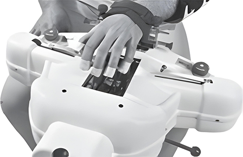 |
Figure 1 End traction-driven finger rehabilitation machinery. Note: Copyright ©2013. Taylor & Francis Ltd. Pinter D, Pegritz S, Pargfrieder C, et al. Enzinger C.Exploratory study on the effects of a robotic hand rehabilitation device on changes in grip strength and brain activity after stroke.Topics in Stroke Rehabilitation. 2013;20(4):308–316, reprinted by permission of the publisher (Taylor & Francis Ltd, (http://www.tandfonline.com)).89 |
Motor Driven Type
Researchers at Hefei University of Technology in China designed a wearable rehabilitation exoskeleton manipulator based on the biological characteristics of the human hand.90 As shown in Figure 2, the exoskeleton mechanism is placed on the back of the operator’s hand by considering the palm grip characteristics, and the compact but very high torque servo motor is selected as the drive, using a compact and tight RSSR four-link structure with accurate power transmission to transmit motion. The finger training mechanism uses a linkage ABCD similar to the one in Figure 2 to form an RSSR four-link structure, which is designed to effectively reduce mechanical weight.
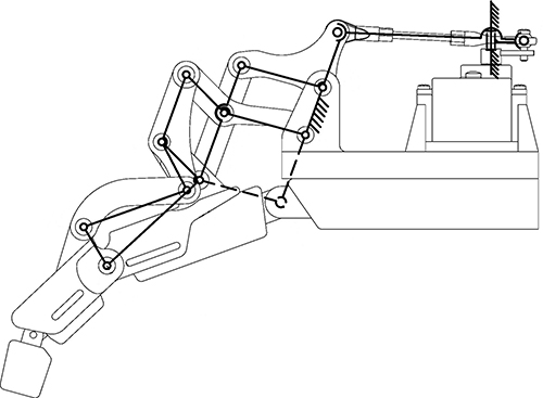 |
Figure 2 A wearable rehabilitation exoskeleton robotic arm. Note: Reproduced from Ma W, Xiao F,Wang Y. Design and analysis of a wearable exoskeleton rehabilitation manipulator. Journal of Hefei University of Technology (Natural Science Edition). 2022;45(03):307–314.90 |
This finger rehabilitation machinery, using a single motor drive and a double parallelogram mechanism to drive finger movement, is simple to operate, and the fingers of the manipulator have only one degree of freedom. Through kinematics analysis and simulation studies, the rotation relationship of the mechanism driving the finger is obtained (as shown in Figure 3). Rehabilitation test studies have shown that the manipulator has a simple structure, good wearing adaptability, and a finger movement angle with a repeatability error of less than 5%, which can ensure the space of the soft tissue of the mechanism and finger joint, and avoid adjacent finger friction damage. Therefore, the rehabilitation machinery can perform better rehabilitation training on fingers. This finger rehabilitation machinery uses a rigid structure. The control method of overall finger bending was used. The mechanical bending nodes and the finger joints do not coincide. Can only achieve finger bending and stretching training. Fast response speed, 0-second response. The driving force at the finger end is determined by the motor output power.
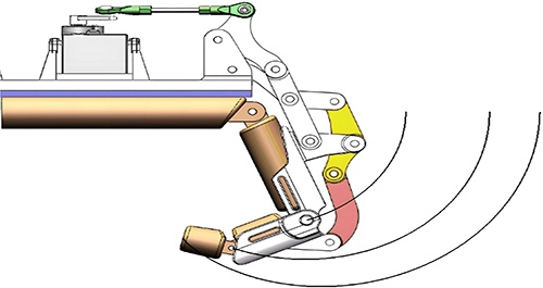 |
Figure 3 Mechanism motion trajectory. Note: Reproduced from Ma W, Xiao F,Wang Y. Design and analysis of a wearable exoskeleton rehabilitation manipulator. Journal of Hefei University of Technology (Natural Science Edition). 2022;45(03):307–314.90 |
Li Guotao et al of the Institute of Automation of the Chinese Academy of Sciences designed an untethered adaptive thumb exoskeleton for delicate rehabilitation assistance.91 The structure of this finger rehabilitation training machinery is shown in Figure 4, consisting of three joint motors, two sliders, and multiple connecting rods. O represents the origin of the coordinate system, X represents the positive X-axis direction of the coordinate system, Y represents the positive Y-axis direction of the coordinate system, and Z represents the positive Z-axis direction of the coordinate system. A1 and A2 represent moving components. A3 represents rotating component. Motor 1 can rotate around the Z-axis along the red arrow. Motor 2 can rotate around the Y-axis along the red arrow. Motor 3 can rotate around the Y-axis along the red arrow. A1 can move left and right along the red arrow. A2 can move back and forth along the red arrow. Among them, by moving the slider A1, the rehabilitation training machinery and the finger can keep on the same horizontal line, and the position of the rehabilitation training machinery and the finger can be calibrated to avoid mechanical damage to the finger. Through the reciprocating rotation of Motor 1, finger swing rehabilitation training can be realized. Motor 2 and motor 3 simulate the turning joint of the finger, which can independently drive any section of finger bending training alone, and finally realize the rehabilitation training of segmented finger bending. During the rotation of Motor 2 and Motor 3, the driving force is applied to the proximal phalanx of the finger by slider A2, and the driving force is applied to the distal phalanx of the finger by A3, in this way, the problem of no overlap between the mechanical bending node and the finger joint can be effectively solved. This finger rehabilitation machinery uses a rigid structure. The control method of finger segment bending was used. The mechanical bending nodes coincide with the finger joints. It can not only achieve finger bending and stretching training but also achieve swing training. Fast response speed, 0-second response. The driving force at the finger end reached 12N.
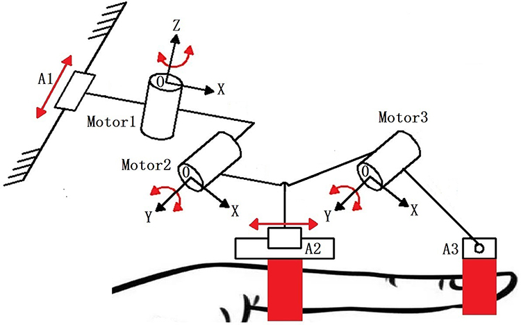 |
Figure 4 An untethered adaptive thumb exoskeleton for delicate rehabilitation assistance. Notes: A1 and A2 represent moving components. A3 represents the rotating component. O represents the origin of the coordinate system, X represents the positive X-axis direction of the coordinate system, Y represents the positive Y-axis direction of the coordinate system, and Z represents the positive Z-axis direction of the coordinate system. |
Spring Driven Type
Researchers at Beijing University of Posts and Telecommunications in China have designed a rehabilitated flexible hand exoskeleton manipulator, whose fingers use a flexible spiral drive mechanism as the main drive mechanism.92 As shown in Figure 5, the flexible finger can complete the unidirectional bending and straightening action by limiting the bending direction of the flexible spiral mechanism. The red lines represent the range of bending angles. θMCP represents the bending angle of the metacarpophalangeal joint, θPIP represents the bending angle of the interphalangeal joint, and θDIP represents the bending angle of the fingertip joint.
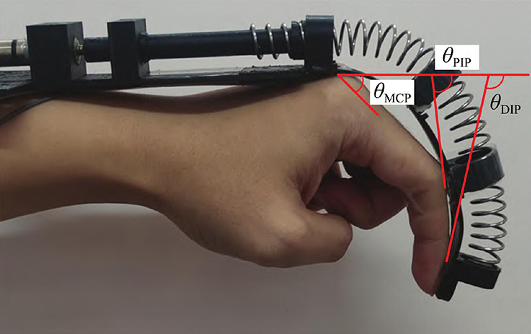 |
Figure 5 A finger rehabilitation machinery based on a flexible spiral drive. Notes: The red lines represent the range of bending angles. θMCP represents the bending angle of the metacarpophalangeal joint, θPIP represents the bending angle of the interphalangeal joint, and θDIP represents the bending angle of the fingertip joint. Reproduced from Zhang Y, Song Z, Chu M. Design and realization of flexible hand for rehabilitation. Journal of Huazhong University of Science and Technology (Natural Science Edition). 2023;51(06):36–40. DOI:10.13245/j.hust.230606.92 |
Figure 6 shows the structure of a single flexible finger of a manipulator. As shown in Figure 6a, the flexible finger is composed of five parts: flexible fingertips, spring, spring strip, screw, and motor interface. Among them, the spring is fixed at the knuckle of the front end of the flexible finger sleeve, while the other end is connected with the screw, and the lower part of the flexible finger sleeve is installed with a spring plate, which can provide a unidirectional bending constraint for the entire flexible finger and form a flexible spiral drive. Figure 6b is a cross-sectional view of a flexible finger, which consists of four parts: front end knuckles, middle knuckles, tail knuckles, and finger sleeve shell, using the finger sleeve shell to keep each part fixed. Robotic fingers can be bent in both directions: when the motor rotates in a positive direction, the spring extends relative to the screw towards the front end knuckle, but the spring is squeezed due to the limitation of the flexible finger sleeve front knuckle. This results in the generation of an axial thrust at the anterior knuckles, which drives the flexible finger to bend in a positive direction; conversely, when the motor rotates in the opposite direction, the spring moves backward relative to the screw and slowly retreats into the screw. The spring is connected to the front knuckle, and the front knuckle is pulled by the spring retreat, and the flexible finger will be bent and deformed in the opposite direction.
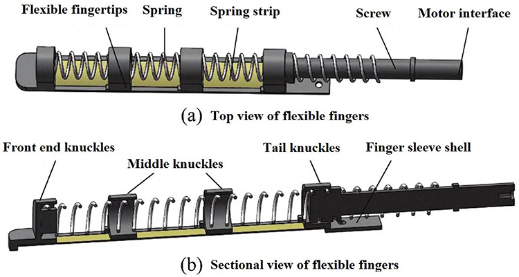 |
Figure 6 Schematic diagram of flexible finger mechanism. Notes: (a) Top view of flexible fingers, which is composed of five parts: flexible fingertips, spring, spring strip, screw, and motor interface. (b) Sectional view of flexible fingers, which consists of four parts: front end knuckles, middle knuckles, tail knuckles, and finger sleeve shell, using the finger sleeve shell to keep each part fixed. Reproduced from Zhang Y, Song Z, Chu M. Design and realization of flexible hand for rehabilitation. Journal of Huazhong University of Science and Technology (Natural Science Edition). 2023;51(06):36–40. DOI:10.13245/j.hust.230606.92 |
In this study, by simplifying the finger model, the research team established a flexible finger-bending mechanical model and explored the kinematic relationship between the finger end bending angle and the number of spring rotation turns. Finally, the flexible manipulator was developed and its bending and load capacity was verified by experiments. This finger rehabilitation machinery uses a flexible structure. The control method of overall finger bending was used. The mechanical bending nodes and the finger joints do not coincide. Only to achieve finger bending and stretching training. Fast response speed, 0-second response. The driving force of the finger is determined by the number of motor turns.
Researchers at Xi’an Jiaotong University in China have designed a new multisegment continuous structure exoskeleton finger rehabilitation robot,93 as shown in Figure 7, which is composed of spring plates, linear motors, and multiple continuous structures. The mechanism uses a single linear motor to apply driving force, bend the spring plate, and drive the deformation of a multisegment continuous structure, enhancing the flexibility of muscles and joints through finger bending/stretching training, thereby improving finger movement, Figure 8 shows the structure and working principle of the mechanism in detail. h represents the height of the spring. l1, l2, l3, d1, d1, d1 represent the length of each segment of the structure. θ1 represents the bending angle of the metacarpophalangeal joints, θ2 represents the bending angle of the proximal phalangeal joint, and θ3 represents the bending angle of the distal phalangeal joint. Internally composed of linear motor, leaf spring, and multi-segment continuum. To improve the compliance of the finger rehabilitation machinery, the machinery adopts spring plates and a multistage continuous structure. The use of a spring plate and multistage continuous structure makes the whole finger rehabilitation machinery have good compliance so that the interaction between finger rehabilitation machinery and human fingers is safer, this device can convert the linear movement of the motor into the rotation movement of finger joints, the rotation angle is large enough, can adapt to different stages of rehabilitation training. However, the bending/stretching effect of the mechanical finger of the spring rotation drive type is not too sensitive. This finger rehabilitation machinery uses a flexible structure. The control method of overall finger bending was used. The mechanical bending nodes and the finger joints coincide. Only to achieve finger bending and stretching training. Fast response speed, 0-second response. The driving force of the finger end is determined by the extension of the linear motor, and the maximum leading driving force of the finger produced by the motor using a 50 mm stroke is 17.49N.
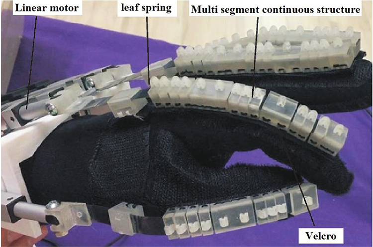 |
Figure 7 Multi-segment continuous structure hand functional rehabilitation exoskeleton robot. Note: Reproduced from Li M, Chen J, He B, et al. Motion Planning and Structure Optimization of a Multi-Segment Mechanism-Based Hand Rehabilitation Exoskeleton. Journal of Xi’an Jiaotong University. 2019;53(10):1–9.93 |
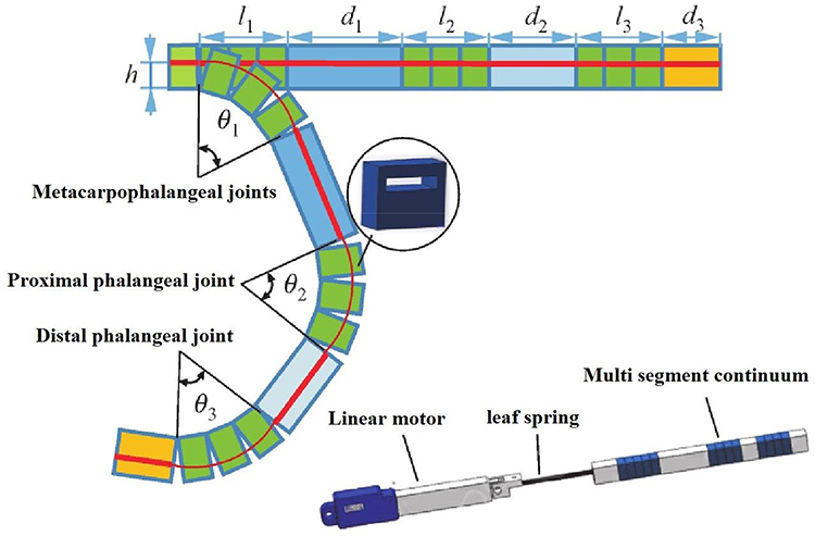 |
Figure 8 Schematic diagram of bending motion. Notes: On the left side of the image, θ1 represents the bending angle of the metacarpophalangeal joints, θ2 represents the bending angle of the proximal phalangeal joint, and θ3 represents the bending angle of the distal phalangeal joint. H represents the height of the spring. l1, l2, l3, d1, d2, d3 represent the length of each segment of the structure. On the left side of the image, the interior of the bending component is composed of linear motor, leaf spring, and multi segment continuum. Reproduced from Li M, Chen J, He B, et al. Motion Planning and Structure Optimization of a Multi-Segment Mechanism-Based Hand Rehabilitation Exoskeleton. Journal of Xi’an Jiaotong University. 2019;53(10):1–9.93 |
Jiang Jingang and others from Harbin University of Science and Technology in China have designed finger rehabilitation training machinery equipped with a new elastic torque sensor.94 As shown in Figure 9, the torque sensor was made according to the requirements of finger rehabilitation training, and the researchers chose a torsion spring based on the Archimedes spiral. The torque sensor was made from this torsion spring. The spring material uses 65-Mn material with good elasticity. The torque sensor reduces the volume torque ratio by 54.25% and its weight by 57.7%. The servo motor connects to the input of the torque sensor and provides rotational power. The input terminal transmits the rotating power directly to the output terminal through the torsion spring. The output end is connected to the angle sensor, which can detect the rotation angle of the output end in real-time. At the same time, the output end is connected to the connecting rod, through the rotation of the output end, drives the connecting rod to move together, the connecting rod can drive the finger to achieve bending training. This finger rehabilitation machinery uses a flexible structure. The control method of overall finger bending was used. The mechanical bending nodes and the finger joints do not coincide. Can only achieve finger bending and stretching training. Fast response speed, 0-second response. The driving force at the finger end is determined by the motor output power.
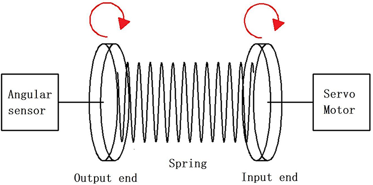 |
Figure 9 Miniature elastic torque sensor for index finger exoskeletons. |
Rope Driven Type
Researchers at Pusan National University in South Korea have designed and developed a wire-controlled exoskeleton finger rehabilitation training robot,95 as shown in Figure 10, this robot uses a four-link structure to form an exoskeleton joint system, each finger is driven by a linear motor, and the motor transmits the force to the four-link through a flexible cable. The flexible cable passes through the exoskeleton structure and is pulled by the motor, controlling the rotation of each exoskeleton joint to achieve finger bending/stretching training. In addition, the finger rehabilitation robot is also equipped with force sensors and angle sensors, which measure the strength of the fingers and the angle of the joints, and provide real-time feedback to facilitate the assessment of the patient’s recovery. This finger rehabilitation machinery uses a flexible structure. The control method of overall finger bending was used. The mechanical bending nodes coincide with the finger joints. Only to achieve finger bending and stretching training. Slow response speed, with a 3-second response. The driving force of the finger is determined by the number of motor turns.
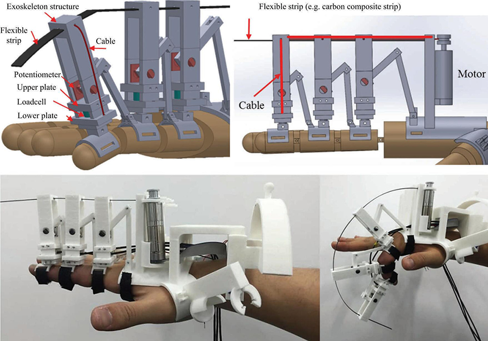 |
Figure 10 A wire-controlled exoskeleton finger rehabilitation training robot. Note: Copyright ©2017. Springer Nature. Reproduced from Kim S, Lee J, Bae J. Analysis of Finger Muscular Forces using a Wearable Hand Exoskeleton System. Journal of Bionic Engineering. 2017;14(4):680–691.95 |
Researchers at Seoul National University in South Korea have designed a rope-driven soft rehabilitation robot,96 Exo-Glove, which uses soft silicone material so that it can better adapt to the shape of the patient’s hand. The robot has a lightweight and flexible structure that can help patients regain the ability to capture objects. The rope is embedded in the silicone glove and drives the movement of the glove by the motor driving the contraction of the rope, and the patient’s hand can move widely. The main purpose of the rehabilitation robot is to help patients assist in training while completing daily basic movements, but it can only carry out passive rehabilitation training. The disadvantage of this manipulator is that there is less freedom and the training movement is more single. This finger rehabilitation machinery uses a flexible structure. The control method of overall finger bending was used. The mechanical bending nodes and the finger joints do not coincide. Only to achieve finger bending and stretching training. The response speed is average, with 0.8 seconds of response. The driving force of the finger end reached 10.3N.
Memory Alloy Driven Type
The Hamburg laboratory in Germany has developed a flexible exoskeleton imitation muscle glove,97 as shown in Figure 11, the device simulates human tendon movement, using a shape memory alloy spring as an actuator, and driving the traction rope through the contraction of the alloy wire, to complete the finger flexion and extension movement. As shown in Figure 12, the front and back of the finger sleeve are connected to a shape memory alloy spring. As shown in Figure 12a, in the initial state, the spring produces a certain stretch. The back of the finger is an extension SMA spring actuator active. In front of the finger is the inactive SMA spring actuator. The blue arrow represents the direction of force. The current finger is in an extension state; As shown in Figure 12b, when the current spring is heated, the spring will contract and deform. The flexion SMA spring actuator active on the front of the finger. On the back of the finger is an inactive SMA spring actuator. The red arrow represents the direction of force. Finally, the fingertips will undergo directional bending deformation. The current finger is in a flexion state. The weight of the glove does not exceed 100g, and the patient can use it lightly. Application experiments show that the device can achieve a similar range of motion as normal human hands, and can perform a variety of grasping actions, the disadvantage is that the force output of the shape memory alloy spring is small, and the response execution is a bit delayed. This finger rehabilitation machinery uses a flexible structure. The control method of overall finger bending was used. The mechanical bending nodes and the finger joints do not coincide. Can only achieve finger bending and stretching training. The response was slow, with a 2–3 second response. The driving force of the finger end reached 11N.
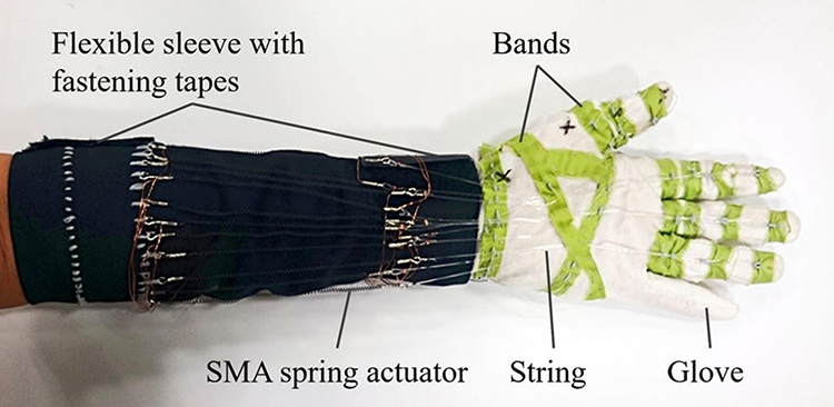 |
Figure 11 Memory alloy driven finger rehabilitation machinery. Note: Copyright ©2017. Springer Nature. Reproduced from Yao Z, Linnenberg C, Argubi-Wollesen A, Weidner R, Wulfsberg JP. Biomimetic design of an ultra-compact and light-weight soft muscle glove. Production Engineering. 2017;11(6):731–743.97 |
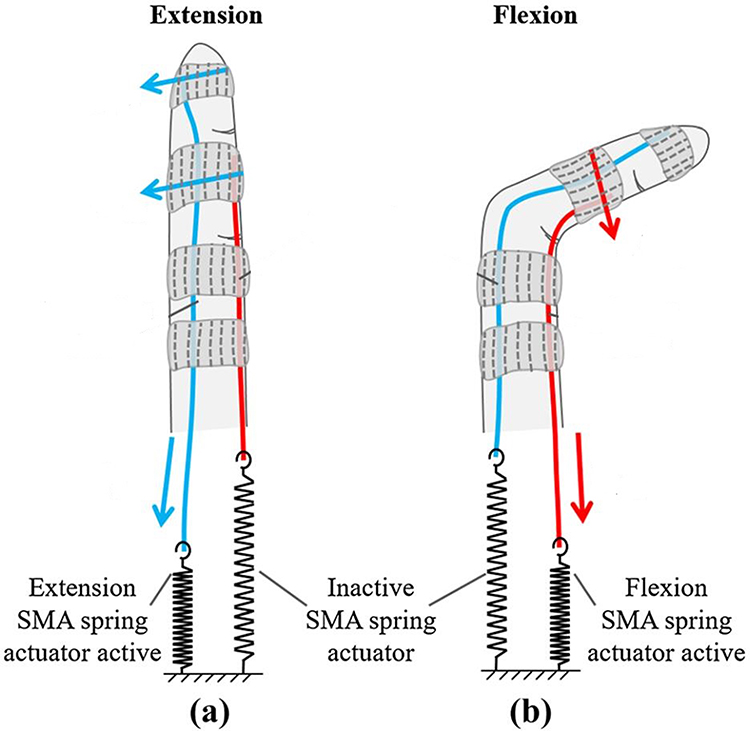 |
Figure 12 Flexion and extension mechanism of the muscle glove. Notes: (a) In the initial state, the spring produces a certain stretch. The back of the finger is an extension SMA spring actuator active. In front of the finger is the inactive SMA spring actuator. The blue arrow represents the direction of force. The current finger is in an extension state; (b) when the current spring is heated, the spring will contract and deform. The flexion SMA spring actuator active on the front of the finger. On the back of the finger is an inactive SMA spring actuator. The red arrow represents the direction of force. Copyright ©2017. Springer Nature. Reproduced from Yao Z, Linnenberg C, Argubi-Wollesen A, Weidner R, Wulfsberg JP. Biomimetic design of an ultra-compact and light-weight soft muscle glove. Production Engineering. 2017;11(6):731–743.97 |
Researchers at China’s Northeast Forestry University have designed a rehabilitative exoskeleton that drives fingers with shape memory alloys.74 SMA (shape memory alloy) wire is used as an actuator. The finger rehabilitation machinery consists of a hand actuator and an actuating device, wherein the actuating device includes a guide wire block, a fixed plate, and an SMA wire, as shown in Figure 13. To increase the displacement output generated by the drive device, a reciprocating wire structure is adopted to convert the strain of the SMA wire into the displacement of the wire rope. The lightweight glove was designed as a hand exoskeleton structure, and Teflon guide tubes were installed in the middle of each phalange, which reduced the resistance between the glove exoskeleton and the traction wire rope, ensuring a high fit between the robotic hand and the patient’s finger when completing the bending and stretching movements. The SMA wire is installed on the upper plate and lower plate of the drive unit, respectively, retaining a certain amount of telescopic space. The SMA wire of the upper plate connects one end of the wire rope and then passes through the Teflon guide tube on the back of the glove, and the other end of the wire rope is fixed to the fingertip of the glove. Similarly, the SMA wire of the lower plate connects one end of the wire rope and then passes through the Teflon guide pipe on the front of the glove, and the other end of the wire rope is also fixed on the fingertip of the glove. SMA wire is driven by electric heating mode, using electric heating SMA wire, deforming SMA wire, pulling the wire rope to produce displacement, heating the SMA wire of the upper plate and the lower plate by alternating electricity, and the wire rope on both sides is pulled to complete the rehabilitation exercise training of finger bending/stretching. This finger rehabilitation machinery uses a flexible structure. The control method of overall finger bending was used. The mechanical bending nodes and the finger joints do not coincide. Only to achieve finger bending and stretching training. The response was slow, 1 second response. The driving force of the finger end reached 16N.
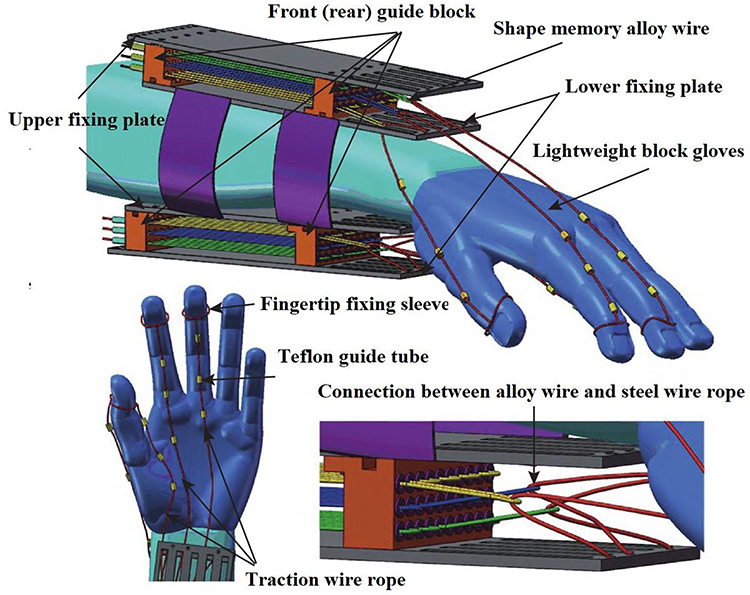 |
Figure 13 A rehabilitative exoskeleton that drives fingers with shape memory alloys. Note: Reproduced from Wang Y, Lv P, Zheng S, Wang B, Li J. Design of exoskeleton for functional rehabilitation of fingers driven by shape memory alloy. Journal of Zhejiang University (Engineering Edition). 2022;56(12):2340–2348.74 |
Electroactive Material Driven Type
Researchers at the Egypt-Japan University of Science and Technology in Japan have designed a new hand rehabilitation system that uses electroactive materials as actuators,98 as shown in Figure 14. The device is suitable for the rehabilitation of a single finger. The system uses a rope mechanism instead of a traditional rigid linkage, and the degree of freedom of the entire device is one. The essence of an electroactive material actuator is a capacitor that contains two electrodes sandwiched in a soft elastic film. When a voltage is applied between these two electrodes, an electrostatic force is generated that pulls the polymer layer. This process is caused by the positive charge on one electrode attracting the negative charge on the other. To pull the finger for a bending motion, which requires giving the cable pull, the researchers designed an electroactive material actuator named a spring-coiled electroactive material actuator, as shown in Figure 15, which can roll with a high voltage applied and then return to its original length after the voltage is released. Electroactive material actuators can use voltage control to stretch and retract the cable to achieve finger-bending training. The most obvious disadvantage of this device is its slow response speed and single movement. This finger rehabilitation machinery uses a flexible structure. The control method of overall finger bending was used. The mechanical bending nodes coincide with the finger joints. Only to achieve finger bending and stretching training. Fast response speed, 0-second response. The driving force of the finger end reached 4.35N.
 |
Figure 14 Electroactive material-driven finger rehabilitation machinery. Note: Reproduced from Amin H, Assal SFM, Iwata H. A new hand rehabilitation system based on the cable-driven mechanism and dielectric elastomer actuator. Mechanical Sciences. 2020;11(2):357–369.98 |
 |
Figure 15 Electroactive material actuator. Note: Reproduced from Amin H, Assal SFM, Iwata H. A new hand rehabilitation system based on the cable-driven mechanism and dielectric elastomer actuator. Mechanical Sciences. 2020;11(2):357–369.98 |
Hydraulically Driven Type
Researchers at Harvard University in the United States have designed a soft robotic glove,99 mainly for patients to restore the ability to grasp objects through training, as shown in Figure 16. This rehabilitation glove utilizes a soft actuator consisting of an elastomer cavity and a fiber reinforcement to create specific flexion and stretching under liquid pressure.
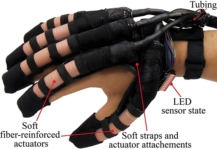 |
Figure 16 Hydraulically driven finger rehabilitation machinery. Note: Reprinted from Robotics and Autonomous Systems, 73, Polygerinos P, Wang Z, Galloway KC, Wood RJ, Walsh CJ, Soft robotic glove for combined assistance and at-home rehabilitation, 135–143, Copyright ©2015, with permission from Elsevier.99 |
A single software actuator is pasted and synthesized by an elastomer cavity and a limiting strain layer, and then wound with 2 mechanical springs, as shown in Figure 17, which can enhance the axial extension effect of the software actuator, reduce the diameter expansion, thereby enhancing the output of the soft actuator, by applying hydraulic pressure to the elastomer cavity, because the elastomer cavity becomes longer, and the limiting strain layer remains unchanged, the extension difference between the two can achieve the bending deformation of the finger module.
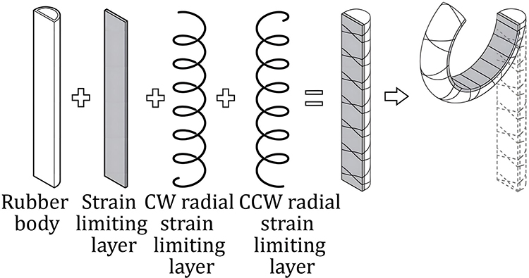 |
Figure 17 Disassembly and assembly diagram of the actuator. Note: Reprinted from Robotics and Autonomous Systems, 73, Polygerinos P, Wang Z, Galloway KC, Wood RJ, Walsh CJ, Soft robotic glove for combined assistance and at-home rehabilitation, 135–143, Copyright ©2015, with permission from Elsevier.99 |
The hydraulic actuator is mounted on the back of the hand, the flexible robot can flex/extend the fingers, and the flexible glove is better, lighter, and better fit than the traditional rigid robot. However, the robot cannot perform targeted rehabilitation training on individual joints of the fingers, and each finger has only one active degree of freedom. This finger rehabilitation machinery uses a flexible structure. The control method of overall finger bending was used. The mechanical bending nodes and the finger joints do not coincide. Only to achieve finger bending and stretching training. Fast response speed, 30ms seconds response. The driving force of the finger end reached 8N.
Pneumatically Driven Type
Researchers at Harvard University in the United States calculated a fabric-based pneumatic robotic glove that mainly treats hand movement disorders after spinal cord injury,100 as shown in Figure 18. The glove is pneumatically actuated, has semicircular sections at the joints, is covered with fiberglass cloth, and is wrapped with fiber threads. After inflation, the glove can bend and drive finger movement, and its material and drive make it excellent flexibility without flexible control, and can adapt to different finger rehabilitation training.
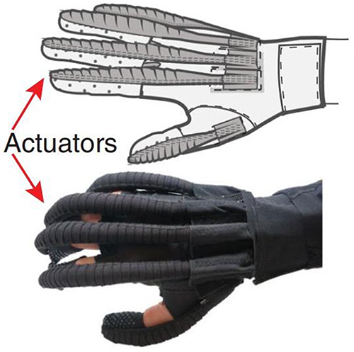 |
Figure 18 A fabric-based pneumatic robotic glove. Note: Reproduced from Cappello L, Meyer JT, Galloway KC, et al. Assisting hand function after spinal cord injury with a fabric-based soft robotic glove. Journal of Neuro Engineering and Rehabilitation. 2018;15(1):59 (https://creativecommons.org/licenses/by/4.0/).100 |
The design of a single finger is a three-layer package design, as shown in Figure 19, with two spaces, the upper space to mount the soft cavity and the lowest space to mount the strain-limiting material. Finally, the stretchability of the upper layer is better, the stretchability of the lower layer is poor, and the different elongation rates of the upper and lower layers of the structure are used to drive finger movement by using the different elongation rates of the upper and lower layers when inflated, and the greater the air pressure, the greater the curvature, as shown in Figure 20. Because this manipulator is too soft, its unterminated output force is usually very small, and the rigidity is poor, which is not suitable for treating patients with too stiff fingers. This finger rehabilitation machinery uses a flexible structure. The control method of overall finger bending was used. The mechanical bending nodes and the finger joints do not coincide. Only to achieve finger bending and stretching training. Fast response speed, and 0-second response. The driving force of the finger end reached 6.6N.
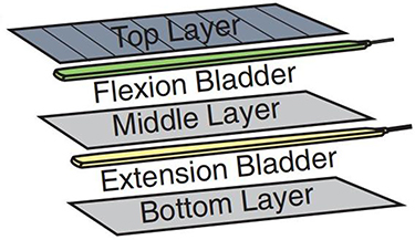 |
Figure 19 Structure of different fabric layers. Note: Reproduced from Cappello L, Meyer JT, Galloway KC, et al. Assisting hand function after spinal cord injury with a fabric-based soft robotic glove. Journal of Neuro Engineering and Rehabilitation. 2018;15(1):59 (https://creativecommons.org/licenses/by/4.0/).100 |
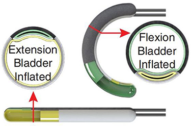 |
Figure 20 The relationship between hydraulic pressure and finger bending motion. Note: Reproduced from Cappello L, Meyer JT, Galloway KC, et al. Assisting hand function after spinal cord injury with a fabric-based soft robotic glove. Journal of Neuro Engineering and Rehabilitation. 2018;15(1):59 (https://creativecommons.org/licenses/by/4.0/).100 |
Researchers at Beihua University in China have designed a wearable glove rehabilitation device based on a barometric actuator.101 The rehabilitation machinery refers to bionics, modeled on the shape of the human hand, using an air pressure actuator, the structure of which is shown in Figure 21, the rehabilitation machinery includes 5 fingers and 6 degrees of freedom. To ensure the grip and flexibility of the rehabilitation device, a dual-chamber air pressure actuator is used for the thumb and a single-chamber air pressure actuator for the remaining fingers. The glove is made of elastic fabric, the air pressure actuator is mounted on the back of the hand, the air intake end is fixed at the base of the finger, and it is bound by a wrist strap.
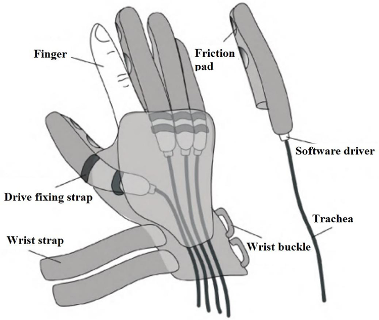 |
Figure 21 Pneumatic soft rehabilitation device. Note: Reproduced from Li K, Bi X, Li L, Zhao Y. A wearable hand-functional rehabilitation device based on pneumatic software drivers. Machine Tool and Hydraulic. 2022;50(23):30–34.101 |
Figure 22 shows the structure of the air pressure actuator, the interior is a network structure of multiple small air cavities, each small air cavity is independent, the bottom of the small air cavity is connected to the same air passage, and finally merged into one air cavity. When air pressure is injected into the airway, the air chamber expands. As shown in Figure 22a, the single-chamber air pressure actuator contains one air cavity and one airway. The length is l01, the width is w1. Single cavity drive is composed of an air cavity, air flue, and confinement layer; As shown in Figure 22b, the dual-chamber air pressure actuator consists of two airways and two airways, and the air chamber is divided into two independent air chambers by a central spacer. The length is l02, the width is w1; Dual cavity drive is composed of air cavity 1, air cavity 2, bulkhead, air flue, and confinement layer; After the air pressure is introduced, the small air cavity of each grid expands and the inner wall thins, resulting in the overall axial expansion of the air cavity, due to the existence of the strain limiting layer, the air cavity as a whole will be bent and deformed, helping the patient’s finger bending movement for rehabilitation training. Air pressure actuators enable active bending and passive recovery of fingers. Due to its simple control, flexible treatment, and fast response, it has attracted increasing researchers. This finger rehabilitation machinery uses a flexible structure. The control method of overall finger bending was used. The mechanical bending nodes and the finger joints do not coincide. Only to achieve finger bending and stretching training. Fast response speed, and 0-second response. The driving force of the finger end reached 15N.
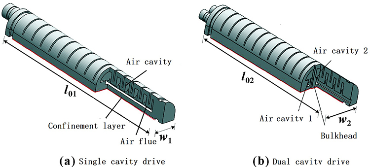 |
Figure 22 Air cavity drive structure. Notes: (a) The single-chamber air pressure actuator contains one air cavity and one airway. The length is l01, the width is w1. Single cavity drive is composed of an air cavity, air flue, and confinement layer; (b) the dual-chamber air pressure actuator consists of two airways and two airways, and the air chamber is divided into two independent air chambers by a central spacer. The length is l02, the width is w2. Dual cavity drive is composed of air cavity 1, air cavity 2, bulkhead, air flue, and confinement layer. Reproduced from Li K, Bi X, Li L, Zhao Y. A wearable hand-functional rehabilitation device based on pneumatic software drivers. Machine Tool and Hydraulic. 2022;50(23):30–34.101 |
Comparative Analysis
The most important task of finger rehabilitation machinery is to drive the fingers for bending, stretching, and swinging training. Scientific studies have shown that continuous passive rehabilitation exercise therapy can effectively prevent muscle atrophy, promote the remodeling of nervous system motor function,3–9 prevent tendon adhesion and joint stiffness, and improve blood circulation and joint rehabilitation effects at the exercise site, to achieve the treatment of finger of stroke patients.10,11 Finger rehabilitation machinery of different types has its characteristics. This paper studies and analyzes various finger rehabilitation machinery in references 89–102. The research contents include structure, control method, coincidence degree of mechanical bending nodes and finger joints, training mode, response speed, and driving force. Then the specific situation is made as a statistic, as shown in Table 1.
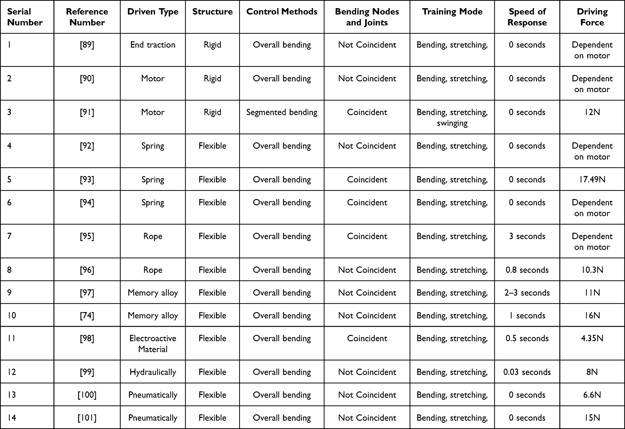 |
Table 1 Comparison of Different Actuation Methods |
Number 1 is the end traction-driven finger rehabilitation machinery. It moves through a straight line of traction of the motor on the finger. It is a rigid structure, realizing finger bending and stretching movement in the plane, can only achieve the whole section of bending control, and can not control the bending of individual joints. The training principle is to bend the finger through linear traction. If the finger joint is on the same axis, it is easy to cause finger strain;
Number 2 is a motor-driven finger rehabilitation machinery. It uses a torque-high steering gear as an actuator, through a fixed link structure to push the fingers to bend and stretch training. However, the link is rigid and fixed, which can not adapt to the size of everyone’s finger joints. This results in misalignment of the rotation site of the link and the finger joint of the patient. If the connecting rod cannot fully fit the patient’s fingers, there will be a certain dislocation error, resulting in the connecting rod hurting the patient’s fingers when rotating. It can only achieve the whole segment bending control, and cannot control the bending of individual joints;
Number 3 is also a motor-driven finger rehabilitation machinery. It uses the segmented control of three motors, which can separately control the individual joints of the finger bending training. Through the movement adjustment of the slider, the mechanical bending node and the finger joint coincide, which is beneficial to protect the patient’s finger bending training. This finger rehabilitation machinery can also achieve left and right swing training, but the disadvantage is that the whole is rigid structure;
Numbers 4–6 are spring-driven finger rehabilitation machinery. They are all flexible structures that use spring rotation and push to bend their fingers. They can achieve finger bending and stretching training, but can only achieve the whole section of bending control, unable to control the bending of individual joints. Number 4 uses rotational extrusion to achieve spring deformation. Number 5 is applied to push extrusion to achieve spring deformation. The above two kinds of mechanical bending nodes and finger joints do not coincide, which makes it easy to hurt the fingers and brings safety risks to patients. Number 6 is the direct use of a spring to transfer the rotation, the mechanical bending node, and the finger joint overlap, which is beneficial to protect the finger.
Numbers 7–8 are the rope-driven finger rehabilitation machinery. They are flexible structures that use ropes to pull the mechanical fingers to bend. This driving mode, like the end traction drive, can only achieve the whole segment bending control and cannot control the bending of individual joints. When the joint of the finger is on the same axis, it is easy to cause the finger straight strain, or bending deformation failure. They fit poorly to the finger joints, not to ensure that all the finger joints can bend accurately. The rope-driven finger rehabilitation machinery has a delay, the response speed of number 7 is 3 seconds, and the response speed of number 8 is 0.8 seconds, unable to respond quickly to bending;
Numbers 9–10 are memory alloy-driven finger rehabilitation machinery. They use the principle of memory alloy temperature sensitivity to realize the expansion deformation of memory metal by controlling the temperature change. They use deformation to drive the connected materials to realize the bending training of fingers. Due to the thermal inertia of its metal, the biggest disadvantage of this driving mode is that the response speed is too slow, and the repeated bending motion cannot be completed quickly, with a lag. The response speed of number 9 is 2–3 seconds, and the response speed of number 10 is 1 second. And the electroactive material-driven finger rehabilitation machinery of number 11 improves this disadvantage. Since the deformation control of the electroactive material is determined by the voltage, the response speed is reduced to 0.5 seconds, which can achieve rapid response and execution.
Number 12 is a hydraulically driven finger rehabilitation machinery. Numbers 13–14 are pneumatic-driven finger rehabilitation machinery. They are all bonded by using multiple layers of materials with different tensile properties. They use hydraulic pressure or atmospheric pressure to drive the expansion and deformation of one layer of material, and the other layer of material limits the deformation, and finally realize the bending movement of the fingers, which has the advantage of fast response speed. Because it is a flexible material, it will fit better with the patient’s fingers. However, both can only achieve fixed one-way bending and stretching movement, which cannot meet the more complex finger training tasks and cannot carry out left and right swing training. Their terminal driving force is too small to effectively push the fingers for bending training. However, air pressure drive and hydraulic drive have the advantages of fast response speed, light structure, and simple control, which are deeply loved by researchers.
Through the data in Table 1, it can be found that:
The finger rehabilitation machinery in numbers 1–3 is a rigid structure, and in numbers 4–14 is a flexible structure. Flexible structure can effectively protect patients for finger rehabilitation training, not easy to be hurt;
The finger rehabilitation machinery in number 3 can be controlled by segment bending. Numbers 1–2 and 4–14 can only perform overall bending control. The segmented bending training of finger rehabilitation machinery improves the freedom of finger rehabilitation machinery, meets the needs of patients in different training tasks, and provides more training programs for finger rehabilitation, such as single-segment finger bending training, multi-segment finger bending training;
In numbers 1, 2, 4, 8–11, and 13–14, the mechanical bending node and finger joint do not coincide. In numbers 3.5–7, and 12, the mechanical bending node and finger joint are coincident. If the mechanical bending node and the finger joint overlap, then the mechanical bending can accurately drive the bending of the finger joint, avoiding dislocation bending. Because the dislocation bending training is easy to cause secondary finger injury;
The finger rehabilitation machinery in number 3 can perform rehabilitation training of bending, stretching, and swinging left and right. Numbers 1–2 and 4–14 can only do bending and stretching rehabilitation training. At present, most of the finger rehabilitation machinery can only carry out simple bending, and stretching training, and can not carry out the left and right swing training, such finger rehabilitation training is incomplete, because the finger left and right swing is also a normal finger movement;)
The finger rehabilitation machinery in numbers 7–12 is delayed, with a response speed of 0.03–3s. Numbers 1–6 and 13–14 achieve a 0-second response. The response speed of some finger rehabilitation machines has a delay, which makes it difficult to accurately and real-time execute finger training plans, which can easily lead to disordered training steps, which is not conducive to finger rehabilitation training.
The driving force of finger rehabilitation machinery in numbers 3, 5, 8–14 is 4.35N-17.49N. The driving force of finger rehabilitation machinery in numbers 1, 2, 4, 6–7 is determined by the parameters of the installed motor, which can theoretically reach over 20N. According to reference,102 finger rehabilitation machinery needs to output at least 6.02N of driving force to meet daily finger rehabilitation training. Faced with some severe stroke patients, fingers may become stiff, and finger rehabilitation machines require greater driving force for finger rehabilitation training. At present, the driving force of pneumatic and hydraulic-driven soft finger rehabilitation machinery is not high, and it needs to be improved.
Conclusion
Based on material science, mechanism, and control, finger rehabilitation machinery uses a motor drive, spring drive, rope drive, memory alloy drive, electroactive material drive, hydraulic drive, and pneumatic drive. Compared with traditional artificial rehabilitation training, it is more flexible, cost-effective, adaptable, and safe. At present, research on the application of finger rehabilitation machinery has verified the reliability of various driving methods. By analyzing and discussing the application of finger rehabilitation machinery under existing driving technologies, the development direction of finger rehabilitation machinery is proposed:
(1) Improve flexibility. This includes the use of more advanced flexible materials and flexible control methods. Because the finger rehabilitation machinery serves humans, it prevents secondary damage to the patient’s fingers during treatment and continuously reduces the rigidity of the contact mechanism while ensuring the treatment effect is achieved;
(2) Add segmented control. With the continuous improvement of human living standards, the current finger rehabilitation treatment is no longer limited to a single movement mode. Simple and comprehensive finger repeated bending and stretching treatment can no longer meet human needs. Finger rehabilitation training requires more forms of movement combinations, and each joint of the finger should undergo independent bending and stretching training;
(3) Improve the overlap between mechanical bending points and finger joint points. At present, finger rehabilitation machines are fixed in shape, and when rehabilitation training is carried out on patients’ fingers of different lengths, the rotation points of the mechanism and the joints of the patient’s fingers may be misaligned. Rehabilitation machinery cannot fully fit the patient’s fingers for accurate rehabilitation training, which can easily cause secondary damage to the patient’s fingers and the treatment effect cannot reach the optimal state;
(4) Add training modes. Many traditional finger rehabilitation machinery can only perform finger bending and stretching training, without finger left and right swing training, which is incomplete for finger rehabilitation training.
(5) Improve response speed. The current memory alloy drive has slow response execution due to the influence of thermal inertia. Repeated deformation has a time lag. The slow response speed greatly limits the practical application of these high-tech materials in finger rehabilitation machinery, making it difficult to accurately and real-time execute finger training plans, which can easily lead to disordered training steps.
(6) Enhance driving force. At present, finger rehabilitation machinery is developing in the direction of flexibility. For example, the pneumatic drive is the most popular type among researchers, but its execution force is relatively small. Faced with patients with stiff fingers, it may not be better to drive the fingers for rehabilitation training. It is necessary to continuously improve the strength of its execution force, such as trying mixed fluid drive, rigid flexible coupling, changing the structure of the air chamber, and changing the control strategy of the air chamber.
In general, with the continuous improvement of quality of life, stroke patients are increasingly in need of better finger rehabilitation machinery. A perfect finger rehabilitation machinery should include all the advantages of Table 1: the overall structure is flexible; It can achieve individual bending and stretching training for each finger joint; The mechanical bending point coincides with the finger joint; Can perform left and right finger swing training; Has fast response speed; Has strong driving force. This will also be a hot research direction for future researchers.
Data Sharing Statement
The data that support the findings of this study are available from the corresponding author upon reasonable request.
Acknowledgments
The authors are grateful to the participants for taking part in the study.
Disclosure
The authors declare that they have no conflicts of interest in this work.
References
1. Moon JH, Kim J, Hwang Y, Jang S, Kim J. Novel evaluation of upper-limb motor performance after stroke based on normal reaching movement model. J Neuro Eng Rehabil. 2023;20(1):66. doi:10.1186/s12984-023-01189-6
2. Longde W, Jianmin L, Yi Y, Et al. The prevention and treatment of stroke in China still face great challenges: summary of China brain stroke prevention and treatment report 2018. China J Circ. 2019;34(2):105–119.
3. Antonenko D, Fromm AE, Thams F, et al. Microstructural and functional plasticity following repeated brain stimulation during cognitive training in older adultsNature communications. Natu Commun. 2023;14(1):3184. doi:10.1038/s41467-023-38910-x
4. Yanmin T, Lingdi M, Aichun Y, et al. The effect of acupuncture combined with rehabilitation exercise therapy on cognitive impairment, motor function, and stress response after stroke. Guangdong Med. 2023; 16:1–1.
5. Shi G, Jie F. The effect of rehabilitation nursing on hemiplegia in stroke patients with tumor. J Fundament Clin Oncol. 2023;36(05):452–455.
6. Morreale M, Marchione P, Pili A, et al. Summary of the best evidence for early rehabilitation of stroke patients with hemiplegia. Chin J Contemp Med. 2023;30(24):14–19.
7. Xiao C, Junchao S. Rehabilitation treatment of shoulder hand syndrome after stroke with integrated traditional Chinese and western medicine. Geriatr Health. 2015;21(03):134–135+197.
8. Xiaoqing Z. Early rehabilitation nursing of paralyzed limbs in stroke patients. Massage Rehabilit Med. 2015;6(02):101–102.
9. Yujie H. Research progress on the timing of rehabilitation nursing intervention after stroke. China Urban Rural Enterprise Health. 2023;38(09):15–17.
10. Weiping D, Lin Z, Bihong L. Analysis of early rehabilitation nursing effectiveness for stroke patients with hemiplegia. Clin Med Eng. 2019;26(4):149–150.
11. Lee BO, Saragih ID, Batubara SO. Robotic arm used for upper limb rehabilitation after stroke: a systematic review and meta-analysis. Kaohsiung J Med Sci. 2023;39(5):435–445. doi:10.1002/kjm2.12679
12. Klinkwan P, Kongmaroeng C, Muengtaweepongsa S, Limtrakarn W. Prototype development of bilateral arm mirror-like-robotic rehabilitation device for acute stroke patients. Biomed Phys Eng Express. 2023;9(4):045009. doi:10.1088/2057-1976/acd11d
13. Chen ZJ, He C, Xu J, et al. Exoskeleton-assisted anthropomorphic movement training for the upper limb after stroke: the EAMT randomized trial. Stroke. 2023;54(6):1464–1473. doi:10.1161/STROKEAHA.122.041480
14. Zhaowei W, Cong S, Jun C, et al. The study of whole body vibration training equipment in the rehabilitation of vascular elasticity and upper limb function in stroke recovery patients. Chin Med J. 2023;20(09):103–106.
15. Pournajaf S, Morone G, Straudi S, et al. Neurophysiological and clinical effects of upper limb robot-assisted rehabilitation on motor recovery in patients with subacute stroke: a multicenter randomized controlled trial study protocol. Brain Sci. 2023;13(4):700. doi:10.3390/brainsci13040700
16. Xue Y, Peng Z, Yanan Z, et al. Clinical efficacy of traditional Chinese medicine comprehensive rehabilitation program in treating hand dysfunction after stroke. Chin J Gerontol. 2023;43(18):4427–4431.
17. Sun Y, Yan L, Jianming F, et al. Evaluation of the therapeutic effect of bilateral linkage robot training on upper limb spasms after stroke and analysis of isokinetic muscle tone testing. Zhejiang Med J. 2023;45(17):1870–1874.
18. Guishuang C, Yaling G, Chaoying H. Exploring the clinical effects of early rehabilitation training and acupuncture treatment on stroke patients undergoing surgical treatment. Chinese J Mod Drug App. 2023;17(17):169–172.
19. Linhong J, Lijuan Z, Rui Q, et al. Meta-analysis of the effect of motor imagery training on lower limb motor function rehabilitation in stroke patients with hemiplegia. Chin J Rehabil Med. 2023;38(09):1264–1270+1279.
20. Zewen T, Fangjun X, Chengyi Q, et al. A study on the rehabilitation effect of upper limb rehabilitation robots combined with isokinetic muscle strength training on stroke recovery hemiplegic patients. Mod Biomed Prog. 2023;23(16):3183–3186+3200.
21. Jiuming Z, Yue L, Jiaqi Z, et al. The efficacy of upper limb rehabilitation robots in the treatment of upper limb dysfunction in stroke patients with hemiplegia. J Robot Surg. 2023;4(06):507–511.
22. Yanchun L, Xiulian H, Zhong X. Clinical efficacy of early rehabilitation nursing intervention on stroke patients with hemiplegia. Massage Rehabilit Med. 2015;6(05):88–89.
23. He Nan Q, Xuefeng W, Dongya L. Design and research of finger rehabilitation robots. Mech Electr Eng Technol. 2022;51(02):59–62.
24. Shichuan X, Qiaoling M, Hongliu Y, Qingyun M. Research status of compliant exoskeleton rehabilitation manipulator. Chin J Rehabil Med. 2018;33(04):461–465+474.
25. Jie W, Shengqi G, Qixiao X. Structural optimization design of finger rehabilitation exoskeleton robot. China Mech Eng. 2018;29(02):224–229.
26. Shuang L, Liming Z, Jing X, et al. Research progress on increased muscle tone after stroke. Chin J Pract Neurol. 2023;26(09):1173–1179.
27. Liyan M, Weiwei H, Meng X. Research status of traditional Chinese medicine treatment and rehabilitation technology for stroke limb dysfunction. J Changchun Univ Trad Chin Med. 2023;39(09):1058–1062.
28. Feitong J, Chunyan W. Research progress in traditional Chinese medicine rehabilitation treatment and nursing of stroke hemiplegia patients. J Jilin Univ Med. 2023;44(05):371–372+375.
29. Hai S, Yumin L, Yao W, et al. Research progress on motivation assessment tools for stroke rehabilitation. Nursing Research. 2023;37(16):2944–2947.
30. Jinfeng M. Progress in early rehabilitation nursing of limb function in stroke patients with hemiplegia. Massage Rehabilit Med. 2016;7(10):1–3.
31. Fanghui Y, Yuzhen F, Wenfang L. Design and research of a rigid controllable manipulator for clinical minimally invasive procedure. Chin Med J. 2022;37(10):37–40.
32. Dewu W. Structural design of a rigid mechanical claw for grasping soft plastic rings. Southern Agricult Machine. 2020;51(11):129.
33. Wei G, Aiguo S, Jianwei L. Rehabilitation robot system with finger abduction assistance function. Measure Contr Technol. 2023;42(04):75–81.
34. Haohao M, Baozhen Y, Yanwei F, et al. Design and dynamic simulation analysis of a finger joint rehabilitation training device. Mech Eng J. 2023;17(02):34–36+40.
35. Mingwei Z, Yongfei F, Zheming C, et al. Structural design and control system design of progressive finger rehabilitation robot. Mech Des. 2022;39(10):27–33.
36. Zheng W, Erzhuo C, Jianxin S, et al. Research on a stroke hand rehabilitation device. Internet Things Technol. 2022;12(06):74–77.
37. Huan D, Jiahao L, Shengao Y, et al. Design and implementation of teaching gloves for hand rehabilitation training. Indust Ind Control. 2021;34(10):38–40.
38. Xiaorui L. Research on ZAND control system of finger rehabilitation device. Equipment Manuf Technol. 2021;2(07):137–138+153.
39. Xiongwei L, Yuqing L, Jiangming J. Design and implementation of a hand rehabilitation device for stroke. Mech Electr Eng Technol. 2021;50(03):104–105+134.
40. Chunhua H, Zhimin G. Production and application of a finger fine motion training device. China Rural Med. 2021;28(05):39.
41. Jing C, Liu Y, Meixue W. Innovative design of hand function rehabilitation robot structure. Design. 2019;32(18):136–138.
42. Chengjun W, Yangjie Q. Application of soft robots in the medical field. Chin J Med Phys. 2022;39(07):898–906.
43. Yanhui Y, Shugeng C, Qiuxia L, et al. The application effect of intelligent soft hand functional rehabilitation robots in stroke rehabilitation. Clin Med Res. 2021;6(33):23–26.
44. Kow-lung C, Guilin Y, Yimin D, Jie Z. Fang zaojun, zheng tianjiang. overview of software-operated robots. Naval Architect. 2020;42(06):17–22.
45. Jinzhu S, Xiaolu Z, Fan Z, et al. Design and ergonomic evaluation of flexible rehabilitation gloves. J Textile Sci. 2020;41(09):119–127.
46. Dong L, Minghao W, Cong B, et al. Design of a rigid soft wearable hand rehabilitation device. China Mech Eng. 2021;32(08):930–937.
47. Tingwei H, Chen S. Research on portable soft rehabilitation gloves. Mech Electr Eng Technol. 2020;49(11):88–91.
48. Yunlong T, Bei Z. Finger rehabilitation device based on flexible drive. China New Technol New Prod. 2021;34(17):106–108.
49. Dongtai L, Feng Y, Shengye Y, et al. Kinematic analysis of the variable height rotating mechanism for end-traction upper limb rehabilitation robot. Int J Robot Automat. 2023;38(2):85–96. doi:10.2316/J.2023.206-0792
50. Pengcheng Z, Jianye N, Chenglei L, Jingke S, Lipeng W, Jianjun Z. Mechanism parameter optimization and trajectory planning of traction lower limb rehabilitation robots. J Eng Design. 2022;29(06):695–704.
51. Jian J, Moyi L, Cong Z, et al. Clinical application of end traction upper limb rehabilitation training system in patients with upper limb motor dysfunction after stroke. Huaxi Med J. 2020;35(05):563–567.
52. Fei T, Xiaolong S, Chenguang Z, et al. The effect of end-drive robot walking training on corticospinal tract remodeling and motor-evoked potential in patients with chronic stroke. Chin J Rehabil Med. 2023;38(09):1287–1290.
53. Hongbo W, Yongkang Y, Xincheng W, et al. Design and compliance control method of end traction finger rehabilitation robot. Chin Sci Technol Paper. 2020;15(07):743–749.
54. Mori S, Yamashina K, Funatsu T. Pneumatic-electric hybrid drive robot hand for both powerful grasping and dexterous manipulation using passive clutch mechanism.
55. Yuan J, Wu Y, Wang B, Qiao H. Musculoskeletal robot with motor driven artificial muscle.
56. Wang ZG, Yao P, Luo Y-J, Zhang Y-H. Piezoelectric micro-vibration control of flexible arm driven by single motor.
57. Bin L, Yunhao H, Xiang Z, et al. Design of finger exoskeleton based on linkage mechanism. Sci Technol Eng. 2022;22(17):6958–6965.
58. Yixuan X, Xinwei L, Hongliu Y. Research on a flexible chain-driven hand function rehabilitation training system. Prog Biomed Eng. 2021;42(01):5–9.
59. Jianjun C, Yong W, Yanjiang Y. Design and analysis of wearable exoskeleton rehabilitation mechanical mobile phone structure. J Hefei Univ Technol. 2020;43(05):596–602+613.
60. Greig T, Yang K, Torah R. Evaluation of a spring-finger based, magnetic connector concept for reliable e-textile interconnects. IEEE Trans Compon Packag Manuf Technol. 2023;12(10):1723–1725. doi:10.1109/TCPMT.2022.3209591
61. Wang L, Liu F, Wang Q. Design of a spring-finger potato picker and an experimental study of its picking performance. Agriculture. 2023;13(5):945.
62. Chizhik D, Hejrati B. Development and comprehensive evaluation of a new spring-steel-driven glove for grasping assistance during activities of daily living. Proc Inst Mech Eng H. 2023;236(2):259–268. doi:10.1177/09544119211039905
63. Shengchen Z, Min L, Guanghua X, et al. Multi-segment continuous structure finger functional rehabilitation robot. J Xi’an Jiaotong Univ. 2018;52(06):17–22+121.
64. Li XC, Liu S, Yu C, Yang X. J Design of rope-driven manipulator with three fingers.
65. Guo K, Orban M, Yang H, Li Z. Research on rope-driven flexible robot for hand rehabilitation and experimental study based on EEG signals. J Mech Med Biol. 2022;22(9):2240043. doi:10.1142/S0219519422400437
66. Yu L, Wang W, Wang Z, Wang L. Dynamical model and experimental identification of a cable-driven finger joint for a surgical robot.
67. Kai Z, Qingyun M, Jiarui P, et al. Design of a cable-controlled hand rehabilitation training device. J mod med. 2023;29(04):21–26.
68. Yangchu Z, Meiqin L, Wen’an W. Design of a rope-driven finger rehabilitation device. Technol Innovat Appl. 2022;12(20):94–97.
69. Guangda L, Qiuyue Z, Ning A, et al. Design and dynamic analysis of a flexible cable-driven finger rehabilitation robot. Sci Technol Eng. 2020;20(33):13725–13729.
70. Jiayi C, Zina Z. Design and preparation of a tendon-like linear drive flexible finger rehabilitation robot. Mech Eng Automat. 2022;56(06):106–109.
71. Alonso MG, Yawny A, Bertolino G. A numerical study towards shape memory alloys application in orthotic management of pediatric knee lateral deviations. Sci Rep. 2023;13(1):2134. doi:10.1038/s41598-023-29254-z
72. Li H, Sun K, Meng X, Cai W, Zhao L. Isothermal martensitic transformation in Ti-Ni-Cu-Co shape memory alloy: insight from a thermally activated kinetic model. J Mater Sci Technol. 2023;160:34–45. doi:10.1016/j.jmst.2023.02.056
73. Zuo K, Zhang Y, Liu K, Li J, Wang Y. Design and experimental study of a flexible finger rehabilitation robot driven by shape memory alloy. Meas SciTechnol. 2023;34(8):084004. doi:10.1088/1361-6501/acd01d
74. Wang Y, Lv P, Zheng S, et al. Design of exoskeleton for finger functional rehabilitation driven by shape memory alloy. J Zhejiang Univ. 2022;56(12):2340–2348.
75. Yangwei W, Peilun L, Shufang Z, et al. Research on fuzzy adaptive control method for SMA driven finger rehabilitation robot. J Chongqing Univ Technol. 2023;37(02):316–323.
76. Yingru Z, Yangwei W, Kai L, et al. Design and experimental study of SMA wire driven finger rehabilitation robot. Comput Meas Control. 2020;28(06):191–196.
77. Zhang Y, Chen Z, Xu F, et al. An anisotropic dielectric elastomer actuator with an oriented electrospun nanofiber composite film. Adv Mater Technol. 2023;8(8):2201706. doi:10.1002/admt.202201706
78. Sun W, Zhao B, Zhang F, et al. Design analysis and actuation performance of a push-pull dielectric elastomer actuator. Polymers. 2023;15(4):1037. doi:10.3390/polym15041037
79. Xu C, Faul CFJ, Taghavi M, Rossiter J. Electric field-driven dielectrophoretic elastomer actuator. Adv Funct Mater. 2023;33(13):2208943. doi:10.1002/adfm.202208943
80. Franco E, Astolfi A. Energy shaping control of underactuated mechanical systems with fluidic actuation. Int J Robust Nonlinear Control. 2022;32(18):10011–10028. doi:10.1002/rnc.6345
81. Zhao Y, Huang C, Zou Y, et al. Integrated hydraulic-driven wearable robot for knee assistance. J Shanghai Jiaotong Univ. 2023;28(3):289–295. doi:10.1007/s12204-023-2602-2
82. Phan P, Hoang T, Thai TT, Low MT, Lovell H, Do NH. Twisting and braiding fluid-driven soft artificial muscle fibers for robotic applications. Soft Rob. 2022;9(4):820–836. doi:10.1089/soro.2021.0040
83. Wang SM, Blumenschein EF, H L. The folded Pneumatic Artificial muscle(fold PAM): towards programmability and control via end geometry. IEEE Rob Autom Lett. 2023;8(3):1383–1390. doi:10.1109/LRA.2023.3238160
84. Zhang WH, Qin L, Wang JY, Xu W. Design of squeezing-tube-driven pump for soft pneumatic robotics based on spiral spring winding. Appl Phys Lett. 2023;122(9):093702. doi:10.1063/5.0135330
85. Zhang C, Li M, Chen Y, et al. An anthropomorphic robotic hand with a soft-rigid hybrid structure and positive-negative pneumatic actuation. IEEE rob autom Lett. 2023;2023:1–8.
86. Hui Z, Zikang M, Hongwei Y, et al. Design method of a pneumatic finger training instrument. Indust Ind Control. 2023;36(04):11–13.
87. Zhiguo Z, Ruizhi T, Fan Z. Structural analysis and improvement of hand function rehabilitation robots based on aerodynamics. Biomed Eng Res. 2022;41(02):166–171.
88. Songjian X, Sici J, Xuyan C, et al. Observations on the efficacy of pneumatic hand rehabilitation device in the treatment of shoulder hand syndrome after stroke. Zhejiang J Integr Trad Chin Western Med. 2021;31(07):619–621.
89. Pinter D, Pegritz S, Pargfrieder C, et al. Exploratory study on the effects of a robotic hand rehabilitation device on changes in grip strength and brain activity after stroke. Topic Stroke Rehabilitat. 2015;20(4):308–316. doi:10.1310/tsr2004-308
90. Ma W, Xiao F, Wang Y. Design and analysis of a wearable exoskeleton rehabilitation manipulator. J Hefei Univ Technol. 2022;45(03):307–314.
91. Li G, Cheng L, Gao Z, Xia X, Jiang J. Development of an untethered adaptive thumb exoskeleton for delicate rehabilitation assistance. IEEE Trans Rob. 2022;38(6):3514–3529. doi:10.1109/TRO.2022.3180832
92. Zhang Y, Song Z, Chu M. Design and realization of flexible hand for rehabilitation. J Huazhong Univ Sci Technol. 2023;51(06):36–40+55. doi:10.13245/j.hust.230606
93. Li M, Chen J, He B, et al. Motion planning and structure optimization of a multi-segment mechanism-based hand rehabilitation exoskeleton. J Xi’an Jiaotong Univ. 2019;53(10):1–9.
94. Jiang J, Gao Z, Li G. A miniature elastic torque sensor for index finger exoskeletons. IEEE Trans Instrum Meas. 2023;72:9507210. doi:10.1109/TIM.2023.3276514
95. Kim S, Lee J, Bae J. Analysis of finger muscular forces using a wearable hand exoskeleton system. J Bionic Eng. 2017;14(4):680–691. doi:10.1016/S1672-6529(16)60434-1
96. Kang BB, Choi H, Lee H, Cho K-J. Exo-glove poly ii: a polymer-based soft wearable robot for the hand with a tendon-driven Actuation system. Soft Rob. 2019;6(2):214–227. doi:10.1089/soro.2018.0006
97. Yao ZL, Argubi-Wollesen C, Weidner A, Wulfsberg R, P J. Biomimetic design of an ultra-compact and light-weight soft muscle glove. Prod Eng. 2017;11(6):731–743. doi:10.1007/s11740-017-0767-y
98. Amin H, Assal SFM, Iwata H. A new hand rehabilitation system based on the cable-driven mechanism and dielectric elastomer actuator. Mech Sci. 2020;11(2):357–369. doi:10.5194/ms-11-357-2020
99. Polygerinos PW, Galloway Z, Wood KC, Walsh RJ, J C. Soft robotic glove for combined assistance and at-home rehabilitation. Rob Auton Syst. 2015;73:135–143. doi:10.1016/j.robot.2014.08.014
100. Cappello L, Meyer JT, Galloway KC, et al. Assisting hand function after spinal cord injury with a fabric-based soft robotic glove. J Neuro Eng Rehabil, 2018;15(1):59. doi:10.1186/s12984-018-0391-x
101. Li K, Bi X, Li L, Zhao Y. A wearable hand-functional rehabilitation device based on pneumatic software drivers. Mach Tool Hydraulic. 2022;50(23):30–34.
102. Kaiwei M, Shuang G, Zhenjiang J, et al. Research on hand rehabilitation device based on 3D software driver. J Mech Eng. 2022;58(23):88–97.
 © 2024 The Author(s). This work is published and licensed by Dove Medical Press Limited. The
full terms of this license are available at https://www.dovepress.com/terms.php
and incorporate the Creative Commons Attribution
- Non Commercial (unported, v3.0) License.
By accessing the work you hereby accept the Terms. Non-commercial uses of the work are permitted
without any further permission from Dove Medical Press Limited, provided the work is properly
attributed. For permission for commercial use of this work, please see paragraphs 4.2 and 5 of our Terms.
© 2024 The Author(s). This work is published and licensed by Dove Medical Press Limited. The
full terms of this license are available at https://www.dovepress.com/terms.php
and incorporate the Creative Commons Attribution
- Non Commercial (unported, v3.0) License.
By accessing the work you hereby accept the Terms. Non-commercial uses of the work are permitted
without any further permission from Dove Medical Press Limited, provided the work is properly
attributed. For permission for commercial use of this work, please see paragraphs 4.2 and 5 of our Terms.