Back to Journals » Nanotechnology, Science and Applications » Volume 15
Parallel Multichannel Assessment of Rotationally Manipulated Magnetic Nanoparticles
Authors Hussain Syed I, Mair LO, Willis AJ, Papavasiliou G, Liu B, Weinberg IN, Engelhard HH
Received 18 January 2022
Accepted for publication 25 March 2022
Published 19 April 2022 Volume 2022:15 Pages 1—15
DOI https://doi.org/10.2147/NSA.S358931
Checked for plagiarism Yes
Review by Single anonymous peer review
Peer reviewer comments 2
Editor who approved publication: Professor Israel Rubinstein
Syed I Hussain,1– 3 Lamar O Mair,4 Alexander J Willis,5 Georgia Papavasiliou,2 Bing Liu,6 Irving N Weinberg,4 Herbert H Engelhard1,3,7
1Department of Neurosurgery, The University of Illinois at Chicago, Chicago, IL, USA; 2Biomedical Engineering Department, Illinois Institute of Technology, Chicago, IL, USA; 3NanoMagnetic Therapeutics Corp., Wilmette, IL, USA; 4Weinberg Medical Physics, Inc., North Bethesda, MD, USA; 5Department of Medicine, The University of Illinois at Chicago, Chicago, IL, USA; 6IMRA America, Inc., Ann Arbor, MI, USA; 7Department of Bioengineering, The University of Illinois at Chicago, Chicago, IL, USA
Correspondence: Herbert H Engelhard, Email [email protected]
Background: Rotational manipulation of chains or clusters of magnetic nanoparticles (MNPs) offers a means for directed translation and payload delivery that should be explored for clinical use. Multiple MNP types are available, yet few studies have performed side-by-side comparisons to evaluate characteristics such as velocity, movement at a distance, and capacity for drug conveyance or dispersion.
Purpose: Our goal was to design, build, and study an electric device allowing simultaneous, multichannel testing (e.g., racing) of MNPs in response to a rotating magnetic field. We would then select the “best” MNP and use it with optimized device settings, to transport an unbound therapeutic agent.
Methods: A magnetomotive system was constructed, with a Helmholtz pair of coils on either side of a single perpendicular coil, on top of which was placed an acrylic tray having multiple parallel lanes. Five different MNPs were tested: graphene-coated cobalt MNPs (TurboBeads™), nickel nanorods, gold-iron alloy MNPs, gold-coated Fe3O4 MNPs, and uncoated Fe3O4 MNPs. Velocities were determined in response to varying magnetic field frequencies (5– 200 Hz) and heights (0– 18 cm). Velocities were normalized to account for minor lane differences. Doxorubicin was chosen as the therapeutic agent, assayed using a CLARIOstar Plus microplate reader.
Results: The MMS generated a maximal MNP velocity of 0.9 cm/s. All MNPs encountered a “critical” frequency at 20– 30 Hz. Nickel nanorods had the optimal response based on tray height and were then shown to enable unbound doxorubicin dispersion along 10.5 cm in < 30 sec.
Conclusion: A rotating magnetic field can be conveniently generated using a three-coil electromagnetic device, and used to induce rotational and translational movement of MNP aggregates over mesoscale distances. The responses of various MNPs can be compared side-by-side using multichannel acrylic trays to assess suitability for drug delivery, highlighting their potential for further in vivo applications.
Keywords: electromagnetic field, doxorubicin, drug delivery, magnetic drug targeting, nanoparticle assay, rotating fields
Introduction
The use of magnetic nanoparticles (MNPs) as delivery vehicles for therapeutic agents continues to show significant potential for treating a variety of diseases.1–4 MNPs may be used to convey drugs, antibodies, and other agents either in bound form, i.e., as drug–nanoparticle conjugates, or as unbound facilitators of drug dispersion within a fluid space or along a conduit.5–8 Magnetic fields freely penetrate biological tissues and are ubiquitously and safely used in magnetic resonance imaging.9 Approaches have been developed for directing MNP movement using various electromagnetic field configurations.10–12 Yet few studies have reported simultaneous, side-by-side comparisons of multiple types of MNPs, to directly assess their relative suitability for in vivo studies of drug delivery or dispersion. An ability to make direct comparisons is very important, given the range of MNP choices that are available, and the difficulty in predicting their behaviour.
In the presence of a magnetic field, MNPs will align their dipoles and form strings or chains.5,6 This process, which is critical for understanding MNP behaviour, has recently been characterized.8,13–16 MNP chains will then form clusters (also described as aggregates or agglomerates) when exposed to a rotating magnetic field. The clusters counter-rotate within this field and can be induced to walk along a surface with a tumbling motion.5,17–19 The force generated by a cluster of MNPs is greater than that of single MNPs. Clustering therefore facilitates the ability to direct MNP motion within the rotating magnetic field.10,20,21 A rotating field can be generated by a rotating permanent magnet, or an electromagnetic device. Rotating fields have been used to move and/or target MNPs (or microdevices) ranging in size from 14 nm22 to >1 mm.23 Rotational magnetic targeting has been proposed as a method for delivering drugs through conduits such as blood vessels or the spinal canal, and along the surfaces of specific tissues such as the brain and spinal cord.5,6,24–27
The performance of MNPs that are candidates for therapeutic use can be affected by many factors, including particle composition, concentration, dipole interactions, and drug binding; characteristics of the transport media; and the settings (frequency, voltage, waveform), conformation, and distance from the magnetomotive device.5,13,15,16,28 In order for rotational magnetic drug targeting to become a clinical reality, better models for determining how different MNPs respond under varying conditions are required. In vitro, human-sized assays for characterizing MNP motion according to rotational frequency, field strength, and particle composition will allow better prediction as to how such MNPs would fare in animal studies and ultimately patients.
Here, we describe a tuneable magnetomotive system (MMS) which includes three electromagnets placed around a central multichannel acrylic tray. Past experiments on a similar scale have used a rotating permanent magnet, not an electric system.5,6,25,28 The MMS was used for simultaneous velocity testing of multiple MNPs in response to a rotating magnetic field, i.e., “racing” MNPs in real time. Experiments consisted of placing five different MNPs into parallel channels (lanes) of the tray, exposing them to the rotating field, and capturing video recordings of the motion of the MNP clusters along the lengths of the channels. An optimum MNP, based on velocity and movement at a distance from the tray, was then selected and tested for its ability to convey/disperse the chemotherapeutic agent doxorubicin (Dox). Dox was chosen due to its fluorescent properties.
Materials and Methods
Magnetic Coil Array, Acrylic Tray, and Power System
The MMS consisted of a Helmholtz pair of coils (positioned along the x-axis) on either side of a central, perpendicular (z-axis) coil, as shown in Figure 1A and B. The acrylic tray used for MNP testing was placed on top of the z-coil as illustrated. The x-axis coils had outer dimensions of 16.5 cm wide, 11.5 cm tall, and 10.5 cm deep; and interior dimensions of 11.5 cm wide, and 5.5 cm tall. The combined resistance was 8.6 Ω. The z-axis coil had exterior dimensions of 18.4 cm by 14.0 cm by 6.2 cm, and interior dimensions of 14.0 cm by 10.0 cm by 5.0 cm. The resistance was 6.6 Ω. The x-coils were placed 5.0 cm from the z-coil, on either side. With greater separation distances between the x-coils, and/or asymmetric placement with respect to z-coil, MNP movement may still occur.
 |
Figure 1 (A) Illustration of the acrylic tray situated on top of the z-coil, with flanking x-coils which are operated as a Helmholz pair. (B) Overhead photograph of the coils, with the acrylic tray for parallel-channel MNP testing in place. (C) Photograph of the MMS system, which additionally shows the two-channel function generator, amplifier, double-pole double-throw switches, and cooling tub. (D) CAD indicating the dimensions in cm of the acrylic tray used here for MNP racing. (E) Example of a different acrylic tray with wider lanes, filled with cell culture media, and placed on a measuring grid. |
The coils were controlled by a two-channel function generator (model SDG 2042X, Siglent Technologies, Shenzhen, China) with signal amplification provided by an audio amplifier (model RMX 4050HD, QSC Audio Products, Costa Mesa, CA). Each channel had a double-pole double-throw switch in series with the amplifier, allowing the operator to immediately change the rotational direction of the applied magnetic field. Coils were cooled as needed by submersion in chilled water. The x-axis coils were operated as a Helmholtz pair and a rotating magnetic field was generated by supplying two sinusoidal signals (one for the x-axis coils, and one for z-axis coil, 20 Vpp) offset from one another by 90°. The complete system is shown in Figure 1C.
Clear polymethylmethacrylate trays for parallel testing the movement of MNPs were designed and produced as previously described.5,28 Trays had eight lanes, each lane being 10.5 cm long, 0.3175 cm wide, and 0.5 cm deep, as illustrated in Figure 1D. The bottom of each lane had a rounded surface with a radius of curvature of ~0.16 cm. These dimensions were chosen to be similar in size to a medium diameter human blood vessel, which is also the approximate width of the spinal canal of a rat. The lanes of the tray were set parallel to the x-axis of the MMS coil array. The clear trays are compatible with standard 96-well plate readers and inverted microscopes. The lanes correspond to rows on a 96 well plate. The trays can therefore be used for fluorescence or dye studies. Prior to each use, tray lanes were cleaned thoroughly with bleach for 30 sec, followed by rinsing with 70% ethanol for 1 min (which was allowed to dry), then PBS. Trays can also be designed with branching patterns, larger lane sizes, or to include three-dimensional structures. A photograph of a three-lane tray with lane widths similar in size to the human spinal canal is shown in Figure 1E. Here, the tray is shown filled with culture media (which allows cell growth), and arranged on a 2D measurement grid, useful for determining MNP velocity.
Magnetic Field Determinations
A digital gauss meter (model WT103, Weite Magnetic Technology Co., Ltd., Yichang, China), with a 5 cm probe length, was used for measuring the magnetic field generated by the MMS. The probe was placed on top of the z-coil at 20 positions spaced evenly across the surface of the z-coil, and distributed over the area in which the tray channels would be located. This positioning is illustrated in Figure 2A. To accomplish this, a probe holder was 3D printed out of polylactide having a thickness of 1 cm. Each hole had a diameter of 0.457 cm, which allowed placement of the probe sensor firmly and consistently at the correct position for the readings. A photograph of probe holder in position within the MMS is shown in Figure 2B. To obtain the field readings, the gauss meter was placed at the “hold” setting (to obtain a peak magnetic field value), and for each new reading (moving from one hole to the next) the “reset” button was pressed, generating the new peak value. The magnetic field was calculated at a frequency of 20 Hz and an amplitude of 20 Vpp. A total of 60 readings were taken, with 3 readings at each location.
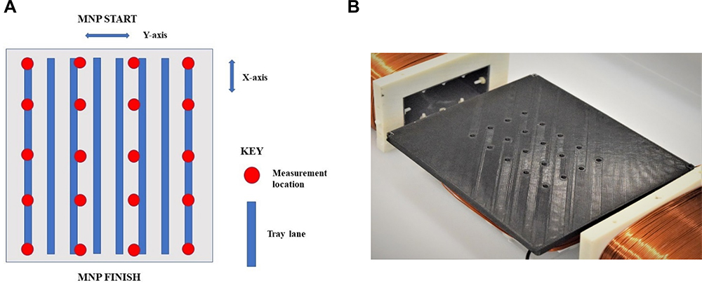 |
Figure 2 (A) Schematic for the magnetic field measurements. (B) Photograph of 3D-printed holder for the gauss meter probe. |
MNP Synthesis and Preparation
Five different types of MNPs were used in these studies, including graphene-coated cobalt MNPs (TurboBeads™-Carboxy, TurboBeads GMBH, Zurich, Switzerland),29 nickel nanorods (NiNRs), gold-iron alloy MNPs (Fe0.5Au0.5 MNPs),25 gold-coated Fe3O4@Au MNPs,5 and uncoated Fe3O4 MNPs.5 MNP characteristics are given in Table 1. MNP compositions and sizes varied considerably, as seen in Table 1. TurboBeads were purchased commercially and used without modification. NiNRs were provided by Weinberg Medical Physics, Inc. The synthesis details for NiNRs – which are Au-Ni-Au rods created via template-guided electroplating – have been previously reported.30–32 Fe0.5Au0.5 alloy MNPs with streptavidin surface coatings were supplied by IMRA America, Inc. (Ann Arbor, Michigan, USA).25 Gold-coated Fe3O4@Au MNPs and uncoated Fe3O4 MNPs were synthesized in our laboratory as previously described.5 TurboBeads™ and NiNRs were ferromagnetic, while the other MNPs were paramagnetic.
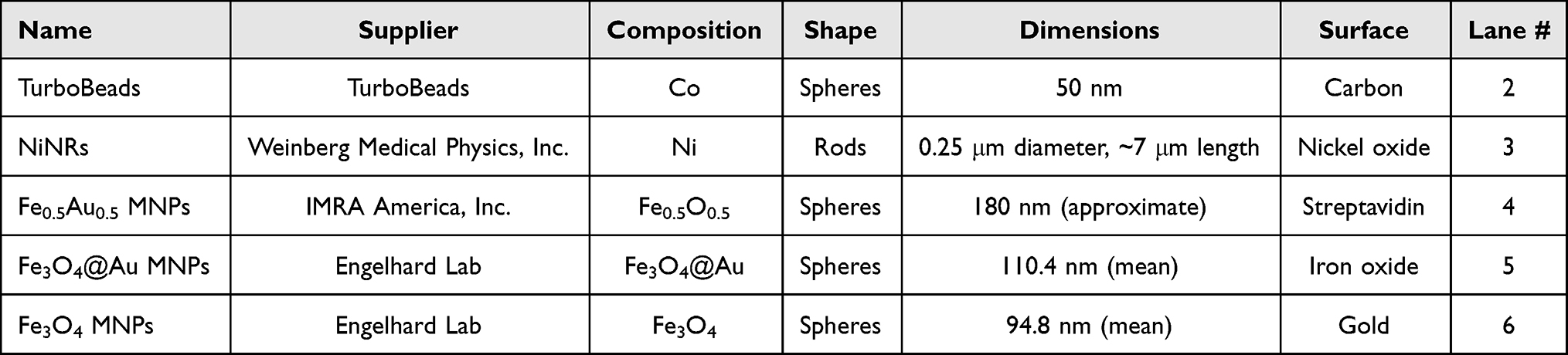 |
Table 1 Description of MNPs Tested |
In preparation for velocity determinations, all MNPs were sonicated, vortexed, rinsed with phosphate-buffered saline (PBS), then resuspended in 0.5 mL PBS. Each tray lane (or channel) to be used for testing was filled with 2 mL of artificial cerebrospinal fluid (aCSF, Harvard Apparatus, Holliston, MA). One hundred microliters of each MNP suspension was then pipetted into their respective lane. A neodymium iron boron permanent magnet was used to magnetize and collect the MNPs at one end of the lanes (i.e., the start position or origin). The permanent magnet was then removed, the rotating magnetic field was activated, and the translational motion of the MNPs was observed and recorded.
MNP Velocity Determinations and Lane Calibration/Normalization
Video recordings of the motion of MNP agglomerates in response to the MMS were collected with a camera (Kodak PixPro Friendly Zoom, model FZ53-RD, 16 MP, Eastman Kodak Co., Rochester, NY) positioned 135 cm above the acrylic tray. Images were recorded at 30 frames per second. MNP velocities (in cm/s) were determined by direct analysis of video recordings, by averaging the time it took for the leading edge of each MNP cluster to traverse the length of the 10.5 cm tray lane (n ≥ 3). For rotational frequency determinations, MNPs were exposed to rotating fields ranging from 5 Hz to 200 Hz.
Given the possibility of small variations in the composition (i.e., roughness) of the milled acrylic tray lanes, and the slight nonuniformity of the rotating magnetic field, the system was calibrated prior to the collection of experimental data. This was done by placing a single type of MNP (TurboBeads™) into each of the eight tray lanes, activating the MMS, and recording MNP motion down all eight lanes. The purpose of the calibration was to determine if there was any possible “lane effect” on the MNP velocity determinations. TurboBead™ velocity was averaged for six transits of the length of the channels, in the eight lanes simultaneously. The relative mean velocity (in cm/s) for each lane was therefore established.
A non-dimensional calibration factor Clane# was calculated by dividing the lane velocity from these control determinations by the means from these determinations. For lanes in which the control determination yielded velocities higher than the control mean of the means, Clane# > 1. For lanes in which the control determination yielded velocities lower than the mean of the means, Clane# < 1. Experimental test data (velocity in cm/s) of the various MNPs in the individual lanes were divided by the lane-specific calibration factor Clane# to generate the normalized velocity for that MNP according to the specific lane. This calibration and normalization process assured that individual lane variations due to tray construction or magnetic field strength did not affect MNP testing. Recalculation of the Clane# values was necessary if a different tray was used in the MMS, given the fact that the trays were not microscopically identical.
MNP Delivery of Doxorubicin Hydrochloride (Dox)
In accordance with the overarching purpose of this study, the experimental data were used to choose one of the five types of MNPs for further testing. For these experiments, the tray lanes were filled with 1 mL of artificial cerebrospinal fluid (aCSF). A 3D printed stopper was placed 0.8 cm (the same as the diameter of 1 well of a 96 well plate) from the start of the lane, and 50 µL of 2 mg/mL Dox was loaded into the confined area. This corresponds to well E2 on a 96 well plate. The tray was carefully placed into a CLARIOstar Plus microplate reader (BMG Labtech, Cary NC) and the “pre-run” emission spectrum for the drug was obtained. The tray was then placed on top of the z-coil in the MMS, the enclosed starting point was loaded with 50 µL of sonicated and vortexed NiNRs, and the rotating magnetic field was generated using a frequency of 15 Hz and voltage of 18 Vpp. These settings were used to ensure that z-coil shaking was not a factor in dispersing drug along the lane. Once NiNRs were collected at the other end of the lane, another stopper was placed 0.8 cm from the end point (to avoid drug or MNPs from diffusing backwards) which corresponds to well E12 on a 96 well plate. The tray was then inserted back into the microplate reader and the “post-run” emission spectrum was obtained. A control lane of the tray was studied in the same manner with NiNRs but without any Dox. Care must be taken in designing these experiments, since the presence of MNPs may interfere with drug fluorescence.
Results
MMS Field Strength Determinations and Tray Calibration Testing
To test the uniformity of the magnetic field produced by the MMS, the acrylic tray was replaced with the probe holder, and the maximum field strength was determined using the gauss meter for each of the 20 positions. Results are shown in Figure 3A. The strength of the rotating magnetic field generated across the acrylic tray by the MMS was found to be uniform. The maximal magnetic field strength readings were found to range from 2.5 to 3.2 mT across the locations of the tray lanes, as indicated.
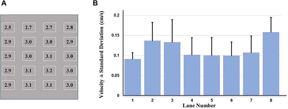 |
Figure 3 (A) Results of the magnetic field testing, with the maximal magnetic field values in milli Tesla (mT) shown for each probe location. (B) Bar graph of the calibration velocities for the eight lanes, with testing performed at 20 Hz, using TurboBeads™. |
Since variations in the measured velocities of the MNPs could potentially result from differences in the strength or angle of the magnetic field along the individual lanes, or to slight differences in the smoothness or texture of the floors of the lanes, the MMS was calibrated prior to more detailed experiments. For the calibration studies, TurboBeads™ were placed into each of the eight lanes of the acrylic tray. Results are shown in Figure 3B. The greatest difference between adjacent lanes was seen for lanes 7 and 8. Lanes 2–6 were chosen for subsequent MNP testing, and lane calibration factors (Clane#) were used for data normalization.
MNP Velocities in Relation to Frequency of the Rotating Magnetic Field
To determine the effect of rotating field frequency on the velocities of the five types of MNPs selected for testing here, MNP velocities were simultaneously determined at frequencies ranging from 5 Hz to 200 Hz, in repetitive experiments utilizing the different frequencies. The schematic for these experiments is shown in Figure 4A–C. Panel A shows the overall design of the MMS, with the acrylic tray positioned on the z-coil within the two x-coils. Panel B indicates how the different types of MNPs are raced against each other down the lanes of the tray. Panel C illustrates how the rotating electromagnetic field causes the chains or clusters of MNPs to rotate and walk along the surfaces of the lanes. Three velocity measurements were taken at each frequency (i.e., n=3).
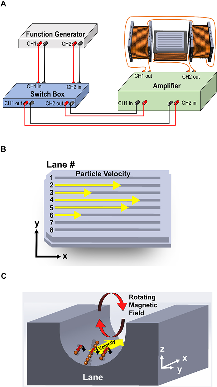 |
Figure 4 Schematic of the MMS system and principles underlying the experiments presented here. (A) Electric components, coils, and acrylic tray. (B) Acrylic tray illustration with numbered lanes and direction of MNP movement. (C) Depiction of chains of MNPs rotating near the floor of a lane. |
The frequency-velocity plots for the five different MNPs are shown in Figure 5. For frequencies greater than 20 Hz, the clusters of TurboBeads™ moved appreciably faster than all other tested MNPs, with a peak velocity of 0.9 cm/s. TurboBeads™ and NiNRs displayed a similar velocity at 20 Hz. All MNPs were found to encounter a “critical” frequency between 20 Hz and 30 Hz, at which point velocity decreased with any additional increase in rotational field frequency. NiNRs and TurboBeads™ continued to travel down the tray lane at frequencies up to 150 Hz and 200 Hz, respectively. The iron-based MNPs tested here did not have appreciable velocities above 60 Hz. These data indicate the tuneable nature of the MMS, and the variation in MNP responses. The rotational frequency of the MMS system can be adjusted to optimize the velocity for a given type of MNP. Here, different types of MNPs were tested in aCSF, but the system can also be used to compare different modifications of a single type of MNP, or the velocity of a particular MNP through different media (e.g., blood, urine, lymph, or cerebrospinal fluid) or media varying in a given characteristic (e.g., viscosity, osmolarity, protein content).
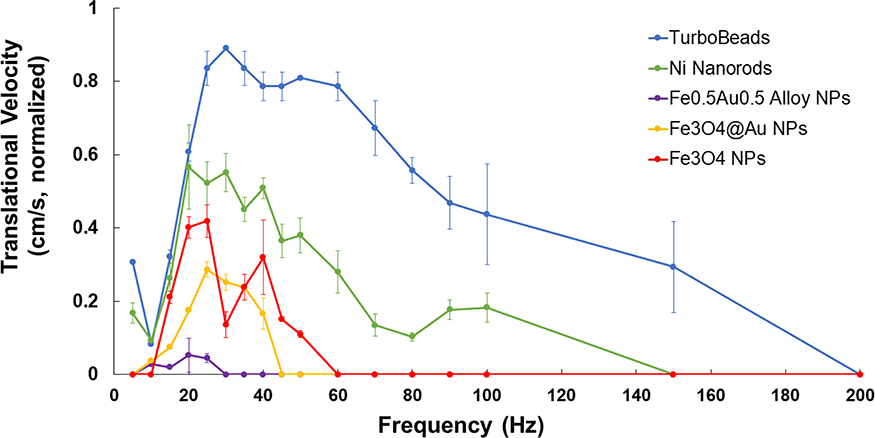 |
Figure 5 Translational velocities for the five MNPs, plotted as a function of magnetic field frequency (Hz). All MNPs experienced a critical frequency between 20 Hz and 30 Hz, after which point velocity decreased with further increases in rotational frequency. NiNRs and TurboBeads continued to travel down the tray lanes at frequencies up to 150 Hz and 200 Hz, respectively. The iron based MNPs tested here did not have appreciable velocities above 60 Hz. These data indicate the tuneable nature of the MMS, and the variation in MNP responses. |
MNP Velocities in Relation to Increasing Height Above the z-Coil
Further experiments were performed to determine whether or not the velocity of the MNPs could be maintained despite increasing the height of the tray, ie moving it further away from the z-coil. This is an important consideration for any instrument intended to have a clinical use for moving MNPs within the human body. The height of the tray above the z-coil array was therefore increased from 0 cm to 18 cm, in 1.5 cm increments. The illustration of how this experiment was performed is shown in Figure 6A. The frequency of 20 Hz (at which all the MNPs move) was chosen for these experiments. Figure 6B shows the resulting data, namely the velocity plots of all five MNPs according to their height above the z-coil. The data indicated that NiNRs are far more responsive at an increased height, even up to 16.5 cm from the z-coil. The NiNRs were able to move with a maximal velocity of 1.2 cm/s at a height of 6.5 cm above the z-coil. Interestingly, TurboBeads™ demonstrated almost no change in velocity with varying distance from the MMS coil array at this frequency, while the iron-based MNPs tested here did not display movement at distances >11.5 cm above the z-coil.
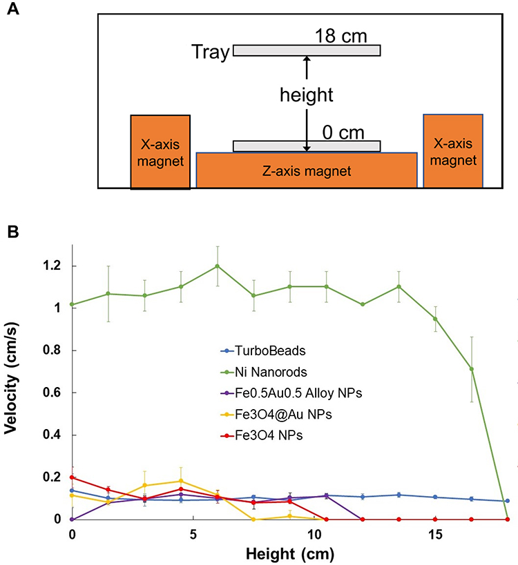 |
Figure 6 Effect of tray height on MNP velocity. (A) Diagram illustrating the progressive changes in tray position with respect to the MMS coils. (B) Normalized translational velocities for the five MNPs, plotted as a function of tray height above the z-axis magnet. NiNRs were found to have the preferred response and were selected for further testing with Dox. |
Linear Drug Dispersion Using NiNRs
Based on the data above, NiNRs were chosen as the MNPs used for additional studies of the MMS, for evaluating the potential of the system for assessing MNP-directed drug dispersion or delivery. Since changes in the media or “milieu” of MNPs can change their properties, including their translational velocities,21 the velocities of NiNRs were studied with and without the addition of Dox. Dox addition was found to have no appreciable effect on the velocity of NiNRs in aCSF (15 Hz, 18 Vpp), as shown in Figure 7A.
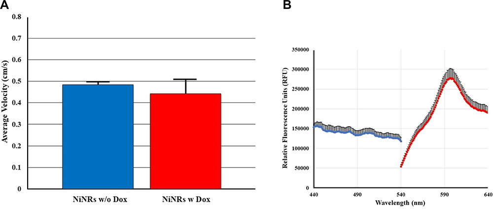 |
Figure 7 (A) Velocity comparison of NiNRs with (w) and without (w/o) Dox, n=3. MMS settings of 15 Hz and voltage of 18 Vpp were used. The addition of Dox did not change the velocity of NiNRs. (B) Excitation and emission spectra of Dox, n=3. The blue points (left) indicate excitation, and the red points (right) indicate emission. |
To quantify the dispersion of Dox by NiNRs along the lanes of the tray, fluorescence spectroscopy was used, with placement of the tray into the CLARIOstar Plus microplate reader before and after translational movement of NiNRs by the MMS. The standard emission spectrum of Dox shows a peak at 596 nm (as seen in Figure 7B), and this was used as the wavelength for quantifying the presence of Dox along the lanes of the tray. Drug fluorescence and the lane set-up prior to a representative run is shown in Figure 8A and C. Drug fluorescence and dispersion after a 30 sec run is shown in Panels B and D. The plate reader was more sensitive than the naked eye, in detecting Dox. The bar graphs show the fluorescence in RFU (y-axis) vs tray distance (x-axis). The “pre-run” data show Dox fluorescence confined to the first 0.8 cm of the tray lane, thus producing a peak which would correspond to one well of a 96 well plate. The “post run” data indicate how Dox was quickly dispersed along the 10.5 cm length of the acrylic tray with fluorescence at every 0.8 cm increment. This is much faster than the speed of simple drug diffusion, unenhanced by the addition of MNPs.5 The rotating magnetic field of the MMS can therefore be used to convey a drug (here, Dox) down a conduit using an MNP carrier (demonstrated with NiNRs) without direct drug binding to the MNPs.
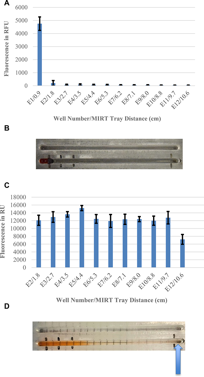 |
Figure 8 Demonstration of MNP-directed drug dispersion. (A) Pre-run Dox fluorescence at 596 nm (the peak emission wavelength). (B) Close up photograph of two tray lanes prior to the run (i.e., the pre-run lane set-up), with Dox at the starting position. (C) Post-run Dox fluorescence at 596 nm. (D) Close up photograph of two tray lanes after the magnetic run, showing Dox dispersion. The NiNRs have collected at the end of the lane, as indicated by the blue arrow. Abbreviation: MIRT, magnetically induced rotation and translation. |
Discussion
In this report, we describe the coil array, testing tray, particle imaging system, and data analysis methods used to simultaneously measure velocities of five different MNPs of widely varying dimensions and compositions, in response to a tuneable rotating electromagnetic field. TurboBeads™ and NiNRs were found to display similar velocities at the standard 15–25 Hz frequency range. NiNRs were found to move faster, however, when the acrylic tray was moved farther from the z-coil, which is advantageous. NiNRs were therefore chosen for additional studies, which demonstrated their successful use as agents for rapidly dispersing unbound Dox along a linear conduit. Dox has often been used in MNP studies, in bound form.33,34 TurboBeads™ and NiNRs both exhibit ferromagnetic ordering, retaining strong remnant magnetism even in the absence of an applied field from the coil array. The other MNPs exhibit paramagnetic behaviour, losing nearly all their remnant magnetism in the absence of an externally applied field. This may at least partially explain the optimization results, but since so many factors are at play (eg particle shape, chain and cluster formation, dipole interactions, zeta potential, corona formation), it is very useful to be able to perform practical side-by-side testing, as demonstrated here.
MNPs have been shown to be extremely valuable tools, with a wide variety of uses in engineering16,34,35 and medicine.1,36–38 They have been utilized as reusable catalysts,39,40 in situ diagnostic agents,41 contrast agents for magnetic resonance imaging,42 and for therapeutic hyperthermia14,16,21,43,44 – to name but a few noteworthy examples. In response to the application of a magnetic field, MNPs form chains then clusters which move at varying speeds depending on the magnetic properties of the particles, internal particle–particle interactions, particle–surface interactions, and magnetic field conditions.8,13 Manipulation of MNPs and other constructs using rotating magnetic fields has been shown to be useful in wide-ranging applications including moving non-magnetic objects,45,46 generating micro- and macroscopic flows,47 quantifying the viscosity of solutions,48 controlling the motion of individual cells,49–51 climbing vertical walls,52 translating against macroscopic fluid flows,53 rotating at kilohertz frequencies,51 determining the concentration of microbes in a solution,54–56 assisting in automated protein harvesting,46 dispersing microbial biofilms,57 destroying cells via magneto-mechanical lysosomal disruption,38 lysing blood clots,6 and killing cancer cells by conveying a cytotoxic agent.5,25
In the field of magnetically actuated micro-robotics, rotating magnetic field manipulation has been modelled extensively. Particle rotation breaks the plane of symmetry near a solid–liquid boundary, allowing for directed translation.47,52,58,60 Detailed modelling of particle chaining and rotation under such rotating magnetic field application has been performed.59–61 At the microscale, MNPs with magnetization  agglomerate and form three-dimensional chains due to the imposed magnetic field
  . These chains can then rotate due to torque
  , inducing one-dimensional translational motion. At low Reynolds number settings, a symmetry breaking dynamic is required to couple rotation and translation.62 While particles rotating far from a solid–liquid boundary surface will experience no translation due to a lack of symmetry breaking, rotation-translation coupling increases as rotating particles or particle chains approach a surface.19,63,64
Near a surface, segments of a particle chain move alternatingly closer to and farther from the solid–liquid boundary. As there is a no-slip condition at the solid–liquid boundary, particle chain segments rotating nearer to the surface experience more drag than chain segments rotating farther from the surface. As the chain rotates, alternating segments move into and out of higher and lower drag fluidic environments, symmetry is broken, and rotation-translation coupling occurs. For chains of spherical particles, Sing et al47 derived a simple relationship for one-dimensional translational velocity  as a function of rotation frequency
  , number of particles
  , particle radius
  , and height from the centre of the particle chain to the solid surface
  :
:

Equation 1 holds true for scenarios in which particle chain rotation is in phase with the applied rotating magnetic field. At the critical frequency  , the applied rotating magnetic field is insufficiently strong to keep the particle chain rotating in phase with the applied magnetic field. At this point, particle chain rotation frequency decouples from applied rotating field frequency and Equation 1 no longer holds. At and above
  , translational velocity
  slows. Heating does not occur with MNPs until much higher frequencies are used.65 While decreasing the magnetic field strength may operate as a proxy for distance, changes in the shape, gradient, and strength of the magnetic field all play an important role in how rotational MNP manipulation will operate at larger scales.
The concept of magnetic drug targeting is very appealing.1,5,6,12,25 The lack of specific targeting of drugs given systemically, especially chemotherapeutic agents, presents a significant disadvantage and contributes to drug toxicity.4,6,66 Rotational magnetic drug targeting offers a way to improve drug delivery through selected conduits, potentially increasing efficacy and reducing nonspecific effects.5,6,25 Results presented here are important because 1) they lend insight into the design of more sophisticated electromagnetic systems that will ultimately be used in the clinical setting, and 2) the ability to “race” MNPs in real time (and precisely study their motion) is useful as a factor (in addition to toxicity, for example) for determining which MNPs should be prime candidates for expensive animal studies and clinical trials. Models used for MNP testing can be scaled to animal or human dimensions, and made more sophisticated by replicating physiologic fluid composition and flow, body temperature, and surface characteristics of the conduit of interest.5,25
Here we take a macroscopic, centimetre-scale (“mesoscale”) approach, agnostic to particle chaining properties, focusing instead on the motion of the leading cluster of MNPs in each channel and how those clusters respond to varying field frequencies and distances from the MMS coil array. Our results are intended to introduce a method of assaying libraries of MNPs and their modifications to quantify translational velocities, and ability to disperse or deliver a therapeutic agent. Future implementation of the method can be used compare intrinsic variables such as MNP concentration, size distribution, surface functionalization, shape and/or margination.5,67 Additionally, the method allows for testing extrinsic factors such as variations in the surface material or texture of the conduit (eg vessel lumen versus implanted stent), composition of the transit media (such as blood, urine, lymph, or cerebrospinal fluid), and presence of proteins or floating cells.
Conclusion
Electromagnetic devices for generating rotating fields for manipulating MNPs at a distance warrant further study and design refinements so that they ultimately may be used in clinical trials. Parallel multichannel MNP testing is a useful technique, so that the translational velocities of MNPs which vary in composition can be directly compared, highlighting their potential for further in vivo applications.
Acknowledgments
The authors would like to acknowledge and thank Aleksandar Lazic (B.S. Mechanical Engineering, Illinois Institute of Technology) for assistance with 3D modelling of the probe holder tray, Fernando Borges and Marja Bittencout Pimentel of the Illinois Institute of Technology for technical expertise, and Rishi Singh (B.Arch. Illinois Institute of Technology) for assistance in 3D printing of the acrylic tray lane stoppers.
Disclosure
Dr Herbert H Engelhard reports grants from IMRA America, Inc., during the conduct of the study. The authors report no other conflicts of interest in this work.
References
1. Stueber DD, Villanova J, Aponte I, Xiao Z, Colvin VL. Magnetic nanoparticles in biology and medicine: past, present, and future trends. Pharmaceutics. 2021;13(7):943. doi:10.3390/pharmaceutics13070943
2. Li X, Li W, Wang M, Liao Z. Magnetic nanoparticles for cancer theranostics: advances and prospects. J Control Release. 2021;335:437–448. doi:10.1016/j.jconrel.2021.05.042
3. Dulińska-Litewka J, Łazarczyk A, Hałubiec P, Szafrański O, Karnas K, Karewicz A. Superparamagnetic iron oxide nanoparticles-current and prospective medical applications. Materials. 2019;12(4):E617. doi:10.3390/ma12040617
4. Alromi DA, Madani SY, Seifalian A. Emerging application of magnetic nanoparticles for diagnosis and treatment of cancer. Polymers. 2021;13(23):4146. doi:10.3390/polym13234146
5. Willis AJ, Pernal SP, Gaertner ZA, et al. Rotating magnetic nanoparticle clusters as microdevices for drug delivery. Int J Nanomed. 2020;15:4105–4123. doi:10.2147/IJN.S247985
6. Pernal SP, Willis AJ, Sabo ME, et al. An in vitro model system for evaluating remote magnetic nanoparticle movement and fibrinolysis. Int J Nanomed. 2020;15:1549–1568. doi:10.2147/IJN.S237395
7. Pouponneau P, Leroux JC, Martel S. Magnetic nanoparticles encapsulated into biodegradable microparticles steered with an upgraded magnetic resonance imaging system for tumor chemo-embolization. Biomaterials. 2009;30(31):6327–6332. doi:10.1016/j.biomaterials.2009.08.005
8. Anand M. Tailoring local hysteresis in small clusters of dipolar interacting magnetic nanoparticles. NANO. 2021;16(09):2150104. doi:10.1142/S1793292021501046
9. Hartwig V, Virgili G, Mattei FE, et al. Occupational exposure to electromagnetic fields in magnetic resonance environment: an update on regulation, exposure assessment techniques, health risk evaluation, and surveillance. Med Biol Eng Comput. 2022;60(2):297–320. doi:10.1007/s11517-021-02435-6
10. Cao Q, Han X, Li L. Configurations and control of magnetic fields for manipulating magnetic particles in microfluidic applications: magnet systems and manipulation mechanisms. Lab Chip. 2014;14(15):2762–2777. doi:10.1039/c4lc00367e
11. Nacev A, Komaee A, Sarwar A, et al. Towards control of magnetic fluids in patients. IEEE Control Systems Mag. 2012;6:33–74.
12. Shapiro B, Kulkarni S, Nacev A, Muro S, Stepanov PY, Weinberg IN. Open challenges in magnetic drug targeting. Wiley Interdiscip Rev Nanomed Nanobiotechnol. 2015;7(3):446–457. doi:10.1002/wnan.1311
13. Anand M. Hysteresis in a linear chain of magnetic nanoparticles. J Appl Phys. 2020;128(2):023903. doi:10.1063/5.0010217
14. Mille N, De Masi D, Faure S, Asensio JM, Chaudret B, Carrey J. Probing dynamics of nanoparticle chains formation during magnetic hyperthermia using time-dependent high-frequency hysteresis loops. Appl Phys Lett. 2021;119(2):022407. doi:10.1063/5.0056449
15. Anand M, Banerjee V, Carrey J. Relaxation in one-dimensional chains of interacting magnetic nanoparticles: analytical formula and kinetic Monte Carlo simulations. Phys Rev B. 2019;99(2):024402. doi:10.1103/PhysRevB.99.024402
16. Anand M. Thermal and dipolar interaction effect on the relaxation in a linear chain of magnetic nanoparticles. J Magn Magn Mater. 2021;522:167538. doi:10.1016/j.jmmm.2020.167538
17. Vuppu AK, Garcia AA, Hayes MA. Video microscopy of dynamically aggregated paramagnetic particle chains in an applied rotating magnetic field. Langmuir. 2003;19(21):8646–8653. doi:10.1021/la034195a
18. Rikken RSM, Nolte RJM, Maan JC, van Hest JCM, Wilson DA, Christianen PCM. Manipulation of micro- and nanostructure motion with magnetic fields. Soft Matter. 2014;10(9):1295–1308. doi:10.1039/c3sm52294f
19. Morimoto H, Ukai T, Nagaoka Y, Grobert N, Maekawa T. Tumbling motion of magnetic particles on a magnetic substrate induced by a rotational magnetic field. Phys Rev E Stat Nonlin Soft Matter Phys. 2008;78(2 Pt 1):021403. doi:10.1103/PhysRevE.78.021403
20. Kim JW, Jeong HK, Southard KM, Jun YW, Cheon J. Magnetic nanotweezers for interrogating biological processes in space and time. Acc Chem Res. 2018;51(4):839–849. doi:10.1021/acs.accounts.8b00004
21. Anand M, Carrey J, Banerjee V. Spin morphologies and heat dissipation in spherical assemblies of magnetic nanoparticles. Phys Rev B. 2016;94(9):094425. doi:10.1103/PhysRevB.94.094425
22. Platt M, Muthukrishnan G, Hancock WO, Williams ME. Millimeter scale alignment of magnetic nanoparticle functionalized microtubules in magnetic fields. J Am Chem Soc. 2005;127(45):15686–15687. doi:10.1021/ja055815s
23. Mair LO, Chowdhury S, Paredes-Juarez GA, et al. Magnetically aligned nanorods in alginate capsules (MANIACS): soft matter tumbling robots for manipulation and drug delivery. Micromachines. 2019;10(4):E230. doi:10.3390/mi10040230
24. Ali J, Cheang UK, Liu Y, et al. Fabrication and magnetic control of alginate-based rolling microrobots. AIP Adv. 2016;6(12):125205. doi:10.1063/1.4971277
25. Engelhard HH, Willis AJ, Hussain SI, et al. Etoposide-bound magnetic nanoparticles designed for remote targeting of cancer cells disseminated within cerebrospinal fluid pathways. Front Neurol. 2020;11:596632. doi:10.3389/fneur.2020.596632
26. Shamsi M, Sedaghatkish A, Dejam M, Saghafian M, Mohammadi M, Sanati-Nezhad A. Magnetically assisted intraperitoneal drug delivery for cancer chemotherapy. Drug Deliv. 2018;25(1):846–861. doi:10.1080/10717544.2018.1455764
27. Mair LO, Adam G, Chowdhury S, et al. Soft capsule magnetic millirobots for region-specific drug delivery in the central nervous system. Front Robot AI. 2021;8:702566. doi:10.3389/frobt.2021.702566
28. Engelhard HH, Pernal SP, Gaertner ZA, et al. A novel tissue culture tray for the study of magnetically induced rotation and translation of iron oxide nanoparticles. IEEE Magn Lett. 2017;8:1–5. doi:10.1109/LMAG.2017.2761818
29. Grass RN, Athanassiou EK, Stark WJ. Covalently functionalized cobalt nanoparticles as a platform for magnetic separations in organic synthesis. Angew Chem Int Ed. 2007;46:4909–4912. doi:10.1002/anie.200700613
30. Mair LO, Superfine R. Single particle tracking reveals biphasic transport during nanorod magnetophoresis through extracellular matrix. Soft Matter. 2014;10(23):4118–4125. doi:10.1039/c4sm00611a
31. Mair LO, Weinberg IN, Nacev A, et al. Analysis of driven nanorod transport through a biopolymer matrix. J Magn Magn Mater. 2015;380:295–298. doi:10.1016/j.jmmm.2014.09.059
32. Jafari S, Mair LO, Weinberg IN, et al. Magnetic drilling enhances intra-nasal transport of particles into rodent brain. J Magn Magn Mater. 2019;469:302–305. doi:10.1016/j.jmmm.2018.08.048
33. Ramnandan D, Mokhosi S, Daniels A, Singh M. Chitosan, polyethylene glycol and polyvinyl alcohol modified mgfe2o4 ferrite magnetic nanoparticles in doxorubicin delivery: a comparative study in vitro. Molecules. 2021;26(13):3893. doi:10.3390/molecules26133893
34. Lee H, Kim DI, Kwon SH, Park S. Magnetically actuated drug delivery helical microrobot with magnetic nanoparticle retrieval ability. ACS Appl Mater Interfaces. 2021;13(17):19633–19647. doi:10.1021/acsami.1c01742
35. Choi K-H, Shokouhimehr M, Sung Y-E. Heterogeneous Suzuki cross-coupling reaction catalyzed by magnetically recyclable nanocatalyst. Bull Korean Chem Soc. 2013;34(5):1477–1480. doi:10.5012/BKCS.2013.34.5.1477
36. Chau NTT, Koh ES, Lee SJ, Rui Z, Yang SY. Functional polyelectrolyte coatings on polymeric and magnetic colloidal particles for antifouling and non-toxic bioconjugate nanoparticles. Macromol Res. 2021;29(12):843–846. doi:10.1007/s13233-021-9102-8
37. Wu K, Su D, Liu J, Saha R, Wang JP. Magnetic nanoparticles in nanomedicine: a review of recent advances. Nanotechnology. 2019;30(50):502003. doi:10.1088/1361-6528/ab4241
38. Lopez S, Hallali N, Lalatonne Y, et al. Magneto-mechanical destruction of cancer-associated fibroblasts using ultra-small iron oxide nanoparticles and low frequency rotating magnetic fields. Nanoscale Adv. 2022;4(2):421–436. doi:10.1039/D1NA00474C
39. Bakhtiarzadeh Z, Rouhani S, Karimi Z, et al. Hydrothermal self - sacrificing growth of polymorphous MnO2 on magnetic porous - carbon (Fe3O4@Cg/MnO2): a sustainable nanostructured catalyst for activation of molecular oxygen. Mol Catal. 2021;509:111603. doi:10.1016/j.mcat.2021.111603
40. Nourmohammadi M, Rouhani S, Azizi S, et al. Magnetic nanocomposite of crosslinked chitosan with 4,6-diacetylresorcinol for gold immobilization (Fe3O4@CS/DAR-Au) as a catalyst for an efficient one-pot synthesis of propargylamine. Mater Today Commun. 2021;29:102798. doi:10.1016/j.mtcomm.2021.102798
41. Onishi T, Mihara K, Matsuda S, et al. Application of magnetic nanoparticles for rapid detection and in situ diagnosis in clinical oncology. Cancers. 2022;14(2):364. doi:10.3390/cancers14020364
42. Farinha P, Coelho JMP, Reis CP, Gaspar MM. A comprehensive updated review on magnetic nanoparticles in diagnostics. Nanomaterials. 2021;11(12):3432. doi:10.3390/nano11123432
43. Gavilán H, Avugadda SK, Fernández-Cabada T, et al. Magnetic nanoparticles and clusters for magnetic hyperthermia: optimizing their heat performance and developing combinatorial therapies to tackle cancer. Chem Soc Rev. 2021;50(20):11614–11667. doi:10.1039/d1cs00427a
44. Fatima H, Charinpanitkul T, Kim KS. Fundamentals to apply magnetic nanoparticles for hyperthermia therapy. Nanomaterials. 2021;11(5):1203. doi:10.3390/nano11051203
45. Petit T, Zhang L, Peyer KE, Kratochvil BE, Nelson BJ. Selective trapping and manipulation of microscale objects using mobile microvortices. Nano Lett. 2012;12(1):156–160. doi:10.1021/nl2032487
46. Tung HW, Sargent DF, Nelson BJ. Protein crystal harvesting using the RodBot: a wireless mobile microrobot. J Appl Crystallogr. 2014;47:692–700. doi:10.1107/S1600576714004403
47. Sing CE, Schmid L, Schneider MF, Franke T, Alexander-Katz A. Controlled surface-induced flows from the motion of self-assembled colloidal walkers. Proc Natl Acad Sci U S A. 2010;107(2):535–540. doi:10.1073/pnas.0906489107
48. Tokarev A, Aprelev A, Zakharov MN, Korneva G, Gogotsi Y, Kornev KG. Multifunctional magnetic rotator for micro and nanorheological studies. Rev Sci Instrum. 2012;83(6):065110. doi:10.1063/1.4729795
49. Zhao Y, Zeng H. Rotational maneuver of ferromagnetic nanowires for cell manipulation. IEEE Trans Nanobioscience. 2009;8(3):226–236. doi:10.1109/TNB.2009.2025131
50. Elbez R, McNaughton BH, Patel L, Pienta KJ, Kopelman R. Nanoparticle induced cell magneto-rotation: monitoring morphology, stress and drug sensitivity of a suspended single cancer cell. PLoS One. 2011;6(12):e28475. doi:10.1371/journal.pone.0028475
51. Mair LO, Evans BA, Nacev A, et al. Magnetic microkayaks: propulsion of microrods processing near a surface by kilohertz frequency, rotating magnetic fields. Nanoscale. 2017;9:3375–3381. doi:10.1039/C6NR09459G
52. Zhang L, Petit T, Lu Y, et al. Controlled propulsion and cargo transport of rotating nickel nanowires near a patterned solid surface. ACS Nano. 2010;4(10):6228–6234. doi:10.1021/nn101861n
53. Karle M, Wöhrle J, Miwa J, et al. Controlled counter-flow motion of magnetic bead chains rolling along microchannels. Microfluid Nanofluidics. 2010;10:935–939. doi:10.1007/s10404-010-0727-8
54. McNaughton BH, Agayan RR, Clarke R, et al. Single bacterial cell detection with nonlinear rotational frequency shifts of driven magnetic microspheres. Appl Phys Lett. 2007;91:224105. doi:10.1063/1.2817593
55. Kinnunen P, Sinn I, McNaughton BH, et al. High frequency asynchronous magnetic bead rotation for improved biosensors. Appl Phys Lett. 2010;97:223701. doi:10.1063/1.3505492
56. Hecht A, Kinnunen P, McNaughton B, Kopelman R. Label-acquired magnetorotation for biosensing: an asynchronous rotation assay. J Magn Magn Mater. 2011;323(3–4):272–278. doi:10.1016/j.jmmm.2010.09.014
57. Mair LO, Nacev A, Hilaman R, et al. Biofilm disruption with rotating microrods enhances antimicrobial efficacy. J Magn Magn Mater. 2017;427:81–84. doi:10.1016/j.jmmm.2016.10.100
58. Tierno P, Golestanian R, Pagonabarraga I, et al. Controlled swimming in confined fluids of magnetically actuated colloidal rotors. Phys Rev Lett. 2008;101:218304. doi:10.1103/PhysRevLett.101.218304
59. Cēbers A, Javaitis I. Dynamics of a flexible magnetic chain in a rotating magnetic field. Phys Rev E Stat Nonlin Soft Matter Phys. 2004;69(2 Pt 1):021404. doi:10.1103/PhysRevE.69.021404
60. Biswal SL, Gast AP. Rotational dynamics of semiflexible paramagnetic particle chains. Phys Rev E Stat Nonlin Soft Matter Phys. 2004;69(4 Pt 1):041406. doi:10.1103/PhysRevE.69.041406
61. Gao Y, Hulsen MA, Kang TG, den Toonder JMJ. Numerical and experimental study of a rotating magnetic particle chain in a viscous fluid. Phys Rev E Stat Nonlin Soft Matter Phys. 2012;86(4 Pt 1):041503. doi:10.1103/PhysRevE.86.041503
62. Purcell EM. Life at low Reynolds number. Am J Phys. 1977;45:3–11. doi:10.1119/1.10903
63. Goldman AJ, Cox RG, Brenner H. Slow viscous motion of a sphere parallel to a plane wall i: motion through a quiescent fluid. Chem Eng Sci. 1967;22:637–651. doi:10.1016/0009-2509(67)80047-2
64. Reichert M, Stark H. Hydrodynamic coupling of two rotating spheres trapped in harmonic potentials. Phys Rev E. 2004;69:031407. doi:10.1103/PhysRevE.69.031407
65. Deatsch AE, Evans BA. Heating efficiency in magnetic nanoparticle hyperthermia. J Magn Magn Mater. 2014;354:163–172. doi:10.1016/j.jmmm.2013.11.006
66. Schirrmacher V. From chemotherapy to biological therapy: a review of novel concepts to reduce the side effects of systemic cancer treatment (Review). Int J Oncol. 2019;54(2):407–419. doi:10.3892/ijo.2018.4661
67. Carboni E, Tschudi K, Nam J, Lu X, Ma AWK. Particle margination and its implications on intravenous anticancer drug delivery. AAPS PharmSciTech. 2014;15(3):762–771. doi:10.1208/s12249-014-0099-6
 © 2022 The Author(s). This work is published and licensed by Dove Medical Press Limited. The
full terms of this license are available at https://www.dovepress.com/terms
and incorporate the Creative Commons Attribution
- Non Commercial (unported, 3.0) License.
By accessing the work you hereby accept the Terms. Non-commercial uses of the work are permitted
without any further permission from Dove Medical Press Limited, provided the work is properly
attributed. For permission for commercial use of this work, please see paragraphs 4.2 and 5 of our Terms.
© 2022 The Author(s). This work is published and licensed by Dove Medical Press Limited. The
full terms of this license are available at https://www.dovepress.com/terms
and incorporate the Creative Commons Attribution
- Non Commercial (unported, 3.0) License.
By accessing the work you hereby accept the Terms. Non-commercial uses of the work are permitted
without any further permission from Dove Medical Press Limited, provided the work is properly
attributed. For permission for commercial use of this work, please see paragraphs 4.2 and 5 of our Terms.