Back to Journals » Medical Devices: Evidence and Research » Volume 12
NITINOL-based actuator for device control even in high-field MRI environment
Authors Kalmar M ![]() , Boese A
, Boese A ![]() , Maldonado I, Landes R
, Maldonado I, Landes R ![]() , Friebe M
, Friebe M ![]()
Received 9 April 2019
Accepted for publication 28 June 2019
Published 19 August 2019 Volume 2019:12 Pages 285—296
DOI https://doi.org/10.2147/MDER.S211686
Checked for plagiarism Yes
Review by Single anonymous peer review
Peer reviewer comments 2
Editor who approved publication: Dr Scott Fraser
Marco Kalmar, Axel Boese, Ivan Maldonado, Rainer Landes, Michael Friebe
Intelligente Katheter Inka, Otto-von-Guericke University Magdeburg, Magdeburg, Germany
Correspondence: Marco Kalmar Otto-von-Guericke-University, Universitaetsplatz 2, Magdeburg 39106, Germany
Tel +49 391 675 7025
Email [email protected]
Background: The magnetic resonance imaging (MRI) environment with its high-strength magnetic fields requires specialized and sometimes sophisticated solutions for otherwise simple problems. One of these problems is MR-compatible actuator mechanisms that transfer a signal into an action.
Purpose: Normal actuators are based on a magnetic effect (eg, relays) and will typically not work in magnetic fields exceeding 1000 G, eg, inside the bore of an MR scanner. To enable the use of clinical devices inside the MRI, eg, for interventional procedures, there is a need for fully compatible actuators.
Patients and methods: Various actuators were compared for the purpose as a simple on-off switch within an MRI. NITNOL wire as an actuator showed the highest potential because of its simplicity and reliability. We tested the possible force achieved by the NITINOL wire related to the respective energy consumption, to provide a travel range of 2 mm.
Results: Compared to other actuators, the NITNOL wire is cheaper and requires less space. In the switching process however, there is a delay due to the time required for the heating of the wire up to the transformation temperature. The NITINOL switch shows a reliable behavior with regard to the generated force and the switching path over the entire measurement. Significant artifacts, caused by the NITNOL wire could not be detected in the MRI.
Conclusion: NITINOL wires can be repeatedly used, are relatively easy to implement and could be an economic alternative to other more complicated actuator technologies.
Keywords: interventional MRI, MRI compatible, high-field magnet, actuator, injector
Introduction
Due to the strong and changing magnetic fields, normal clinical equipment, that is standard in other imaging modalities like computed tomography (CT) or X-ray, cannot be used inside an magnetic resonance imaging (MRI) cabin. Everything has to be built to operate reliably and prevent the associated dangers of working in strong magnetic fields specially for systems that are operating close to or directly inside the MR bore where the highest magnetic field strengths occur.1,2 For several MR imaging and therapeutic procedure protocols, additional assistance systems are necessary (eg, contrast agent injector).3,4 However, the main problem with respect to an actuator is that most of the devices that exist on the market contain magnetic components.5 With that they could pose a danger to the patient or staff and,6,7 on the other hand, their switching mechanism can be influenced by the magnetic field of the scanner.8 There are already a few different types of MRI-compatible actuator mechanisms available on the market,9 but these still have problems with repeatability, reliability, size, generated image artifacts or traceability.1 We designed and tested a new MRI-compatible actuator for a 3T MRI to enable proximal and inside bore activation of devices. This can achieved by transfering an electrical signal to a mechanical movement based on a NITINOL wire switch mechanism. The goal was not to develop a new engine drive, but to present a method to alternate between two switching states with the goal to reduce the size, costs and the required activation energy to a minimum.
Materials and methods
Actuator principles
An actuator mechanism can be realized based on a controllable movement that provides at least a minimum force. Possible actuator principles and their use in the MRI environment are listed in Table 1. All listed electrical actuators have the potential for use in “close to bore” MRI applications.10 Single piezo actuators are limited by a small travel range (µm to mm distances) and the high voltage (up to 15 V) that are needed for activation.11 There is the possibility of stacking the piezo actuators, however, to achieve a longer travel range, but the travel range with respect to the installation space of the actuator remains very small.12
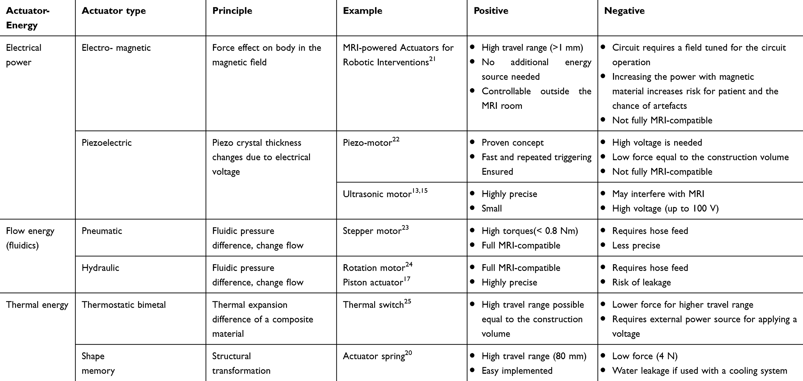 |
Table 1 Actuators and the rating for use in an MRI |
Ultrasonic motors (USMs) work via piezoelectric material in the stator. The generated traveling waves move the rotor by frictional forces.13 USMs look promising, as they are very small and have precise control, considering their high torque/size ratio a short reaction time. Another advantage is that the engine stops immediately when the power is switched off.14 Disadvantages are that they may interfere with the MRI scanner, if the motor is close to the isocenter of the image,15 and a high voltage may be needed.13
Electromagnetic actuators are a possible option if long travel ranges (>1 mm) are needed. The force that the actuator is able to create depends on the weight of the magnetic material inside the actuator. The higher the weight, the higher the risk that the patient can be hurt by the actuator due to magnetic attraction forces.16
Hydraulic actuators are working very precise, but come with a risk of fluid leakage and they require a lot of physical space, which make them not the best option for clinical use.17 Pneumatic systems can be built fully MRI compatible, but are less precise and have a slow response time compared to the hydraulic systems.1 Both pneumatic and hydraulic actuators are working with flow energy. With that, they require supply lines in the form of tubes and additional switches to control.18,19
The thermal energy actuators show high potential for 3-T MRI applications. Compared to shape memory metal, the resulting force of a bimetallic actuator is lower for the same energy consumption because of two materials working against each other.
Shape memory materials such as nickel titanium (NITINOL) can be deformed and will return into their original shape when heated to the structural change temperature. If a NITINOL wire is deformed plastically by traction, its length increases while its diameter decreases. Heating up the wire with an energy source will result in a contraction to its original length and with that can create a mechanical force. Since NITINOL is non magnetic this characteristic can be used as an actuator principle for “close to bore” MRI applications.20
Actuator design guide
To design an actuator for an MRI application based on the shape memory effect of NITINOL wires, the behavior of the material has to be analyzed. The main actuator design parameters are the dimensions (cross-sectional area and length), the transformation temperature and subsequently the energy needed to achieve that transformation.
A mechanical force can be realized by a contraction of a prior stretched NITINOL wire. This force is proportional to the cross-sectional area of the wire.26
Based on Figure 1, the cross-sectional area can be selected for a given required force.
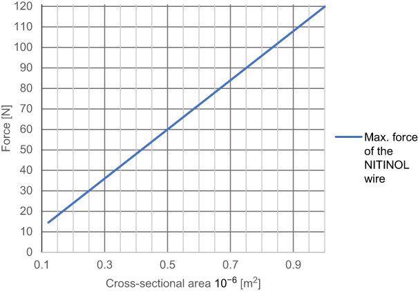 |
Figure 1 Resulting force depending on the cross-sectional area.27,28 |
The length of the wire depends on the required travel range. The maximal permissible plastic strain of NITINOL is about 5%.
(1)
The transformation temperature is the temperature at which the structural change in the phase of the shape memory material occurs. Depending on the nickel to titanium ratio, the transformation temperature changes.29
To reshape a NITINOL wire after deformation, heat energy has to be applied. Assuming a stable room temperature, the amount of energy  depends on the temperature difference
  and mass of the material
  .
.
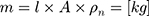
The (2) of the wire can be calculated over the
  , the cross-sectional area
 A and the density
  of the NITINOL wire.27

The energy needed to reach the deformation temperature is then calculated by multiplying the specific heat capacity of NITINOL c30 with the temperature difference (3) and the mass of the wire.


Figure 2 shows the energy needed to heat up different masses of NITINOL at a certain temperature.
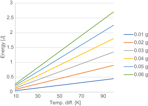 |
Figure 2 Needed energy to heat up the material NITINOL. |
This energy is the minimum energy needed to heat up the wire and can be provided by electrical energy. Like a resistor, the wire will heat up when electric current passes through.21


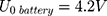
Based on the resistance of the NITINOL wire, the parameters of an electric energy source, eg, a battery, can be defined. The internal resistance of the battery is given by the no load voltage of the battery (5) and the short-circuit current
  .
.

The total resistance (6) is the amount of the internal resistance
  and the resistance of the wire
  .
.

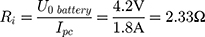
Using the operating voltage (7) of the battery and the total resistance
  , the operating current
  can now be calculated.

The energy (8) (9) supplied by the battery depends on the operating current
  , the operating voltage on the wire
  and the switching time
  needed to heat up the wire to the transformation temperature.

 This needs to be of course bigger than the minimum energy
  needed to heat up the wire.
If an actuator should be used several times, a certain capacity of the energy has to be provided. For “close to bore” MRI applications, MR conditional batteries are a required option. Based on a given capacity, it is possible to calculate the times the actuator can be used with a chosen battery.
(10)


This information allows a rough dimensioning of an actuator based on given requirements, which will now be demonstrated using a real example problem.
Actuator design example
Our example is based on the need for a mechanical switch to start the flow of an injection unit for contrast media application inside the MRI magnet bore. For that, an actuator travel range of 0.75 mm and a force of 15 N is needed. The actuator should be able to switch within 3 s. As energy source, a battery pack of 3 parallel lithium-ion batteries (3.7 V with 120 mAh/battery) was used (CP1654 A3 W, VARTA, Ellwangen, Germany). The no-load voltage of the battery pack was 4.2 V and the short-circuit current 1.8 A.
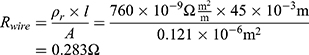
A NITINOL wire with a transformation temperature of 88°C was selected. To achieve the force of 15 N, the wire should have a cross-sectional area 0.121 mm2 (Figure 1) that leads to a wire diameter of 0.392 mm.
A wire length of 15 mm is calculated based on the 5% stretching and the travel range of 0.75 mm. To ensure proper functionality, a security factor 3 can be used. The resulting wire length is thereby 45 mm with a total travel range of 2.25 mm ( . According to Equations (2) and (3), the mass of the wire is:

Assuming a room temperature of 20°C and a deformation temperature of 88°C,  is
is  .
.
The energy needed to reach the deformation temperature can now be calculated to be

According to Equations (4)–(7), the total resistance  and the operating current
  , depending on the selected battery, can be estimated.
  is composed of the resistance of the wire
  and the internal resistance of the battery
  .
.
If the internal resistance of the battery is not given by the datasheet, it can be calculated with Equation (5).


With a switching time of  the used energy
  can be calculated with Equations (8) and (9).


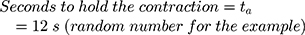
Knowing the operating current, it is now possible to calculate the number of times that the actuator can be used with one battery pack (Equation (10)).


Actuator design test
To validate the above calculations, a test setup of a NITINOL actuator (diameter 0.392 mm and length 45 mm) was created to determine the transformation energy, switching time, maximum force and the obtained travel range of the wire.
Assuming a plastic deformation of 5%, the expected travel range would be 2.25 mm. To avoid overstraining, the deformation was limited to 2 mm.
Measurement setup to evaluate switching time, travel range and transformation energy
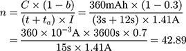
The plastically deformed wire ( ) was mounted into a measurement setup with a digital caliper (accuracy ±0.03 mm). One end was fixed, while the other end was left moveable (Figure 3A). Both ends were connected to an energy source (6225 A; PeakTech, Ahrensburg, Germany). The free wire length was 47 mm.
 |
Figure 3 Measurement setup to evaluate the required energy of the nitinol wire, the time to switch over and the travel range (A) and determining the force (B). |
For different voltages, the reaction time until wire contraction was measured. The earlier calculated optimum voltage  was chosen as the starting point. With no contraction observed after 10 s, the energy supply was interrupted for 5 mins to cool down the system. Knowing that the wire needs more power to contract, the measurement was subsequently repeated with an increased voltage in steps of 0.2 V. With contraction observed after less than 10 s, the experiment was repeated 5 times to average the measured switching time. The voltage was slowly increased step by step until it reached 1.7 V and the correlated switching time documented. Between measurements, the wire was stretched back.
Based on the measured time and the power supplied, the transformation energy could be calculated.
The travel range was measured using the ruler of the test setup.
Measurement setup for the maximum force of the NITINOL wire
To measure the force generated by wire deformation, the plastically deformed wire was attached to a Newton meter (FMI-200C2; ALLURIS, Freiburg, Germany) (Figure 3B). A voltage of 1.5 V was applied to the wire via the power supply (6225 A; PeakTech) until the transformation temperature was reached. While deforming to its original state, the wire generatesa force, which can be measured. This experiment was repeated six times. Between the measurements, the wire was stretched back and disconnected from the voltage supply for 5 mins to cool down.
Evaluation of the number of actuations and battery capacity
A lithium-ion battery CP1654 A3 W (VARTA) was chosen for the tests. According to the manufacturer, this battery is MRI compatible. The housing of this cell offers protection and it is lightweight (3.2 g). It theoretically offers a maximum short-circuit current of 0.6 A for 2 s.
For the evaluation, three lithium-ion batteries (4.2 V, 1.8 A) were connected in parallel to the NITINOL wire. Contraction was observed after 3 s and the energy supply interrupted after another 12 s to simulate holding time. The power consumption of this switching regime was measured using a digital multimeter 38XR-A (Beha-AMPROBE, Glottertal, Germany). After disconnection, the wire was cooled down for 5 mins and stretched again to 47 mm. This test was repeated five times. The measured power consumption allows to estimate the number of possible actuations using this battery pack.
MRI compatibility of the NITINOL switch with batteries
The NITINOL switch and batteries were checked for magnetic attraction toward the 3T MRI field. The measurement did not reveal a sizable attraction force.
All components of the NITINOL switch including the three lithium-ion batteries were enclosed in an acrylic glass box and observed while being brought into the MRI bore.
In a second measurement, it was verified that the switch causes no observable artifacts in the MRI image. For that, the switch and the batteries were attached to a phantom with adhesive tape (Figure 4) and the switch positioned in the isocenter of the MRI. A surface imaging coil was used (Spine 32) with an imaging area width of 450 mm and length of 140 mm. After moving the switch into the MRI (Figure 5), the radio frequency (RF) noise spectrum protocol provided by the MRI manufacturer was used to assess the effect. The resulting power density spectrum was reconstructed and reviewed for the presence of artifacts. This measurement was repeated for an activated and deactivated switch. After the MRI scan, the switch was again checked for functionality in order to ensure that the MRI did not cause any damage.
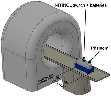 |
Figure 4 Measurement setup for NITINOL switch inside an MRI (NITINOL switch is outside). |
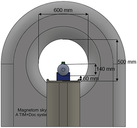 |
Figure 5 Measurement setup for NITINOL switch inside an MRI (NITINOL switch is inside). |
Results
Travel range
The travel range was measured during these experiments. When the transformation temperature was reached, the travel range of 2 mm was constant for the duration of the test.
Switching time and transformation energy
The measurement of the switching times is shown in Table 2. At the calculated voltage of 0.4 V, no contraction was observable after 10 s. Starting from 1.1 V, a contraction was observed. The corresponding heat-up time was approximately 7.7 s. To achieve a switching time of about 3 s, a voltage of 1.5 V has to be applied. Due to the nearly constant resistance of the system, a higher voltage leads to a higher current and to faster reaction of the NITINOL wire. Based on the measured voltage, current and time, the energy uptake was calculated.
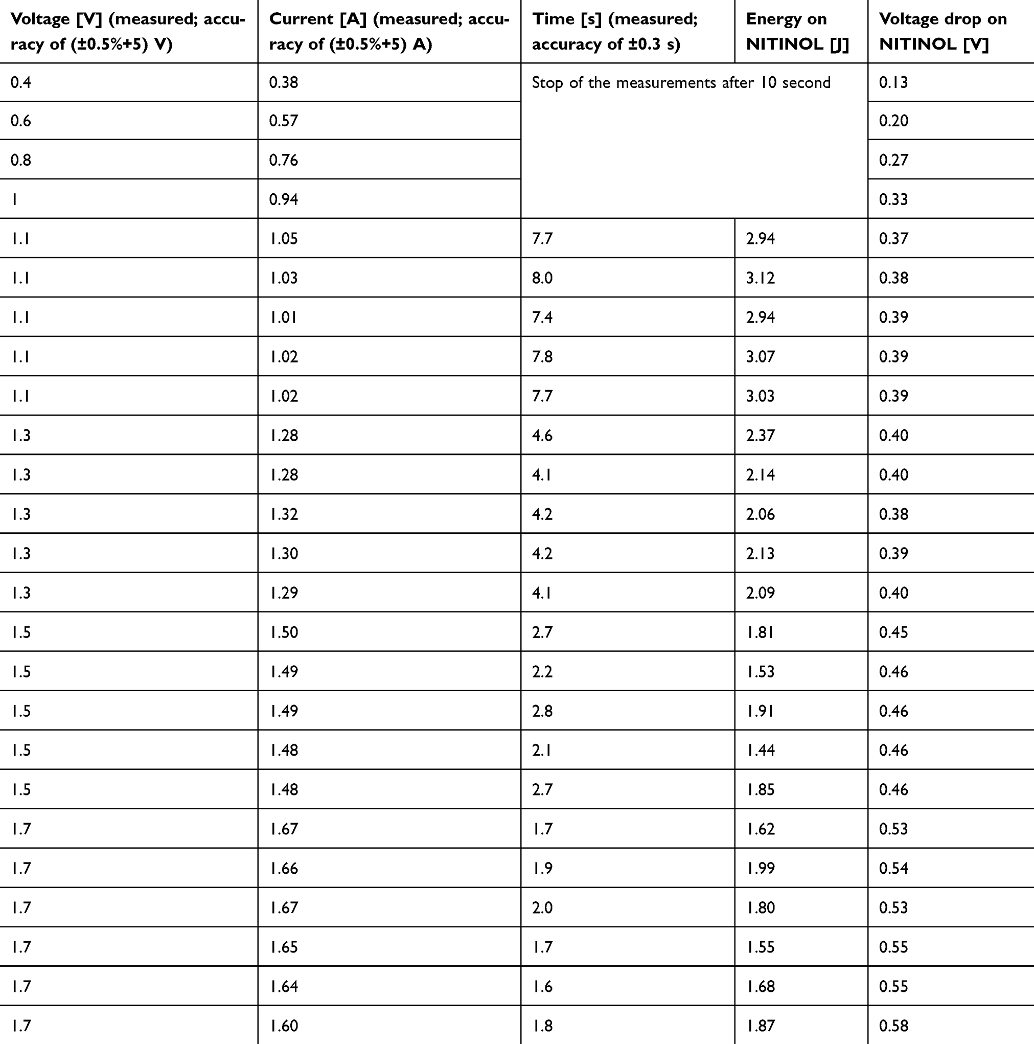 |
Table 2 Values of the switching time of the NITINOL wire (45 mm length and 0.392 mm diameter) at different voltages |
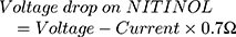
It turned out that the electrical wires leading to the NITINOL have a total resistance of  , which must be considered when determining the total energy consumed by the NITINOL actuator setup

Maximum force of the tested NITINOL wire
The results of the force measurements (accuracy of 0.05%) are displayed in Table 3. The average force achievable by the tested NITINOL wire was 14.56 N.
 |
Table 3 Force achieved directly with a 0.392 mm diameter NITINOL wire (l=45 mm) |
Number of actuations of the actuator
Based on the measured power consumption of the NITINOL-wire- battery-system the number of actuations the batteries can provide was calculated. Table 4 shows, that based on these results 46 theoretical cycles (safety parameter of 30%) are achievable.
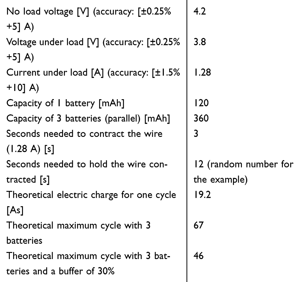 |
Table 4 Measurement of power consumption and the calculated cycles to actuate the NITINOL wire |
Discussion
The travel range of the NITINOL wire was constant, showing that even with frequent use of the switch, a reproducible return path is guaranteed. Figures 6 and 7 are showing an already MRI tested version of the NITINOL switch as the basis for starting an injection process remotely.
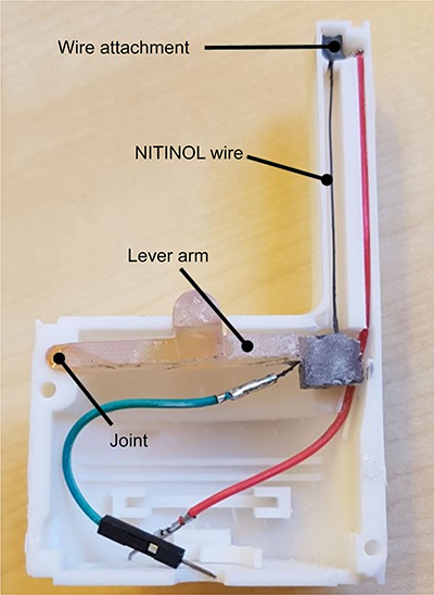 |
Figure 6 NITINOL switch with opened shell. |
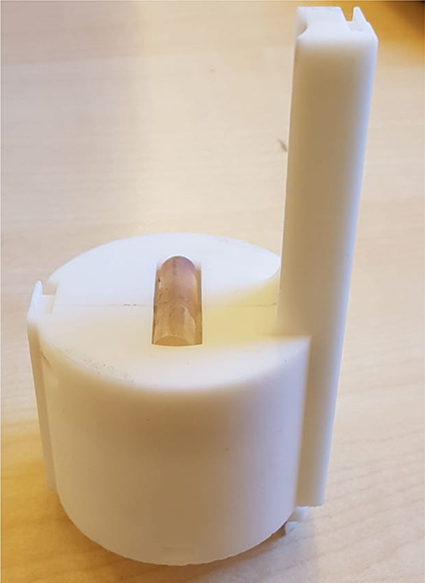 |
Figure 7 NITINOL switch with a closed shell. |
A switching time of exactly 3 s was not reached with the theoretically calculated settings of the power supply. One reason for this may be the deviation of the theoretically calculated resistance of the NITINOL wire and the actual one. However, a much more important reason might be the fact that, in theory, external influences such as the cooling of the wire by ambient temperature were not taken into account.
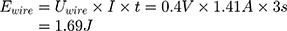
As expected, more energy is needed than theoretically calculated. If the values of Table 2 are averaged and plotted on a graph (Figure 8), an energy of around 1.8 J can be read for a switching time of 3 s. The theoretically required energy (1.69 J) for a switching time of 3 s is less than the measured (1.8 J). The reason for this could be external influences, like the energy lost to the environment, which are not considered in the theoretical calculation.
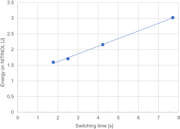 |
Figure 8 Average energy on NITINOL dependent on the switching time. |
Depending on the ambient temperature, the switching time and the associated energy consumption may change. Below 20°C, more energy and a longer switching time would be required than when the ambient temperature is above 20°C.
With the averaged force measurement for the NITINOL wire (0.392 mm diameter) of 14.56 N, the target force of 15 N is almost reached. Possible reasons for the deviation could be friction in the measurement setup or measurement inaccuracies.
Three parallel single-cell lithium-ion batteries are able to supply the needed power for the NITINOL actuator. Other than expected, less energy than calculated is needed. One reason could be measurement inaccuracies in taking the time. To keep the wire contracted, it is not necessary to constantly power with the same energy than for the heat-up process. The only energy to add, to keep the wire contracted, is the energy lost to the environment. Lowering the energy while the wire needs to hold its deformation would increase the cycle number of one battery enormously.
While checking the components for their MRI compatibility, no significant magnetic attraction was found. The image quality was not affected in both states of the actuator (deactivated/activated).
MRI image artifacts are also present using NITINOL31 due to the magnetic susceptibility of the material. For stents – used in the literature example – made of NITINOL, the biggest influence on the size and shape of the artifacts is due to the geometry of the device that can create local magnetic field variations.32 Consequently, as our NITINOL wire does not involve any pattern distribution but rather a straight line, it can be assumed that the artifacts are reduced significantly. Since the wire is shorter than half the wavelength of the radio frequencies used, and as it is not in direct contact with the patient skin we can also assume that there will not be any detrimental effects to patient safety.
When using the NITINOL wire as a switch, keep in mind that it can reach temperatures above 100°C. The wire must, therefore, be insulated so that no damage to the patient or adjacent components occurs.
The area of the switch to which the wire is attached should be made of temperature-resistant material. For a secure attachment of the wire, the two-component adhesive (Original Cold Weld Formula Steel Reinforced Epoxy, J-B WELD, USA) has worked well. The adhesive hardens after 24 hrs and can withstand temperatures above 300°C.
The power supply cables need to be soldered to the NITINOL wire ends. Due to the titanium oxide layers, this is not feasible or at least difficult to realize without machining the wire ends. There are two option s for treatment. The titanium oxide layer can either be removed with smeared paper or chemically, eg, by a flux.
This switch could open, for example, pressure valves and control the resulting flow rate. One possible example could be an MRI-compatible contrast injector as used for the base calculations. Another application could be to use the switch as a linear motor in which two different states can be switched.
Conclusion
The NITINOL actuator is an ideal alternative to common actuators. Its reliability, compactness and simple construction are good reasons for use in future applications to be used in a strong magnetic field, like in or close to MRI systems. The NITINOL actuator is inexpensive (around 5 €) and all of its used components are fully MRI compatible. Although the batteries are slightly magnetic, they pose no danger to the patient if firmly attached and integrated due to their low weight. By changing the wire diameter or using a lever arm, the force and travel can be adapted to the individual needs.
Acknowledgments
We would like to thank FC Stimulate (Otto-von-Guericke University, Germany) especially Cindy Lübeck and Enrico Pannicke for their help with the experiments. This study was financially supported by the Federal Ministry of Education and Research (BMBF) in the context of the “INKA” project (Grant Number 03IPT7100X) and BMWI easyJector project (Grant Number ZF4206101AK6).
Disclosure
The authors report no conflicts of interest in this work.
References
1. Tsekos NV, Khanicheh A, Christoforou E, Mavroidis C. Magnetic resonance–compatible robotic and mechatronics systems for image-guided interventions and rehabilitation: a review study. Annu Rev Biomed Eng. 2007;9(1):351–387. doi:10.1146/annurev.bioeng.9.121806.160642
2. Keeler EK, Casey FX, Engels H, et al. Accessory equipment considerations with respect to MRI compatibility. J Magn Reson Imaging. 1998;8(1):12–18. doi:10.1002/jmri.1880080107
3. Friebe M, Sachtler D, Hellwig S, Schlüter M, Sakas G, Jorczyck U (2008) Autonomous navigation assistant for MRI guided interventions.
4. Friebe M, Sanchez J, Balakrishnan S, et al. In-room ultrasound fusion combined with fully compatible 3D-printed holding arm - rethinking interventional MRI. Med Devices. 2018;11:77–85. doi:10.2147/MDER.S150459
5. Vartholomeos P, Bergeles C, Qin L, Dupont PE. An MRI-powered and controlled actuator technology for tetherless robotic interventions. Int J Rob Res. 2013;32(13):1536–1552. doi:10.1177/0278364913500362
6. Shellock FG. Radiofrequency energy-induced heating during MR procedures: a review. J Magn Reson Imaging. 2000;12(1):30–36. doi:10.1002/1522-2586(200007)12:1<30::AID-JMRI4>3.0.CO;2-S
7. Dempsey MF, Condon B, Hadley DM. Investigation of the factors responsible for burns during MRI. J Magn Reson Imaging. 2001;13(4):627–631. doi:10.1002/jmri.1088
8. Chinzei K, Kikinis R, Jolesz F. MR compatibility of mechatronic devices. Des Criteria Lect Notes Comput Sci. 2006;1679:1020–1030. doi:10.1007/10704282_111
9. Ninneman S (2016) Momentary air switches, alternate latching air switch Available from: http://presair.com/momentary-alternate-latching-air-switches/.
10. Higuchi T. Next generation actuators leading breakthroughs. J Mech Sci Technol. 2010;24(1):13–18. doi:10.1007/s12206-009-1153-2
11. Mansour SZ, Seethaler RJ. Simultaneous displacement and force estimation of piezoelectric stack actuators using charge and voltage measurements. IEEE/ASME T Mech. 2017;22(6):2619–2624. doi:10.1109/TMECH.2017.2757931
12. Zhu W, Chen G, Rui X. Modeling of piezoelectric stack actuators considering bonding layers. J Intell Mater Syst Struct. 2015;26(17):2418–2427. doi:10.1177/1045389X15575083
13. Kumada A. A piezoelectric ultrasonic motor. Jpn J Appl Phys. 1985;24(S2):739. doi:10.7567/JJAPS.24S2.739
14. Shokrollahi P, Drake JM, Goldenberg AA. Ultrasonic motor-induced geometric distortions in magnetic resonance images. Med Biol Eng Comput. 2018;56(1):61–70. doi:10.1007/s11517-017-1665-3
15. Shokrollahi P, Drake JM, Goldenberg AA. Signal-to-noise ratio evaluation of magnetic resonance images in the presence of an ultrasonic motor. Biomed Eng Online. 2017;16(1):45. doi:10.1186/s12938-017-0331-1
16. Riener R, Villgrattner T, Kleiser R, Nef T, Kollias S. fMRI-Compatible Electromagnetic Haptic Interface.
17. Stoianovici D, Song D, Petrisor D, et al. “MRI Stealth” robot for prostate interventions. Minim Invasive Ther Allied Technol. 2007;16(4):241–248. doi:10.1080/13645700701520735
18. Kim D, Kobayashi E, Dohi T, Sakuma I. A new, compact MR-compatible surgical manipulator for minimally invasive liver surgery. In: Dohi T, Kikinis R, editors. Medical Image Computing and Computer-Assisted Intervention — MICCAI 2002. Berlin, Heidelberg: Springer Berlin Heidelberg; 2002:99–106. doi:10.1007/3-540-45786-0_13
19. Stoianovici D, Patriciu A, Petrisor D, Mazilu D, Kavoussi L. A new type of motor: pneumatic step motor. IEEE ASME Trans Mechatron. 2007;12(1):98–106. doi:10.1109/TMECH.2006.886258
20. Cheng SS, Kim Y, Desai JP. Modeling and characterization of shape memory alloy springs with water cooling strategy in a neurosurgical robot. J Intell Mater Syst Struct. 2017;28(16):2167–2183. doi:10.1177/1045389X16685443
21. Vartholomeos P, Qin L, Dupont PE. MRI-powered actuators for robotic interventions.
22. Uchino K. Piezoelectric ultrasonic motors. Overview Smart Mate Struct. 1998;7:273. doi:10.1088/0964-1726/7/3/002
23. Chen Y, Kwok K-W, Tse ZTH. A MR-conditional high-torque pneumatic stepper motor for MRI-guided and robot-assisted intervention. Ann Biomed Eng. 2014;42(9):1823–1833. doi:10.1007/s10439-014-1049-x
24. Guo Z, Dong Z, Lee K, et al. Compact design of a hydraulic driving robot for Intraoperative MRI-guided bilateral stereotactic neurosurgery. EEE Robot Autom Lett. 2018;3(3):2515–2522. doi:10.1109/LRA.2018.2814637
25. Chu W-H, Mehregany M, Mullen RL. Analysis of tip deflection and force of a bimetallic cantilever microactuator. J Micromech Microeng. 1993;3:4–7. doi:10.1088/0960-1317/3/1/002
26. Kennedy SP. Material Characterization of Nitinol Wires for the Design of Actuation Systems [master thesis]. San Luis Obispo: California Polytechnic State University; 2013.
27. Mohd Jani J, Leary M, Subic A, Gibson MA. A review of shape memory alloy research, applications and opportunities. Mater Des. 2014;56:1078–1113. doi:10.1016/j.matdes.2013.11.084
28. Jähne R (2017) Datasheet Nitinolwire, Available from: https://www.nitinol-shop.com/.
29. Baker I. Fifty Materials that Makes the World. Cham: Springer International Publishing; 2018. 137–142. doi:10.1007/978-3-319-78766-4_26
30. Stanford MK. Thermophysical Properties of 60-NITINOL for Mechanical Component Applications 12. NASA/TM-2012-216056. Cleveland, OH: Glenn Research Center; 2012.
31. Bartels LW, Smits HFM, Bakker CJG, Viergever MA. MR imaging of vascular stents: effects of susceptibility, flow, and radiofrequency eddy currents. J Vasc Interv Radiol. 2001;12(3):365–371. doi:10.1016/S1051-0443(07)61918-6
32. Melzer A, Michitsch S, Konak S, Schaefers G, Bertsch T. Nitinol in magnetic resonance imaging. Minim Invasive Ther Allied Technol. 2004;13:261–271. doi:10.1080/13645700410020269
 © 2019 The Author(s). This work is published and licensed by Dove Medical Press Limited. The
full terms of this license are available at https://www.dovepress.com/terms
and incorporate the Creative Commons Attribution
- Non Commercial (unported, 3.0) License.
By accessing the work you hereby accept the Terms. Non-commercial uses of the work are permitted
without any further permission from Dove Medical Press Limited, provided the work is properly
attributed. For permission for commercial use of this work, please see paragraphs 4.2 and 5 of our Terms.
© 2019 The Author(s). This work is published and licensed by Dove Medical Press Limited. The
full terms of this license are available at https://www.dovepress.com/terms
and incorporate the Creative Commons Attribution
- Non Commercial (unported, 3.0) License.
By accessing the work you hereby accept the Terms. Non-commercial uses of the work are permitted
without any further permission from Dove Medical Press Limited, provided the work is properly
attributed. For permission for commercial use of this work, please see paragraphs 4.2 and 5 of our Terms.