Back to Journals » International Journal of Nanomedicine » Volume 11
Effects of intermolecular interactions on the stability of carbon nanotube–gold nanoparticle conjugates in solution
Authors Konczak L, Narkiewicz-Michalek J, Pastorin G, Panczyk T
Received 21 July 2016
Accepted for publication 13 September 2016
Published 7 November 2016 Volume 2016:11 Pages 5837—5849
DOI https://doi.org/10.2147/IJN.S117858
Checked for plagiarism Yes
Review by Single anonymous peer review
Peer reviewer comments 4
Editor who approved publication: Dr Thomas Webster
Lukasz Konczak,1 Jolanta Narkiewicz-Michalek,2 Giorgia Pastorin,3 Tomasz Panczyk1
1Institute of Catalysis and Surface Chemistry, Polish Academy of Sciences, Cracow, 2Department of Chemistry, Maria Curie-Sklodowska University, Lublin, Poland; 3Department of Pharmacy, National University of Singapore, Singapore
Abstract: This work deals with the role of intermolecular interactions in the stability of a carbon nanotube (CNT) capped by functionalized gold nanoparticles (AuNPs). The importance of such a system is due to its potential application as a pH-controlled drug carrier. Our preliminary experimental studies showed that fabrication of such a nanobottle/nanocontainer is feasible and it is possible to encapsulate the anticancer drug cisplatin inside the inner space of a CNT and seal its ends by functionalized AuNPs. The expected behavior, that is, detachment of AuNPs at acidic pH and the release of cisplatin, was, however, not observed. On the other hand, our theoretical studies of chemically identical system led to the conclusion that the release of cisplatin at acidic pH should be observed. Therefore, in this work, a deeper theoretical analysis of various factors that could be responsible for the disagreement between experimental and theoretical results were performed. The study found that the major factor is a large dispersion interaction component acting between CNT and AuNP in solution in the case of the experimental system. This factor can be controlled to some extent by tuning the system size or the ratio between AuNP diameter and CNT diameter. Thus, such kind of a pH-sensitive drug carrier is still of great interest, but its structural parameters need to be properly adjusted.
Keywords: hydrazone bond, drug delivery, dispersion interactions, cisplatin, acidic pH
Introduction
Unique molecular structure of carbon nanotubes (CNTs), that is, tubular shape with the inner hollow space, attracts research interests in many areas of science and technology. Hydrogen storage,1 gas separation2 or sensor applications,3 nanoreactors,4 or catalysts5 are a few examples of their diverse application areas. CNTs are also extensively studied in medical sciences mainly as materials for tissue engineering6,7 and drugs carriers.8,9
Numerous studies of CNT as drugs carriers are almost exclusively devoted to incorporation of drugs, targeting factors or compounds improving their biocompatibility to the external walls of CNT.8,10,11 Such hybrid materials often reveal highly interesting properties like ability to release the drug in response to various chemical or physical factors. It is well known that tumor microenvironment reveals several specific properties that can be utilized for controlled drug release. High reductive environment of tumor cells or reduced pH due to lactic acid production caused by anaerobic glycolysis were studied as triggering factors for the release of cisplatin (CDDP) from CNTs.12 CNTs were also studied as carriers of many other classes of drug molecules including topoisomerase inhibitors,13 anthracyclines,14 or folic acid antagonists.15 Possible toxicity of CNTs can be removed by a proper chemical treatment leading to purification (removal of the residual heavy metals in CNT) and oxidation to produce hydrophilic carboxyl functional groups on the tips and defect sites and/or additional functionalization by polyethylene glycol, polyvinyl alcohol, or other highly hydrophilic moieties.13–15 This strategy leads to production of biocompatible and nontoxic CNTs.
Encapsulation of a drug in the inner hollow cavity of a CNT offers perfect isolation of the drug from the environment. Thus, this strategy should lead to a significant reduction of side effects often associated with the administration of drugs provided that drugs release can be initiated exclusively at the target site. Indeed, there are several reports concerning either theoretical or experimental realizations of such a mechanism.12,16–19 In a recent experimental work,12 we proposed a model of carbon nanobottle capped by gold nanoparticles (AuNPs) that are covalently appended at the tips of CNT by cleavable linkers, which are sensitive to external triggers such as low pH. We successfully tethered AuNPs (sized similarly as CNT’s inner diameter, ie, 40 nm) at the proximities of CNT. These AuNPs serve as seal for the open ends of CNT and prevent leakage of encapsulated CDDP, a widely used anticancer drug. However, the applied hydrazone bonds containing linkers were ostensibly insusceptible to acidic conditions, thus precluding the desired controlled release of CDDP. In another work,18 we theoretically studied a chemically identical system but obviously the studied model was significantly smaller in size (~40 times), which was free of defects that are common in the case of actual systems and it was studied in conditions where no interactions with other large particles existed. This theoretical analysis led to the conclusion that in the case of CDDP-filled single-walled nanotube, the free energy barrier associated with the detachment of AuNP is relatively low (~25 kJ mol−1), meaning that spontaneous detachment of the AuNP seal and the release of CDDP should occur at acidic pH.
The aforementioned contradictory results need careful analysis as the studied systems reveal potentially useful properties. Therefore, the aim of this work is a closer analysis of various factors that can be responsible for the inconsistency in experimental and theoretical studies. As both theoretical and experimental models are chemically identical and the differences concern only their sizes, presence of defects in actual system, and contribution from many-body interactions, we are going to address these factors in this work.
Methods
Definition of analyzed systems
The pH change from neutral to acidic occurring in tumor tissues because of hypoxia is a natural and promising factor that can be utilized for triggering drug release. This range of pH change is not very wide (from 7.4 to ~5.5), but it is enough to initiate structural transformations of some organic molecules.
Hydrazone bonds hydrolyze into corresponding aldehyde and hydrazide at slightly acidic pH.20,21 We utilized this property for construction of our model system, which is intended to work as a pH-controlled nanocontainer.18 The system is composed of a single-walled CNT, linkers containing hydrazone segments, and AuNPs. The CNT tips are functionalized by hydrazide groups (Figure 1). This kind of functionalization can be reached by treating pristine nanotubes with oxidizing agents such as HNO3, KMnO4/H2SO4, O2, K2Cr2O7/H2SO4, or OsO4. This oxidizing procedure is usually known as “defect functionalization” because it takes place at the ends or in correspondence of preexisting defects of CNT; if done under mild conditions, it preserves the macroscopic features of CNT without losing their electronic and mechanical properties.22 In the next step, the carboxyl groups generated during the oxidation stage react with hydrazine leading to hydrazide fragments localized at the CNT tips.12
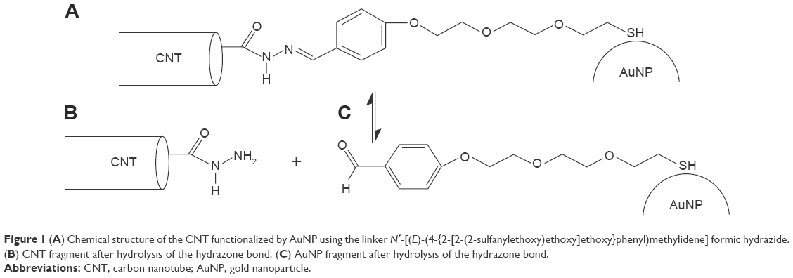 | Figure 1 (A) Chemical structure of the CNT functionalized by AuNP using the linker N′-[(E)-(4-{2-[2-(2-sulfanylethoxy)ethoxy]ethoxy}phenyl)methylidene] formic hydrazide. (B) CNT fragment after hydrolysis of the hydrazone bond. (C) AuNP fragment after hydrolysis of the hydrazone bond. |
The chemical links between CNT and AuNP are not the only factors keeping these two species together in aqueous solution. We previously determined the free energy barriers associated with the detachment of AuNPs from CNT tips. Those barriers were huge in case of solvent-filled nanotubes meaning that spontaneous detachment is kinetically blocked.18 However, in case of CDDP-filled nanotubes, the barriers dropped down significantly and we concluded that the detachment and subsequent release of CDDP should be feasible in actual systems. Other experimental studies of chemically identical system led to the conclusion that CDDP is tightly encapsulated in the nanotube interior at neutral pH. But at acidic pH, almost no release of CDDP was observed.12
Molecular topology and force field for the studied systems
The topology of the studied CNT was built using self-designed scripts. We generated a single-walled zigzag CNT with chirality (20, 0). Its diameter and length were 15.66 and 40 Å, respectively. Internal degrees of freedom of the CNT were described by the many-body adaptive intermolecular reactive empirical bond order (AIREBO) potential. CNT was treated as a flexible body, which could even undergo structural rearrangements in case of strong interactions with the environment. Interaction of the CNT with other components of the system was described using the standard Lennard–Jones (LJ) potential for carbon atoms. The LJ parameters for carbon atoms were set up according to AMBER force field. No partial charges were set up for carbons creating the CNT; the only exception was six terminal atoms to which the linkers were attached.
The AuNPs were created as spherical slabs of the fcc crystal with the lattice constant 4.073 Å. Their diameter was 10 Å; thus, every AuNP contains 43 gold atoms. The internal structure of AuNP was kept rigid during the calculations. Interaction of AuNPs with other components of the system was described using the standard LJ potential. For determination of the LJ parameters for gold atoms, we utilized the procedure of recovering their values from known value of the material’s Hamaker constant. This constant has a precise definition and is directly related to the LJ parameters.
For example, by assuming A =50·10−20 J for gold, density ρAu =19.3 g cm−3, and σ =3.215 Å for the case of gold-carbon interaction, we get εAu/C =1.983 kJ mol−1. The individual σAu can be identified with the atomic diameter, ie, 2.88 Å.
|
|

In the case of linkers, we currently consider only the cleaved state corresponding to the acidic pH. Thus, we deal with two parts of the linker separately. One part is covalently bonded to the CNT tip; more precisely, the hydrazide fragments were tethered to three terminal carbons distributed uniformly on each CNT tip. Standard harmonic bonds between C-C (one belonging to the CNT and the second belonging to the hydrazide fragment) were created. The second part of the linker was tethered to the AuNP by creating a rigid bond between gold and sulfur atoms (standard thiol bond is formed). Twenty-five linkers were attached to every AuNP, and the AuNP-sulfur bonds were uniformly distributed on the AuNP surface. All interaction parameters and topology associated with the linkers were generated using automatic atom and bond type perception scheme implemented in AmberTools 12. Atomic partial charges were determined using R.E.D. tools.18
The force field, ie, the LJ parameters and partial charges for CDDP, was directly taken from the work by Lopes et al.23 We used the non-aquated form of CDDP mainly for simplicity. The other reasons were localization of CDDP molecules inside the CNT and the relatively small number of water molecules able to penetrate the interior of CNT in the presence of CDDP.
The detailed description of all force field parameters and their values were provided in the supporting information file linked to our recent publication.18 This work uses the same computational model as in the study by Panczyk et al;18 therefore, the force field parameters are identical.
Calculation details
All calculations were performed using the large-scale atomic/molecular massively parallel simulator (LAMMPS) code in NPT ensemble using 1.5 fs time step.24 The pressure and temperature were controlled using the Nose-Hoover barostat.
The TIP3P water model was used, and the SHAKE algorithm was applied to make water molecules rigid. Water molecules were allowed to enter the nanotube interior at the initial stage of a given system construction by an unbiased molecular diffusion mechanism. For that purpose, AuNPs were kept at some distance from the nanotube tips by an extra spring force. The CDDP molecules placed initially in the CNT interior were locked by reflecting walls placed at the CNT tips until the CNT interior became uniformly filled by water molecules. The number of water molecules penetrating the inner cavity of the nanotube, obtained using the earlier procedure, was 45.
The ionic strength of solution 0.145 mol L−1 was reached by incorporation of suitable numbers of Na+ and Cl− ions. The cutoff for intermolecular interactions was 12 Å. Before any production run, heating to 400 K for 0.3 ns and then cooling to 310 K for 0.3 ns were performed. After an equilibration period taking ~0.5 ns, the production runs were done taking at least 3 ns for each system.
Results and discussion
Intermolecular interactions
At neutral pH, the hydrazone bonds keep AuNPs adjacent to the CNT tips, so that the CDDP molecules cannot escape from the nanotube interior. This conclusion comes from either molecular dynamics (MD) simulations18 or experimental observations.12 Thus, further analysis of this system state is not needed. The critical step is detachment of AuNPs at acidic pH when the hydrazone bonds linking the AuNP with CNT undergo spontaneous cleavage, leading further to two chemically distinct components (Figure 1B and C). However, as we found in a previous study, the dispersion forces still act and the detachment of the AuNP from the CNT is accompanied by free energy barriers.18 Namely, they are over 250 kJ mol−1 in the case of solvent-filled CNT, and about 20-30 kJ mol−1 in the case of CNT filled in CDDP.18 Obviously, in actual application, the system must be filled in CDDP or other drug molecules. Therefore, we focus on this particular situation.
The problem that we are going to address is the influence of other species on the behavior of the nanocontainer. In actual application, any drug delivery system must be considered in the context of crowded conditions. Presence of proteins or other heavy (polyatomic) species might affect its properties significantly. However, direct analysis of such factors is difficult due to the presence of a large number of possible biocompounds, which the nanocontainer can meet at the target site. Thus, we will limit the analysis to a very likely and well-defined case, that is, the nanocontainer meets another nanocontainer (or its part) at the target site.
Such an event was modeled in the following manner: we placed two identical nanocontainers in parallel orientation, with an axial distance between them equal to 32 Å. The system was subjected to heating to 400 K for 0.3 ns, cooling to 310 K for another 0.3 ns, and 3 ns equilibration run. During the aforementioned treatment, both the nanocontainers were kept at their initial positions by applying spring forces, so that the distance between them and orientation were conserved. In the next step, the spring forces were removed and the nanocontainers were allowed to move freely. This stage of simulation lasted for 3 ns and it was enough to observe either the collision between the nanocontainers or leakage of CDDP from the nanotubes interiors.
Figure 2A and B shows the simulation snapshots for illustration of the pre-collision state and post-collision state, respectively. Because we can define many interaction pairs between any components of the system, it would lead to difficulty in analysis. Thus, it is more transparent to analyze only those interaction pairs that change significantly when the system performs structural transformation. Looking at Figure 2 we can notice that both AuNPs, initially attached to the bottom CNT, have been detached upon collision. Table 1 shows some values of the energetic parameters associated with those AuNPs that are quite interesting to analyze.
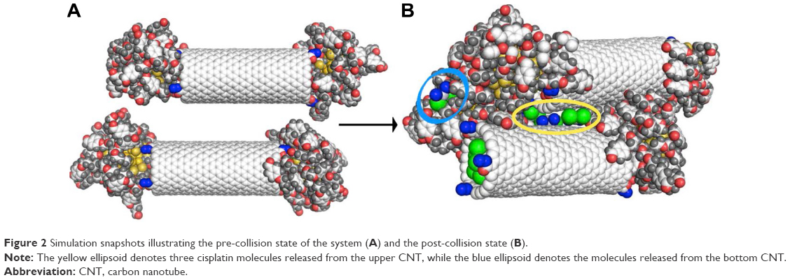 | Figure 2 Simulation snapshots illustrating the pre-collision state of the system (A) and the post-collision state (B). |
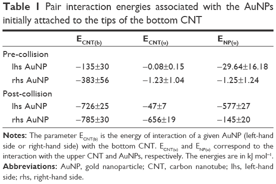 | Table 1 Pair interaction energies associated with the AuNPs initially attached to the tips of the bottom CNT |
Analysis of the parameters shown in Table 1 leads to several conclusions. We can notice a significant difference in interaction energies of the left-hand side (lhs) and right-hand side (rhs) AuNPs with the bottom CNT at the pre-collision state. The simulation snapshot suggests that ECNT(b) of both sides should be similar because visually both AuNPs are attached to the CNT tips in a very similar way. However, as we found in our previous study,18 the energies ECNT(b) depend strongly on the degree of incorporation of linkers to the internal space of CNT. The presence of CDDP reduces such a phenomenon significantly but CDDP is not distributed within the CNT absolutely uniformly. Therefore, we observe a difference in energies (−135 vs −383 kJ mol−1). The differences in interaction energies with the upper CNT and upper AuNPs are obviously due the applied arrangement of two nanocontainers at the pre-collision state.
The post-collision state corresponds to total detachment of the lhs AuNP from the tip of the bottom CNT and transfers to its sidewall. This uncapping process is the result of collision and coalescence of both nanocontainers into a single cluster. Again, the most interesting changes can be observed in interaction energy of the lhs AuNP. That energy drops to −726 kJ mol−1 and it means that binding of the AuNP on the sidewall is stronger than on the tip. The rhs AuNP was partially detached from the tip as well but its linkers localized either on the internal or external walls of the CNT. As a result, its interaction energy with the CNT became higher than it was before collision.
Interestingly, the upper CNT released four CDDP molecules during the collision process. The final state seems to be still the capped one, but its tightness is significantly reduced due to strong interaction between AuNPs (see ENP(u) in Table 1). As can be seen in Figure 2, both lhs AuNPs fused into one cluster localized on the sidewall of the bottom CNT. We can thus conclude that interactions between multiple nanocontainers facilitate the release of CPT provided that the covalent bonds have already been broken. Calculations of the free energy barriers are not necessary in this case since we observed spontaneous release of CDDP within the applied simulation time without any bias potential.
Another event that is likely to occur in crowded conditions is interaction of the nanocontainer with a third AuNP, which can either come from the bulk or represent a possible residual sidewall functionalization. Obviously, in the latter case, the AuNP is chemically disconnected from the CNT in acidic conditions when the hydrazone linkers underwent hydrolysis. Figure 3 shows the simulation snapshot concerning such a case.
 | Figure 3 Simulation snapshots of the system with an extra AuNP located on the CNT sidewall. |
The third AuNP was initially placed in the middle of the CNT (Figure 3A), and standard heating, cooling, and equilibration stages followed by 3 ns production run were performed. Analysis of the trajectory of that extra AuNP leads to the conclusion that it readily moves on the surface of CNT. However, its contacts with AuNPs capping the CNT tips (Figure 3B) did not lead to destabilization of their positions. Obviously, no release of CDDP was triggered by the presence of the third AuNP on the CNT sidewall.
Analyses of pair interaction energies between AuNPs and CNT confirm the conclusions drawn from simple visual analysis of the MD trajectories. Table 2 shows values of various pair energies. In this case, we can still notice significant differences in pair energies for the interaction of AuNPs with the CNT tips though both nanoparticles are in formally equivalent positions. This is due to various degrees of incorporation of linkers to the nanotube interior. Interaction energy of the extra AuNP with CNT sidewall (Ee-CNT) is much bigger than the energy of interaction with the tips. However, due to energy barriers, a spontaneous transfer of the nanoparticles from the tips to the sidewall does not occur. Finally, we can see that the interaction energy of the extra AuNP with the other nanoparticles is very small. This is due to relatively short time spent by the extra nanoparticle in the vicinity of AuNPs attached to the tips. We can also notice that the close contact of the extra AuNP with the rhs AuNP capping the CNT leads to its slight destabilization. The interaction energy Er-CNT dropped by more than 100 kJ mol−1 when compared to position A, but it is not enough to trigger the detachment of the rhs AuNP from the CNT tip.
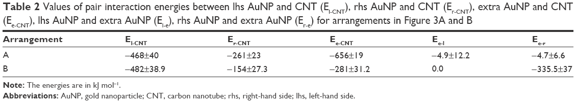 | Table 2 Values of pair interaction energies between lhs AuNP and CNT (El-CNT), rhs AuNP and CNT (Er-CNT), extra AuNP and CNT (Ee-CNT), lhs AuNP and extra AuNP (El-e), rhs AuNP and extra AuNP (Er-e) for arrangements in Figure 3A and B |
Another interesting case is the interaction of the nanocontainer with the bare surface of another CNT in solution. This is actually the most likely case to occur in crowded conditions. CNTs are usually much longer than the model CNT utilized in our computations and therefore the most representative interaction zone of CNTs is their external surface. We studied two arrangements of the base nanocontainer and the extra CNT acting as “invader”.
The first arrangement is illustrated in Figure 4A. At the beginning of the simulations, the extra CNT was put in the middle of the CNT belonging to the nanocontainer and oriented in such a way that it formed 90° angle with the axis of the nanocontainer. The system was subjected to heating, cooling, and equilibration stages. During this initial treatment, both the CNT and the metallic cores of the AuNPs were enforced to keep their initial positions unchanged. The linkers covering both the AuNPs were allowed to move freely according to MD integration procedure. After the equilibration, the initial constraints were removed and the calculations were continued for another 3 ns. The final state of the system is illustrated in Figure 4B and C.
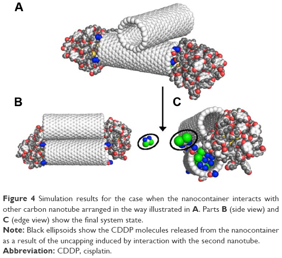 | Figure 4 Simulation results for the case when the nanocontainer interacts with other carbon nanotube arranged in the way illustrated in A. Parts B (side view) and C (edge view) show the final system state. |
As we can see, the second nanotube turned around and ended up in parallel orientation to the nanocontainer. At the same time, it destabilized the capped state of the nanocontainer and the release of CDDP occurred. Looking at pair interaction energies, collected in Table 3, we can conclude that there appears a competition for a takeover of AuNPs between both the CNTs. Pair interaction energy Er-eCNT became higher than Er-CNT and we can see that rhs AuNP partially detached from the CNT tip and moved toward the extra CNT. The state of the lhs AuNP is less affected by the presence of the extra CNT, but we can still notice some shift of the linker layer toward the extra CNT.
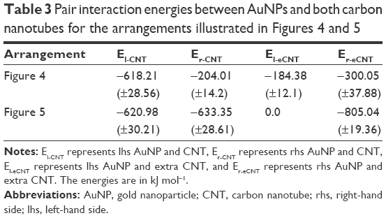 | Table 3 Pair interaction energies between AuNPs and both carbon nanotubes for the arrangements illustrated in Figures 4 and 5 |
The second studied arrangement of the nanocontainer and the extra CNT is illustrated in Figure 5A. In this case, the extra AuNP is located in a close distance to the rhs AuNP, and the angle between CNTs is 90°. Analogous calculations for this initial arrangement led to the final state, as illustrated in Figure 5B and C. Similarly like before, we can notice changes in the spatial structure the nanocontainer induced by the interaction with the second CNT. The pair interaction energies (collected in Table 3) prove strong interaction of the rhs AuNP with the extra CNT leading to total uncapping of the nanocontainer. This is followed by the release of CDDP molecule from the nanocontainer.
 | Figure 5 Simulation results for the case when the nanocontainer interacts with other carbon nanotube arranged in the way illustrated in part A. Parts B (side view) and C (edge view) show the final system state. |
It seems that the interaction of AuNPs with the sidewall of the second CNT facilitates the release of drug molecules most effectively when comparing all the aforementioned studied cases. At the same time, the last arrangement is also the most likely to occur in crowded conditions (at least in case of multiple nanocontainers in solution). We can therefore conclude that the analyzed nanocontainer should easily release drug molecules at acidic conditions when the hydrazone bonds hydrolyzed. But the earlier conclusion is still limited to this particular system size. Larger systems are likely to be more resistant to uncapping due to much bigger dispersion interaction component.
Length scale dependence of intermolecular interaction energy
Direct analysis of the length scale dependence of the uncapping process at acidic conditions is not possible due to computational limitations. Larger simulation boxes would lead to much longer and actually unreasonable computation times. Therefore, we need to utilize analytical approaches (formulas), which will help to estimate how the dispersion interactions grow when we approach larger and larger system sizes. In the case of AuNP cores, there are exact analytical methods for computation of dispersion interaction energies due to their spherical symmetry and uniform structure. The linker layers are more difficult because their spatial structure will mainly depend on the size of gold core. This is because every single atom belonging to linker molecules is attracted by the gold core. So, if the attraction is weak, then the linkers create a loose structure, but in the case of strong attraction, the linker layer can be hard and densely packed.
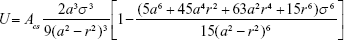
Dispersion interaction energy U of a large object with a single atom can be, according to the Hamaker theory,25 computed as integral of pairwise LJ interactions taken over the volume of the object with atomic density ρ(r),
|
|
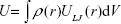
where V is the volume of the object and ULJ(r) is the LJ pairwise potential at a distance r between the probe atom and some point within the object volume. For a spherical nanoparticle, equation (eq) (2) can be integrated analytically giving the following convenient formula:26
|
|
By using the definition of the Hamaker constant 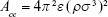 ,27 we can express Acs in eq (3) as
 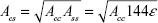 . In eq (3), a is the radius of the nanoparticle, whereas ε and σ are the usual LJ parameters, and r is the center-center distance between the atom and the nanoparticle. The factor 144ε is a formal Hamaker constant for the single atom interactions Ass, and it is a result of assuming that the number density of single atom is 1 per volume occupied by a sphere of radius σ/2, that is,
  .
.
Thus, eq (3) offers a simple and fairly exact method for computation of the dispersion interaction energy between AuNP and an atom belonging to the linker layer. Of course, the linker layer is composed of molecules and their structure will also depend on the interatomic interactions between atoms belonging to other linker molecules or atoms within the same linker. However, the interaction energy between AuNP and the atom is the most important when we need to track possible changes in linker layer structure with the increasing size of the nanoparticle.
The potential energy function (3) has similar shape like the standard LJ potential. So, it reveals a single minimum at close distance from the nanoparticle surface. The depth of this minimum Um controls the behavior of an atom in the neighborhood of the nanoparticle. A deep minimum leads to strong attraction of the atom and its immobilization in the potential energy well (adsorption). But in case of a shallow minimum, the attraction may be too weak to keep the atom in the neighborhood of the nanoparticle due to thermal agitation. Therefore, the crucial parameter is the thermal average of the interaction energy predicted by eq (3).
The canonical partition function Z for the system composed of a single atom interacting with the nanoparticle according to potential (3) is given by the following formula:
|
|
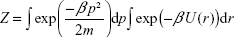
where p is the momentum vector, m is the mass of the atom (the nanoparticle is considered as static), and β = (kBT)−1. The thermal average of the total energy is thus given by:
|
|
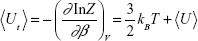
where
|
|
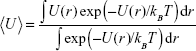
The first term on the rhs of eq (5) is the kinetic energy of the atom, while the second one describes its mean potential energy, <U>. The atom will be trapped in the potential energy well generated by the nanoparticle when <Ut> is less than zero, otherwise the atom will not be localized at the nanoparticle.
It is, therefore, interesting to analyze how the mean interaction energy of a probe carbon atom <U> changes with the increasing AuNP size. Figure 6 shows how the depth of the potential energy well Umin and the thermal average of potential energy <U> change with the nanoparticle size. Figure 6 also shows the example of a typical shape of the potential (3) for a =100 Å.
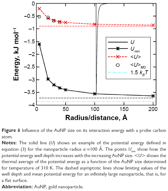 | Figure 6 Influence of the AuNP size on its interaction energy with a probe carbon atom. |
As can be seen in Figure 6, the Hamaker potential (3) reveals a single minimum Umin at some distance from the nanoparticle surface. Similarly like the standard LJ potential, it has rapidly increasing repulsive branch at very short distances and long tail at large distances. The most important property of the potential (3) is Umin dependence on the nanoparticle radius. The potential energy well depth quickly increases with the increasing AuNP size for small nanoparticle sizes. But it becomes almost size independent for AuNP radius greater than 100 Å. This effect is due to smaller and smaller local surface curvature as the radius increases. Thus, for AuNP radii greater than 100–200 Å, the potential energy well depth will be actually very close to its value for a flat surface (denoted as dashed asymptotic line).
The structure of the linker layer will, however, be determined by the thermal average of the potential energy. In Figure 6, we plotted such thermal average for the probe carbon atom determined from eq (6). Because we assume that the probe carbon atom belongs to the linker molecule, the averaging was done in the range from r = a to r = rm, where rm =18 Å is the linker molecule length. As we can see, <U> behaves similarly like Umin, but its absolute values are much smaller. We can still observe the most significant increase of <U> for small nanoparticles, while for the large ones the average energy is almost size independent and close to the limiting value for a flat surface. However, the absolute values of the average binding energies are always much smaller than 1.5 kBT =3.86 kJ mol−1 in the considered temperature. Therefore, the dispersion interaction component of the binding energy of the linker is weak and the linkers will form a soft layer on the AuNP surface no matter what is the nanoparticle size. This is quite a surprising conclusion because the Hamaker constant for metals is very high and we expected much stronger interaction for big nanoparticles. Thus, at some AuNP size, the linker molecules were supposed to make a collapse into a dense and hard layer on the AuNP surface.
The model encoded in eqs (4)–(6) is obviously very crude; therefore, we verified its predictions by direct MD simulations for AuNPs radii up to 40 Å. As can be seen in Figure 6, the mean interaction energy of linker atoms with the gold core agrees well with the theoretical prediction given by eq (6). The discrepancy for a =5 Å is a common effect of application of the Hamaker potential (3) to small objects. The summation of pairwise contributions from every single pair of atoms cannot be well represented by the integration (continuum approach) encoded in eq (3) in case of nanoparticles with radii smaller than 20 Å.26
A very soft structure of the linker layer observed directly for small AuNP with a =5 Å led to partial incorporation of individual linkers to the nanotube interior.18 As a result, the detachment of AuNPs from the CNT tips was accompanied by very high free energy barriers. We can therefore conclude that the same effect will be operative in case of larger nanoparticles, particularly for the nanoparticles with the gold core radius close to 200 Å.
Thus, the experimentally observed lack of CDDP release from the nanotubes capped by 400–500 Å in diameter AuNPs12 can be, at least partially, explained by the anchoring effect of linkers incorporated to the nanotube interior. In our studies of smaller systems, the anchoring effect could be reduced by the presence of CDDP in the nanotube interior. Then the linkers were not able to penetrate the nanotube inner space and the AuNPs were kept at the CNT tip due to nanoparticle–nanotube dispersion interactions only. In the case of small systems, that interaction component was not very high and the detachment process was accompanied by small free energy barrier. As shown in Figures 2–5, simple intermolecular collisions were enough to overcome that barrier and produce uncapped states.
With the growing size of AuNP–CNT system, the dispersion interactions between these two large objects can reach very high values and this interaction component can be decisive. But direct calculation of that energy in MD simulation is impossible. However, we can estimate the range of that energy by combining the Hamaker theory with the direct summation of pairwise contributions from every single carbon atom belonging to the nanotube using eq (3). Let us thus consider the following approach: we assume that AuNP is large enough to be accurately described by the continuum Hamaker potential (3) and for each studied radius a, we generate atomistic triple-walled CNT, which can be capped by that AuNP. Then, by applying the direct summation of contributions coming from every single carbon atom and for a given AuNP distance from the nanotube r, we obtain the effective interaction energy of the AuNP with the whole nanotube. By repeating this procedure for various distances between AuNP and CNT, we can determine the potential energy profile along the assumed trajectory. The most natural trajectory is along the CNT axis; then, at some distance between AuNP and CNT, we get the capped state of the system. Because we need the energy corresponding to interactions across solvent, we have to use the mixed Hamaker constant obtained according to the following rule:25,26
|
|
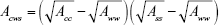
where Acws is the effective Hamaker constant for interactions across water, Aww =3.7·10−20 J is the Hamaker constant for water, while Ass =144ε. Another assumption concerns the presence of linker layer. As already found, this layer is soft and should not strongly affect the direct contact of the gold core with the CNT surface. However, we need to consider two limiting cases: 1) the presence of linker layer does not screen the interactions with the gold core, then Acc =50·10−20 J and 2) the linker layer totally screens the interactions coming from the gold core, then Acc =6.9·10−20 J, which is the typical value of the Hamaker constant for organic materials.25 This simple change of the Hamaker constant value is fully justified when the thickness of the covering layer is not smaller than 10 Å.28
The aforementioned two limiting cases are obviously little realistic, but they are easy to study. Thus, the analysis of these extreme cases helps to predict the behavior of more realistic intermediate states. Figure 7 shows the potential energy profiles obtained for various AuNP radii and CNT inner diameters adjusted in such a way that they constitute 87% of the AuNP diameter. Similar ratio was used in an experimental study12 of analogous system. The maximum studied radius of the nanoparticle was 100 Å and it corresponded to 530,000 carbon atoms creating the triple-walled nanotube.
 | Figure 7 Potential energy curves for various sizes of AuNP (a =20, 30, 50, 75, and 100 Å) interacting with triple-walled CNT (inner diameter 1.74 a) as a function of the distance. |
As shown in Figure 7, the depth of the potential energy well increases linearly with the size of the AuNP. Of course, more illustrative for analysis would be thermal averages of the interaction energy determined using eq (6). However, due to high values of the potential energy minima, the thermal averages are actually the same. The differences were observed only for small and covered by an organic layer of AuNPs. In these cases (from 20 to 50 Å AuNPs), the potential energy well depths were higher than the thermal averages by ~3–4 kJ mol−1. In other cases, thermal averages were the same as the well depths.
The energies obtained for bare nanoparticles are huge, reaching ~1,000 kJ mol−1 for 100 Å nanoparticles. This is fully understandable since Hamaker constants for metals are very high. Most probably, these energies represent an overestimation of actual values because the linker layer, though soft, might partially screen the direct interaction of the metal core with the nanotube or it might prevent the metal core from the direct contact with the CNT surface. On the other hand, we assumed the screening of the interactions due to the presence of third medium (water) between CNT and AuNP. This screening is fully justified at larger distances but at a close contact its meaning is not very clear. This is because some amount of carbon atoms belonging to the CNT can directly adhere to the metal core. This can additionally enhance the effective interaction energy but the range of the enhancement cannot be precisely determined. Thus, we can treat the energies for bare AuNPs as overestimated, but the overestimation is probably rather moderate.
The case of covered nanoparticles is definitely an underestimation of the actual interaction energy. This is because it corresponds to the situation when the linker layer acts as a stiff spacer between the CNT and the metallic core. Then, the interactions between the core and the CNT are strongly reduced and the dominant factor is the interaction of the organic layer with the CNT. Obviously, in our case of a rather soft layer of linkers such a picture is quite unlikely. However, the analysis of the limiting case allows us to predict the most probable system state and the corresponding interaction energy.
The trapping of the AuNP in the potential energy well will be thermally stable when the thermal average of the interaction energy will be significant higher than kBT. For instance, assuming that the absolute value of the energy should be at least 20 times greater than kBT (exp(−20) ~10−9), then at the temperature of 310 K it should be <−80 kJ mol−1. By looking at Figure 7, we can state that all AuNP sizes in bare nanoparticle approximation satisfy this condition. The same is with the AuNPs with radii larger than 75 Å in covered nanoparticle approximation. We can therefore conclude that detachment of AuNPs after hydrolysis of hydrazone bonds at acidic conditions cannot occur spontaneously in case of large nanoparticles. Particularly, the system studied experimentally (AuNP diameter equal to 400 Å) could not work in prescribed manner due to huge stabilizing effect coming from dispersion interactions. The linear dependence of energy on the nanoparticle size allows us to extrapolate the results to a =200 Å. It gives −277 kJ mol−1 for the covered nanoparticle approximation and −2,038 kJ mol−1 for the bare nanoparticle approximation.
Reduction of the dispersion interactions between AuNP and CNT is crucial for the uncapping process to be feasible. It seems that the only method of controlling the range of these interactions is reduction of the system size because any change of solvent properties is not possible in physiological conditions. As seen in Figure 7, lowering of the AuNP radius to 20 Å leads to energy that is in the range from −15 kJ mol−1 (covered) to −115 kJ mol−1 (bare). The true energy should be between these two limits, and perhaps it is low enough to make the system functional. However, there is another mean of controlling the dispersion interaction range. Figure 8 shows how the energy changes with the ratio between CNT and AuNP diameters.
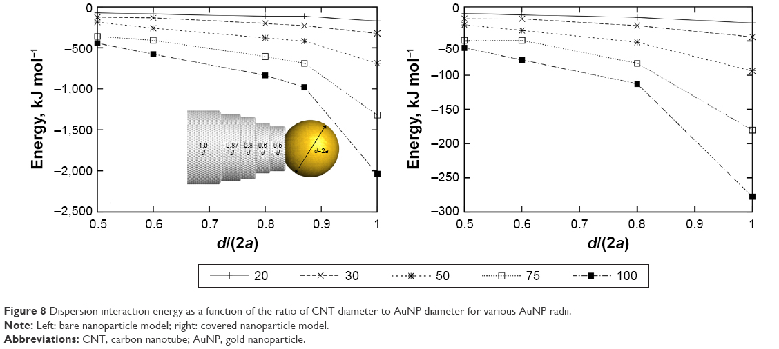 | Figure 8 Dispersion interaction energy as a function of the ratio of CNT diameter to AuNP diameter for various AuNP radii. |
As can be seen, the lowering of the ratio of CNT diameter to AuNP diameter leads to significant reduction of the dispersion interaction energy between these two objects. The results shown in Figure 7 are representative to a ratio equal to 0.87. Thus, if we reduce the CNT diameter while keeping the AuNP size unchanged, we can reduce the energy below the values, as shown in Figure 7. The range of the reduction is about double when the ratio drops from 0.87 to 0.5 for both the nanoparticle models (ie, covered or bare). Therefore, by applying not very big nanoparticles and using narrower nanotubes, we can reduce the range of dispersion interaction energy to the level that does not block the nanoparticles from the detachment. Moreover, when d/(2a) is small, then the number of linkers acting as anchors in the CNT interior will be small and, at the same time, the reduction of the anchoring effect can be achieved. Similarly, the uncapping assisted by intermolecular interactions between many nanocontainers at crowded conditions will be more effective when the diameters of AuNPs and CNT differ significantly.
Let us finally consider how structural defects of CNTs can affect the range of dispersion interactions with AuNPs. Small defects like missing carbon atoms within the CNT structure cannot significantly affect that energy. Due to a slightly lower density of carbon atoms within the interaction range with the AuNP, the dispersion interaction energy should be lower than in the case of the ideal CNT structure. Large block defects can, in turn, lead to either reduction or enhancement of the interaction energy. The reduction is expected in cases when the symmetry of the block defect does not match the symmetry of AuNP. Then, the effective number of pair interactions is lower than in the case of the ideal CNT due to the lack of good fit of AuNP surface to the block defect cavity. The enhancement of the dispersion interaction energy is, therefore, rather a rare case since it requires a good match between the symmetry of the block defect and AuNP surface. This particular case is studied in details in Figure 9 in order to estimate how strongly the dispersion interaction increases in case of a perfect match of AuNP to the block defect cavity.
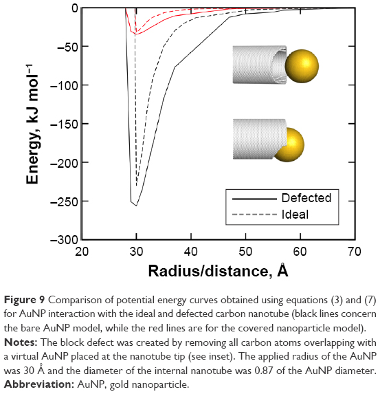 | Figure 9 Comparison of potential energy curves obtained using equations (3) and (7) for AuNP interaction with the ideal and defected carbon nanotube (black lines concern the bare AuNP model, while the red lines are for the covered nanoparticle model). |
The defected nanotube was prepared by superimposing of ideal CNT and AuNP and removing from the CNT structure all the carbon atoms that overlap with AuNP. In that way, we obtained the block defect at the CNT tip, which perfectly fits to the AuNP. Next, the potential energy curve was obtained in the same way as in the case of previous results, as shown in Figures 7 and 8. As seen in Figure 9, the depth of the potential energy curve increases when compared to the case of non-defected nanotube. However, the increase is not large as it does not exceed ~10% in this particular case of the perfect match of the defect cavity symmetry to the interacting nanoparticle. In experimental cases, such an ideal fit of the nanoparticle to the defect cavity is almost impossible. Thus, we can conclude that nonideal CNTs, which are common in experimental situations, should not produce highly enhanced dispersion interaction energy component; more likely is the reverse effect. Therefore, the lack of detachment of AuNPs at acidic conditions observed in a study by Li et al12 was not due to defected structure of CNT tips; the most likely reason was large size of systems studied experimentally.
The question thus arises: what is the optimal size of the system? The answer is quite obvious: it is the largest size for which the detachment of AuNPs at acidic conditions is still thermodynamically allowed. Then, the system would work in the desired manner and it would posses the highest possible capacity for drug molecules. However, the determination of that upper size limit is not easy. This is because the free energy changes associated with the detachment should be determined for many systems with larger and larger dimensions. Then, we could find the critical size for which the free energy barrier significantly exceeds the thermal energy. Unfortunately, such direct measurements of the free energies for larger and larger systems are computationally too expensive. Actually, the system size studied in this manuscript is the largest possible size for which the free energy can be determined within a reasonable time.
The amount of drug that can be stored and delivered in the nanotube depends on two factors: the nanotube diameter and the nanotube length. The diameter is determined directly by the system size and currently we cannot precisely state what its optimal value is. On the other hand, the nanotube length can be of any value and it can reach even micrometer scale. Therefore, it is expected that the considered system would be able to deliver large amounts of drugs. Our model system, composed of the nanotube with a diameter of 1.6 nm and length of 4 nm, is able to store at least 16 CDDP molecules and 45 water molecules together. Thus, the loading of such a narrow nanotube can be at least two CDDP molecules per 1 nm of the CNT length. In the case of a wider nanotube, but still moderately interacting with the AuNPs, the maximum loading would be much higher.
Summary and conclusion
In this work, we discussed the influence of several factors on the feasibility of the detachment of AuNPs from the CNT tips. We studied the effects resulting from interactions with another nanocontainer or with its fragment. The conclusion is that in the presence of other many atomic particles in the vicinity, the nanocontainer may facilitate the detachment of AuNPs from the CNT tips and induce the release of CDDP. This conclusion is in contradiction with experimental findings, where no detachments of gold seals were observed in the case of chemically identical system.
Further analysis focused on possible influence of such factors like the length scale, ratio of AuNP diameter to CNT diameters, or presence of block defects within the CNT structure, which helped us to find an explanation of the discrepancy between theoretical and experimental results. We found that the key factor responsible for the stability of the capped form of the nanocontainer at acidic conditions, as observed in experiment, is a huge dispersion interaction component between CNT and AuNP. This component scales linearly with the system size; thus, its reduction is possible by applying smaller AuNPs and a suitably adjusted CNT diameter. We also found that application of a smaller ratio of CNT diameter to AuNP diameter significantly reduces the dispersion interaction energy between these two objects. The presence of block defects within the CNT structure slightly enhances the dispersion interaction energy, but the effect can only appear in the case of a perfect match of the defect cavity shape and the AuNP shape, that is, rather a rare case.
Acknowledgment
This work was supported by Polish National Science Centre grant DEC-2012/07/E/ST4/00763.
Disclosure
The authors report no conflicts of interest in this work.
References
Chakraborty B, Modak P, Banerjee S. Hydrogen storage in yttrium-decorated single walled carbon nanotube. J Phys Chem C. 2012;116:22502–22508. | ||
Liu L, Nicholson D, Bhatia SK. Impact of H2O on CO2 separation from natural gas: comparison of carbon nanotubes and disordered carbon. J Phys Chem C. 2015;119:407–419. | ||
Deng Y, Zhang M, Yuan F, Li Z, Zhou W. Uniform DNA biosensors based on threshold voltage of carbon nanotube thin-film transistors. Nano. 2016;11:1650060. | ||
McSweeney RL, Chamberlain TW, Davies ES, Khlobystov AN. Single-walled carbon nanotubes as nano-electrode and nano-reactor to control the pathways of a redox reaction. Chem Commun. 2014;50:14338–14340. | ||
Takenaka S, Miyamoto H, Utsunomiya Y, Matsune H, Kishida M. Catalytic activity of highly durable Pt/CNT catalysts covered with hydrophobic silica layers for the oxygen reduction reaction in PEFCs. J Phys Chem C. 2014;118:774–783. | ||
Lalwani G, Patel SC, Sitharaman B. Two- and three-dimensional all-carbon nanomaterial assemblies for tissue engineering and regenerative medicine. Ann Biomed Eng. 2016;44:2020–2035. | ||
Rajesh R, Ravichandran YD. Development of a new carbon nanotube-alginate-hydroxyapatite tricomponent composite scaffold for application in bone tissue engineering. Int J Nanomedicine. 2015;10:7–15. | ||
Wong BS, Yoong SL, Jagusiak A, et al. Carbon nanotubes for delivery of small molecule drugs. Adv Drug Deliv Rev. 2013;65:1964–2015. | ||
Ramezanpour M, Leung SS, Delgado-Magnero KH, Bashe BY, Thewalt J, Tieleman DP. Computational and experimental approaches for investigating nanoparticle-based drug delivery systems. Biochim Biophys Acta. 2016;1858:1688–1709. | ||
Razzazan A, Atyabi F, Kazemi B, Dinarvand R. In vivo drug delivery of gemcitabine with PEGylated single-walled carbon nanotubes. Mater Sci Eng C Mater Biol Appl. 2016;62:614–625. | ||
Singh S, Mehra NK, Jain NK. Development and characterization of the paclitaxel loaded riboflavin and thiamine conjugated carbon nanotubes for cancer treatment. Pharm Res. 2016;33:1769–1781. | ||
Li J, Yoong SL, Goh WJ, et al. In vitro controlled release of cisplatin from gold-carbon nanobottles via cleavable linkages. Int J Nanomedicine. 2015;10:7425–7441. | ||
Sahoo NG, Bao H, Pan Y, et al. Functionalized carbon nanomaterials as nanocarriers for loading and delivery of a poorly water-soluble anticancer drug: a comparative study. Chem Commun (Camb). 2011;47:5235–5237. | ||
Anbarasan B, Babu SV, Elango K, Shriya B, Ramaprabhu S. pH responsive release of doxorubicin to the cancer cells by functionalized multi-walled carbon nanotubes. J Nanosci Nanotechnol. 2015;15:4799–4805. | ||
Modi CD, Patel SJ, Desai AB, Murthy RSR. Functionalization and evaluation of PEGylated carbon nanotubes as novel drug delivery for methotrexate. J Appl Pharm Sci. 2011;1:103–108. | ||
Panczyk T, Jagusiak A, Pastorin G, Ang WH, Narkiewicz-Michalek J. Molecular dynamics study of cisplatin release from carbon nanotubes capped by magnetic nanoparticles. J Phys Chem C. 2013;117:17327–17336. | ||
Panczyk T, Wolski P, Konczak L, Narkiewicz-Michalek J. Sidewall functionalization of carbon nanotubes as a method of controlling structural transformations of the magnetically triggered nanocontainer: a molecular dynamics study. J Phys Chem C. 2015;119:8373–8381. | ||
Panczyk T, Konczak L, Narkiewicz-Michalek J, Pastorin G. Corking and uncorking carbon nanotubes by metal nanoparticles bearing pH-cleavable hydrazone linkers. Theoretical analysis based on molecular dynamics simulations. J Phys Chem C. 2016;120:639–649. | ||
Tripisciano C, Kraemer K, Taylor A, Borowiak-Palen E. Single-wall carbon nanotubes based anticancer drug delivery system. Chem Phys Lett. 2009;478:200–205. | ||
Kalia J, Raines RT. Hydrolytic stability of hydrazones and oximes. Angew Chem Int Ed Engl. 2008;47(39):7523–7526. | ||
Lee CH, Cheng SH, Huang IP, et al. Intracellular pH-responsive mesoporous silica nanoparticles for the controlled release of anticancer chemotherapeutics. Angew Chem Int Ed Engl. 2010;49:8214–8219. | ||
Pastorin G. Crucial functionalizations of carbon nanotubes for improved drug delivery: a valuable option? Pharm Res. 2009;26:746–769. | ||
Lopes JF, de A Menezes VS, Duarte HA, Rocha WR, De Almeida WB, Dos Santos HF. Monte Carlo simulation of cisplatin molecule in aqueous solution. J Phys Chem B. 2006;110:12047–12054. | ||
Plimpton S. Fast parallel algorithms for short-range molecular dynamics. J Comput Phys. 1995;117:1–19. | ||
Israelachvili JN. Intermolecular and Surface Forces. Burlington, MA: Academic Press; 2011. | ||
Panczyk T, Rudzinski W, Jagusiak A. Adsorption of colloid nanoparticles on carbon nanotubes studied by means of molecular dynamics simulations. Colloids Surf Physicochem Eng Asp. 2012;409:149–158. | ||
Everaers R, Ejtehadi MR. Interaction potentials for soft and hard ellipsoids. Phys Rev E. 2003;67:041710. | ||
Panczyk T, Camp PJ, Pastorin G, Warzocha TP. Computational study of some aspects of chemical optimization of a functional magnetically triggered nanocontainer. J Phys Chem C. 2011;115:19074–19083. |
 © 2016 The Author(s). This work is published and licensed by Dove Medical Press Limited. The
full terms of this license are available at https://www.dovepress.com/terms
and incorporate the Creative Commons Attribution
- Non Commercial (unported, 3.0) License.
By accessing the work you hereby accept the Terms. Non-commercial uses of the work are permitted
without any further permission from Dove Medical Press Limited, provided the work is properly
attributed. For permission for commercial use of this work, please see paragraphs 4.2 and 5 of our Terms.
© 2016 The Author(s). This work is published and licensed by Dove Medical Press Limited. The
full terms of this license are available at https://www.dovepress.com/terms
and incorporate the Creative Commons Attribution
- Non Commercial (unported, 3.0) License.
By accessing the work you hereby accept the Terms. Non-commercial uses of the work are permitted
without any further permission from Dove Medical Press Limited, provided the work is properly
attributed. For permission for commercial use of this work, please see paragraphs 4.2 and 5 of our Terms.