Back to Journals » OncoTargets and Therapy » Volume 8
Different setup errors assessed by weekly cone-beam computed tomography on different registration in nasopharyngeal carcinoma treated with intensity-modulated radiation therapy
Authors Su J, Chen W, Yang H, Hong J ![]() , Zhang Z
, Zhang Z ![]() , Yang G, Li L, Wei R
, Yang G, Li L, Wei R
Received 23 April 2015
Accepted for publication 14 July 2015
Published 14 September 2015 Volume 2015:8 Pages 2545—2553
DOI https://doi.org/10.2147/OTT.S87159
Checked for plagiarism Yes
Review by Single anonymous peer review
Peer reviewer comments 4
Editor who approved publication: Professor Daniele Santini
Jiqing Su,1,2,* Wen Chen,2,* Huiyun Yang,2 Jidong Hong,2 Zijian Zhang,2 Guangzheng Yang,2 Li Li,2 Rui Wei2
1Department of Oncology, Changsha Central Hospital, Changsha, 2Department of Oncology, Xiangya Hospital, Central South University, Changsha, People’s Republic of China
*These authors contributed equally to this work
Abstract: The study aimed to investigate the difference of setup errors on different registration in the treatment of nasopharyngeal carcinoma based on weekly cone-beam computed tomography (CBCT). Thirty nasopharyngeal cancer patients scheduled to undergo intensity-modulated radiotherapy (IMRT) were prospectively enrolled in the study. Each patient had a weekly CBCT before radiation therapy. In the entire study, 201 CBCT scans were obtained. The scans were registered to the planning CT to determine the difference of setup errors on different registration sites. Different registration sites were represented by bony landmarks. Nasal septum and pterygoid process represent head, cervical vertebrae 1–3 represent upper neck, and cervical vertebrae 4–6 represent lower neck. Patient positioning errors were recorded in the right–left (RL), superior–inferior (SI), and anterior–posterior (AP) directions over the course of radiotherapy. Planning target volume margins were calculated from the systematic and random errors. In this study, we can make a conclusion that there are setup errors in RL, SI, and AP directions of nasopharyngeal carcinoma patients undergoing IMRT. In addition, the head and neck setup error has the difference, with statistical significance, while patient setup error of neck is greater than that of head during the course of radiotherapy. In our institution, we recommend a planning target volume margin of 3.0 mm in RL direction, 1.3 mm in SI direction, and 2.6 mm in AP direction for nasopharyngeal cancer patients undergoing IMRT with weekly CBCT scans.
Keywords: cone-beam computed tomography, setup error, PTV margins, nasopharyngeal carcinoma, intensity-modulated radiation therapy
Introduction
Nasopharyngeal carcinoma (NPC) is very common, especially, in the Southern China. Because NPC has critical structures adjacent to the tumor with high radiation sensitivity, radiation therapy (RT) remains the primary treatment modality for the locoregionally confined disease. Intensity-modulated radiotherapy (IMRT) is an advanced accurate radiotherapy technology. Recently, IMRT has become widely adopted in the treatment of NPC patients because of its ability to provide more conformal dose distributions with sharp dose gradients and to spare the surrounding organs at risk (OARs). For these advantages, it may achieve excellent local control and decrease toxicity, which will definitely improve the quality of life in patients.1–3 However, geometry and anatomic changes throughout the RT treatment course have limited the clinical benefits of IMRT.4 Some authors have reported that patients with head and neck cancer would undergo significant anatomical changes throughout a 6- to 7-week treatment course, which may be due to tumor shrinkage, weight loss, and changes of soft tissue.5,6
In recent years, several three-dimensional (3D) imaging techniques have been introduced to obtain patient’s setup errors including kilovoltage (kV) and megavoltage cone-beam computed tomography (CBCT). On-board CBCT has been adopted to resolve the critical aspects of IMRT.7–9 The CBCT using a kV imaging system mounted on a linear accelerator has become an important technique for registering patient’s setup errors.10 CBCT could minimize the systematic and random errors through offline analysis and online correction and improve the accuracy of radiotherapy; thus, we can accurately deliver radiation doses to the targets, meanwhile, protecting the surrounding normal tissue. The changes of different anatomic sites are different during the course of radiotherapy, which may not equally cause the setup errors; therefore, the security boundary setting should also be different.
Many researchers11 had reported the position errors during the course of the image-guided IMRT for head and neck cancer and determined the planning target volume (PTV) margins (MPTV) according to different position errors of each unit through the online correction or offline analysis. Mongioj et al12 analyzed the systematic and random interfractional setup errors during IMRT in 20 NPC patients by means of Electronic Portal Images Device to define appropriate PTV. A total of 578 clinical images were analyzed. Phantom data showed that the system could correct shifts with an accuracy of 1 mm, and they came to the conclusion that the PTV margin was at least 3.4 mm, 3 mm, and 3.2 mm for right–left (RL), superior–inferior (SI), and anterior–posterior (AP) directions, respectively. In a report, Wang et al13 evaluated the setup errors by using CBCT from 22 patients undergoing IMRT for NPC and found the precorrection systematic errors ranged from 1.1 mm to 1.3 mm, and the random errors were also 1.1–1.3 mm. After online correction, the systematic and random errors were 0.4–0.5 mm and 0.7–0.8 mm, respectively, in the three directions. The PTV margins for precorrection, pretreatment, and posttreatment positions were 3.5–4.2 mm, 1.6–1.8 mm, and 2.5–3.2 mm, respectively. The results showed that the CBCT-based online correction of setup errors increased the accuracy of IMRT for NPC and reduced irradiated margins by reducing the systematic error and random error at the same time. Wang et al14 obtained a total of 754 kV CBCT scanning images from 22 patients with NPC during fractionated radiotherapy, analyzed the obtained data offline, then calculated setup errors and the PTV boundary. They carried out a total of 505 scans before couch correction; the detection rates of setup errors ≤2 mm were 76.4% in RL direction, 76% in SI direction, and 85.7% in AP direction. Also, they carried out a total of 106 scans after correction. The detection rates were 97.2%, 97.2%, and 100% in RL, SI, and AP directions, respectively. And a total of 143 scans were obtained after the treatment. The detection rates were 87.4%, 87.6%, and 90% in RL, SI, and AP directions, respectively. The overall setup errors were (0.7±1.6) mm, (−0.7±1.8) mm, and (0.3±1.7) mm in the RL, SI, and AP directions, respectively, before correction and (0.4±0.8) mm, (0.3±0.8) mm, and (0±0.7) mm, respectively, after correction, and they became (0.2±1.2) mm, (0.3±1.3) mm, and (0.1±1.1) mm, respectively, after treatment. The maximum boundary of PTV was 4 mm before correction and 2.1 mm after correction. Studies showed that the kV CBCT image-guided IMRT could improve the accuracy of setup errors for NPC. Dionisi et al15 took an analysis of local positioning error of 44 patients with head and neck cancer patients with CBCT, and they found that PTV margins were 3.48 mm, 4.08 mm, and 4.33 mm in RL, SI, and AP directions, respectively, before correction. After online correction, PTV margins were <2.5 mm in all directions. It showed that a margin of 5 mm was safe in their treatment center, which also illustrated that it was effective to use kV CBCT to evaluate the accuracy of setup errors in patients with head and neck cancer.
As per our discussion, CBCT guidance is an effective modality to improve and evaluate the accuracy of IMRT for NPC patients. So far, few studies about different setup errors on different registration in patients with NPC treated with IMRT were reported.15,16 Given the importance of determining the setup errors and appropriate PTV expansion for IMRT in NPC patients, we obtained setup errors of different parts of registration, as well as the systematic and random interfraction of position errors using kV CBCT, from 30 patients with NPC. Next, we evaluated the rationality of clinical target volume (CTV)–PTV margins in our patients and determined the appropriate margin for the CTV to PTV expansion.
Materials and methods
Patient characteristics
We conducted a prospective study on setup measurement error of 30 consecutive NPC patients who were newly diagnosed in our hospital. There were 22 males and 8 females with an average age of 45 years (45±11 years). All patients with NPC were diagnosed pathologically with poorly differentiated squamous cell carcinoma. Eligible patients for this study included individuals without distant-metastatic NPC, no other dysfunction, and no <80 for Karnofsky performance status. Initial evaluation included complete patient history, physical examination, hematology and biochemistry profiles, fiberoptic nasopharyngoscopy, chest radiography, neck and nasopharynx CT and magnetic resonance imaging, abdominal sonography, and whole body bone scan using single photon emission computed tomography. All patients were staged according to 2008 nasopharyngeal carcinoma staging system in the People’s Republic of China. The authors advise that the Institutional Review Board of Xiangya Hospital deemed ethics approval was not necessary for this study, because CBCT is a generally accepted therapy to reduce setup errors for NPC patients treated with IMRT, and it does not violate ethics. Informed consent was obtained from each patient.
Radiotherapy techniques
Patients were immobilized in the supine position with EFFICAST head and shoulder thermoplastic immobilization system (MED-TEC Industries, USA), and imaging was performed on a Siemens Plus4 Spiral CT simulator for 3 mm slice thicknesses. The scan started from the vertex to manubriosternal joint. The CT datasets were transferred to the Varian Eclipse treatment planning system through DICOM network.
Target delineation and treatment planning
The target delineation in NPC patients was contoured on the axial slices of the planning CT scan by one oncologist and approved by another oncologist. According to the International Commission on Radiation Units and Measurements reports 50 and 62,17,18 the primary gross volume (GTVnx) and the involved lymph nodes (GTVnd) were delineated as all known gross lesions shown in the enhanced CT images and/or magnetic resonance imaging images. CTV1 was defined as the high-risk regions surrounding the primary tumor and all the neck nodes at high risk, while CTV2 was defined as the low-risk node region below the CTV1. The PTVs and planning OAR volumes were generated by adding a 3-mm margin to the respective CTVs and corresponding structures such as the bilateral parotids, spinal cord, and brainstem.
All the IMRT plans were created on the Varian Eclipse treatment planning system (Varian Industries, USA) using nine coplanar beams with 6 MV photons. And the prescribed dose was 71.94–73.92 Gy in 33 fractions delivered to GTVnx and 69.96 Gy in 33 fractions delivered to GTVnd, while PTV1 received 60.06–64.35 Gy in 33 fractions and PTV2 received 50.96–56.18 Gy in 28 fractions. Doses of OARs were subject to the following restrictions: brain stem, 54 Gy, spinal cord, 45 Gy, and at least 50% of the parotids, 30–35 Gy. All patients were treated with one fraction daily for 5 days per week. Treatment was delivered on a 6-MV linear accelerator once the physician and physicist have approved the treatment planning together.
Image-guided radiotherapy procedure
Setup and CBCT guidance protocol
The kV CBCT images were obtained on a weekly basis after conventional positioning by aligning the in-room lasers with the marks on the thermoplastic masks. The pretreatment kV CBCT scan was acquired using the VARIAN On-board Imaging Systems linear accelerator equipped with kV imaging capabilities (VARIAN On-board Imaging Systems, USA), using the following parameters: kVp, 100 kV; nominal milliamperes per frame, 10 mA; nominal milliseconds, 10 ms; kV collimator, s20; kV filter, f0; approximate frames, 361; and total angle, 200. Images were then obtained by using 3D/3D Match pattern. The parameters were as follows: diameter and length of the scan field of view of head and neck, 18 cm and 14 cm; mage reconstruction matrix, 512×512; and reconstruction slice thickness, 3 mm. During the course of the treatment, each patient underwent a weekly kV CBCT scanning before radiotherapy. Setup corrections were made before treatment if the translational setup error was greater than 3 mm in any direction. In total, we obtained 201 images in this study.
CBCT image registration
We analyzed all the acquired images online using VARIAN On-board Imaging Systems software to register the CBCT scan to the planning CT scan by automatic bone matching with combination automatic registration and manual fine-tuning method for image registration. Different bony landmarks represent different regions: nasal septum and pterygoid process represents head, cervical vertebrae 1–3 represent upper neck, and cervical vertebrae 4–6 represent lower neck (Figures 1–3). We compared the setup deviation of kV CBCT image and CT image registration collected in different regions and recorded the figures of setup errors of three translational directions such as RL, SI, and AP directions. Then we compared the differences among the three different regions (head, upper neck, lower neck) of image registration results.
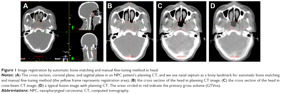 | Figure 1 Image registration by automatic bone matching and manual fine-tuning method in head. |
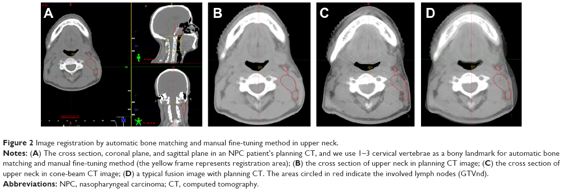 | Figure 2 Image registration by automatic bone matching and manual fine-tuning method in upper neck. |
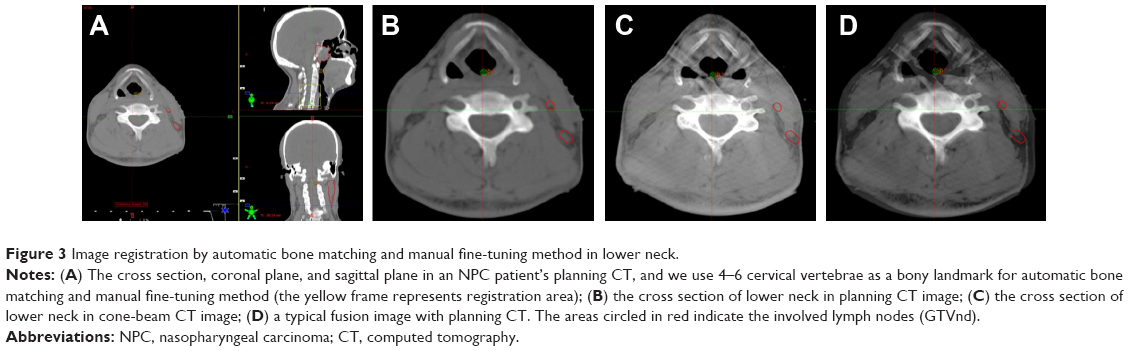 | Figure 3 Image registration by automatic bone matching and manual fine-tuning method in lower neck. |
Statistical analysis and determination of PTV margins
The data were analyzed with SPSS software, version 19.0 (IBM Corporation, Armonk, NY, USA). According to the Stroom definition of the error estimation method:19 the mean value of each patient’s position error is individual systematic errors, and the standard deviation (SD) of each patient’s position error is individual random errors; while group systematic errors (Σ) is the SD of the individual systematic errors, and random errors (σ) is the SD of the individual random errors. Setup errors can be expressed by the systematic errors ± random errors (Figure 4). We used one-way analysis of variance (ANOVA) to analyze the difference of setup errors among head, upper neck, and lower neck prior to corrections or treatment. We carried out the ANOVA or Kruskal–Wallis H-test, then used Nemenyi test to make multiple comparison among head, upper neck, and lower neck. Differences were considered statistically significant when P<0.05. According to the classical van-Herk formula MPTV =2.5Σ +0.7σ, we estimated the ideal CTV-to-PTV margins (MPTV).
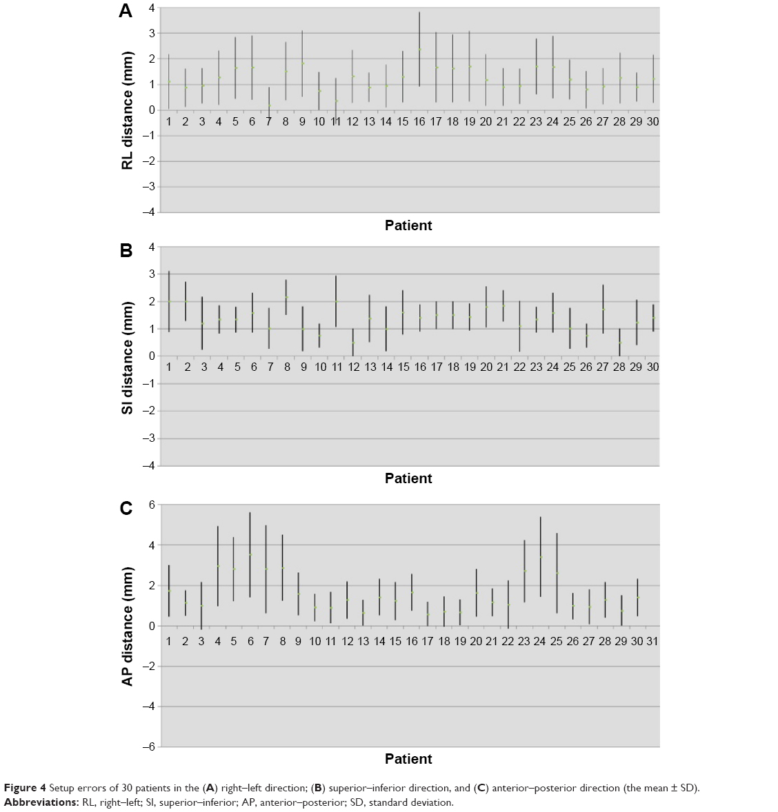 | Figure 4 Setup errors of 30 patients in the (A) right–left direction; (B) superior–inferior direction, and (C) anterior–posterior direction (the mean ± SD). |
Results
The measurement results of setup errors and PTV margins
A total of 201 position verification scans were acquired and analyzed. For the translational shifts, we use these images to compare with the corresponding planning CT and measure the deviation of bone reference points in RL, SI, and AP directions. The results were as follows: 1) the deviation of bony reference points in the head were in the range of 0–3 mm in RL and AP directions, while 0–4 mm in SI direction; the frequencies of setup errors >3 mm in SI direction were 2 (0.5%). 2) The deviation of bony reference points in the upper neck were in the range of 0–5 mm, 0–4 mm, and 0–6 mm in RL, SI, and AP directions, respectively; the frequencies of setup errors >3 mm in RL, SI, and AP directions were 8 (1.3%), 3 (0.5%), and 36 (6.0%), respectively. 3) The deviation of bony reference points in the lower neck were in the range of 0–6 mm, 0–4 mm, and 0–9 mm in RL, SI, and AP directions, respectively; the frequencies of setup errors >3 mm in RL, SI, and AP directions were 56 (9.3%), 3 (0.5%), and 153 (25.4%), respectively (Table 1). According to the Stroom definition of the error estimation method, we could come to a conclusion that the group systematic errors and random errors were 0.708 mm and 1.407 mm in RL direction, respectively; the group systematic errors and random errors were 0.433 mm and 0.189 mm in SI direction, respectively; and the group systematic errors and random errors were 0.896 mm and 0.504 mm in AP direction, respectively (Table 2). According to the classical van-Herk formula MPTV =2.5Σ +0.7σ, we figured out the ideal PTV margins (MPTV) based on the setup errors. Considering the setup errors and the accuracy of deliver radiation doses to the targets and their surrounding normal structures, margins of 2.788 mm, 1.215 mm, and 2.593 mm were required in the RL, SI, and AP directions, respectively (Table 2).
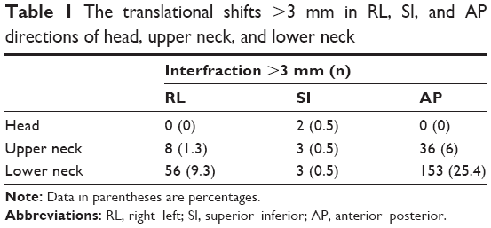 | Table 1 The translational shifts >3 mm in RL, SI, and AP directions of head, upper neck, and lower neck |
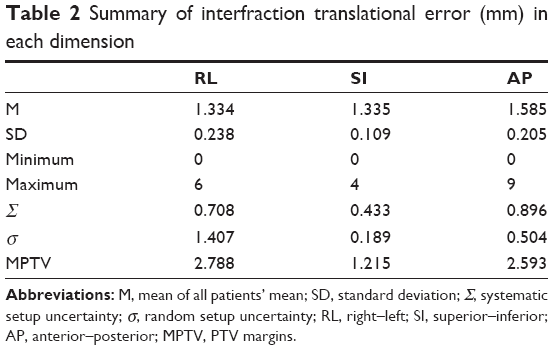 | Table 2 Summary of interfraction translational error (mm) in each dimension |
ANOVA of setup errors in different parts
We treated nasal septum and pterygoid process as head, cervical vertebrae 1–3 as upper neck, and cervical vertebrae 4–6 as lower neck. We first used one-way ANOVA to compare the setup errors among head, upper neck, and lower neck in RL, SI, and AP directions. We came to the conclusion that the setup errors among head, upper neck, and lower neck in SI directions were with homogeneity (P>0.05); hence, we should conduct the ANOVA; the setup errors with head, upper neck, and lower neck in RL and AP directions were not with homogeneity (P<0.05), so we could use Kruskal–Wallis H-test. The results were shown in Table 2. In RL and AP directions, the setup errors had statistical significance among head, upper neck, and lower neck (P=0.000, P=0.000) and the setup errors were not all the same; in SI direction, no statistical significance of setup errors were found among head, upper neck, and lower neck (P=0.982) (Table 3).
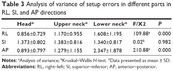 | Table 3 Analysis of variance of setup errors in different parts in RL, SI, and AP directions |
Then we use Nemenyi test to take multiple comparison among head, upper neck, and lower neck in all the 30 NPC patients in RL and AP directions. The setup errors in RL and AP directions both had statistical significance in the multiple comparisons among these three regions of interest (ROIs). The setup errors in lower neck were the greatest, and the setup errors in upper neck were greater than those in the head.
Discussion
The dose distribution of IMRT in NPC patients is completely based on the volume data of pretreatment CT, which just present the anatomical structure of the patients at this moment, but it does not take into account the daily changes in patients with target volumes, OARs, and the anatomical location.20 The steep dose gradient between the structures may mean that this will increase the risk of lower dose in primary tumor and overdose to adjacent normal structure. The setup errors have a large impact on IMRT plan due to its sharp dose gradient.13,21 When the setup errors exist, even a very small deviation of isodose shift may cause significantly decreased doses to target volumes and increase doses to OARs during the long course of IMRT treatment. So that the targets do not have enough dose irradiation, which leads to local recurrence of tumor, and the overdose irradiation to normal tissue increases the complications significantly. During the course of IMRT, treatment accuracy may decrease with time due to tumor regression or changes of target position and anatomical structure. All of these uncertain factors will affect the actual irradiation dose distribution of planning targets. Because the motion range of anatomical areas in everyone is different, monitoring the motion range and motion rule personally, guiding radiotherapy planning according to their change, reducing setup errors, and ensuring accurate implementation of radiotherapy have a very important meaning for every NPC patient, which also become the research priorities for physicians, physicists, and technicians in the present RT field. Hence, to take full advantage of IMRT, image-guided radiation therapy (IGRT) becomes an important means for radiotherapy. IGRT is a new radiotherapy technology after 3D-CRT and IMRT; it combines RT machine and imaging equipment, collects images and other signals in fractionated radiotherapy and treatment, and then guides the treatment and follow-up treatment.7,22
There are few reports about the difference of setup errors between head and neck during the course of kV CBCT-guided IMRT for NPC patients. Due to the universality of neck lymph node metastasis in patients with NPC, the neck region is one of the most important radiation regions. Any deformation or movement of the neck is closely related with dose distribution to brain stem, spinal cord, and other surrounding structures. Therefore, we should pay full attention to the setup errors of the neck, and it is also very important to notice the difference of setup errors between head and neck.
Ove et al23 reported that when using rail CT to perform position verification, low neck cervical spine point was displaced an average of 3.08±0.17 mm anteriorly, and there was no systematic lateral or craniocaudal displacement. The SD of random setup errors was 3.3 mm, 2.6 mm, and 3.9 mm in RL, SI, and AP directions in low neck, respectively. Results show that the varied change of low neck position was excess of the planning margins. There was a systematic anterior displacement in the lower cervical neck, and the random setup errors were larger than expected. So we should delineate a larger planning boundary in the neck area.
van Kranen et al24 took a regular CBCT scan in 38 cases of head and neck cancer patients to quantify local geometrical uncertainties in anatomical subregions for offline patient setup correction. By local rigid registration to successive CBCT scans, the local setup accuracy of each ROI was determined and compared with the overall setup error assessed with the large ROI. They found that local setup errors were larger than the overall setup error during the treatment, ranging from 1.1 mm to 3.4 mm (systematic) and 1.3 mm to 2.5 mm (random). These data are consistent with Polat et al25 who pointed out that local setup errors were large, so the current PTV may not be sufficient to account for these uncertainties; therefore they proposed registration of multiple ROIs to drive correction protocols and adaptive radiotherapy to reduce the impact of local setup variations.
Zhang et al26 took an analysis of 3D setup uncertainties for multiple ROIs in head and neck region. Three separate bony ROIs were defined: C2 and C6 vertebral bodies and the palatine process of the maxilla. They used a CT-on-rails system to take in-room CT scans for 14 patients and found that noticeable differences ~2–6 mm existed between any two ROIs, indicating the flexibility and/or rotational effect in the head and neck region. The neck region (C6) had the largest RL shifts. This is also consistent with the conclusion that the lower neck had larger setup errors. Their study concluded that there is variability in setup corrections for different regions of head and neck anatomy. So we should consider these relative positional variations when making setup corrections or designing treatment margins. From these studies, we can make the conclusion that we should not treat the setup errors of head as consistent with neck, and we should not take a uniform external expansion for CTV to PTV. We should formulate the corresponding reasonable expansion spacing, or use a more advanced technology to reduce the setup errors.
There are several reasons that may cause greater errors in the neck setup than in the head setup: 1) patients with oral mucositis during radiotherapy lose appetite, which leads to weight loss, and the size of the neck is more likely to become smaller because there is more subcutaneous adipose tissue in the neck. 2) The neck diameter is reduced after the huge cervical lymph nodes are significantly reduced during radiotherapy. 3) Because of these reasons, the mask becomes loose, which makes the neck move more in the RL direction than the AP direction. 4) There appears to be different degrees of radioactive dermatitis in the neck during the late course of radiotherapy, and so when in contact with the head and shoulder mask, the patient will nonautonomically move the body because of pain, which will cause the change of position.
The difference of setup errors of head and neck for NPC with IMRT has important clinical significance: 1) with application of IGRT combined with IMRT, we could monitor changes in patients daily or weekly, find errors timely, and make an online correction. 2) The neck is more flexible than the head, which calls for it to be better fixed to further reduce setup errors during radiotherapy for patients with head and neck cancer.27 3) The shrinking of cervical lymph node can cause a dramatic change of the contour, so we can modify the target area and adjust the treatment plan to reduce the risk of overdosage to spinal cord and skin. 4) We should take an active prevention and treatment of oral mucositis during the treatment, patients should be encouraged to eat or take parenteral nutrition to maintain body weight. 5) We should pay full attention to radioactive dermatitis and reduce the head and neck motion caused by discomfort during the treatment, and we should temporarily stop the radiotherapy in severe lesions. 6) Each radiotherapy unit should determine the CTV-to-PTV margin according to the actual situation. We should distinguish the head and neck to provide accurate expanding boundary value to patients during radiotherapy.
In our study, we use kV CBCT-guided IMRT from 30 NPC patients. The CBCT scans were registered to the planning CT to determine the difference of setup errors on head, upper neck, and lower neck. Then we make a multiple comparison between these three different registration sites. From our data, we also got the setup errors in RL, SI, and AP directions. As van Kranen et al24 pointed out that head and neck cancer patients have considerable local setup variations, exceeding overall patient setup uncertainty in an offline correction protocol. Therefore, we propose registration of multiple ROIs to drive correction protocols, which allowed us to evaluate the proper PTV margin. Overall, our results were comparable with the previous research. There are also some shortcomings in our study. We did not take a daily CBCT for every patient because of different economic situations of every patient and hospital resource utilization. Our study suggest that a PTV margin of 3.0 mm, 1.3 mm, and 2.6 mm in RL, SI, and AP directions for NPC patients is acceptable when weekly CBCT was used. We should draw such a conclusion carefully since all patients in our research were treated with a uniform nonreduced PTV margin. Further investigation should focus on the impact of weekly CBCT with a reduction PTV margin on clinical outcomes.
Thus, we could use CBCT to take repeated scanning during IMRT in NPC patients to find different setup errors between head and neck, because of the difference of patients, hospital devices, technologies, and other aspects, we should analyze the data according to the actual circumstances of each treatment center.
Conclusion
There are setup errors in RL, SI, and AP directions of NPC patients undergoing IMRT. Patient’s setup errors of neck are greater than the head during the course of radiotherapy. From this study, we recommend a PTV margin of 3.0 mm, 1.3 mm, and 2.6 mm in RL, SI, and AP directions for NPC patients undergoing IMRT in our institution. Repeat CT scan and re-planning should be necessary during the course of the treatment.
Acknowledgments
This study was supported by a grant (number 2012FJ4321) from the Department of Science and Technology of Hunan Province of China and Hunan High-Tech Development and Reform Commission (2012 number 1493).
Disclosure
The authors report no conflicts of interest in this work.
References
Zhong H, Chen G, Lin D, Chen G. Comparison of side effects of intensity modulated radiotherapy and conventional radiotherapy in 69 cases with nasopharyngeal carcinoma. Lin Chung Er Bi Yan Hou Tou Jing Wai Ke Za Zhi. 2013;27:462–464. | ||
Peng G, Wang T, Yang KY, et al. Aprospective, randomized study comparing outcomes and toxicities of intensity-modulated radiotherapy vs. conventional two-dimensional radiotherapy for the treatment of nasopharyngeal carcinoma. Radiother Oncol. 2012;104:286–293. | ||
Zhang Y, Lin ZA, Pan JJ, et al. Concurrent control study of different radiotherapy for primary nasopharyngeal carcinoma: intensity-modulated radiotherapy versus conventional radiotherapy. Ai Zheng. 2009;28:1143–1148. | ||
Han CH, Chen YJ, Liu AL, Schultheiss TE, Wong JY. Actual dose variation of parotid glands and spinal cord for nasopharyngeal cancer patients during radiotherapy. Int J Radiat Oncol Biol Phys. 2008;70:1256–1262. | ||
Barker JL Jr, Garden AS, Ang KK, et al. Quantification of volumetric and geometric changes occurring during fractionated radiotherapy for head-and-neck cancer using an integrated CT/linear accelerator system. Int J Radiat Oncol Biol Phys. 2004;59:960–970. | ||
Zhang X, Li M, Cao J, et al. Dosimetric variations of target volumes and organs at risk in nasopharyngeal carcinoma intensity-modulated radiotherapy. Br J Radiol. 2012;85:e506–e513. | ||
Boda-Heggemann J, Lohr F, Wenz F, Flentje M, Guckenberger M. kVcone-beam CT-based IGRT: a clinical review. Strahlenther Onko. 2011;l187:284–291. | ||
Pouliot J, Bani-Hashemi A, Chen J, et al. Low-dose megavoltage cone-beam CT for radiation therapy. Int J Radiat Oncol Biol Phys. 2005;61:552–560. | ||
Létourneau D, Wong JW, Oldham M, et al. Cone-beam-CT guided radiation therapy: technical implementation. Radiother Oncol. 2005;75:279–286. | ||
Chau RM, Teo PM, Kam MK, Leung SF, Cheung KY, Chan AT. Dosimetric comparison between 2-dimensional radiation therapy and intensity modulated radiation therapy in treatment of advanced T-stage nasopharyngeal carcinoma: to treat less or more in the planning organ-at-risk volume of the brainstem and spinal cord. Med Dosim. 2007;32:263–270. | ||
Lu H, Lin H, Feng G, et al. Interfractional and intrafractional errors assessed by daily cone-beam computed tomography in nasopharyngeal carcinoma treated with Intensity modulated radiation therapy: a prospective study. J Radiat Res. 2012;53:954–960. | ||
Mongioj V, Orlandi E, Palazzi M, et al. Set-up errors analyses in IMRT treatments for nasopharyngeal carcinoma to evaluate time trends, PTV and PRV margins. Acta Oncol. 2011;50:61–71. | ||
Wang J, Bai S, Chen N, et al. The clinical feasibility and effect of online cone beam computer tomography-guided intensity-modulated radiotherapy for nasopharyngeal cancer. Radiother Oncol. 2009;90:217–221. | ||
Wang J, Xu F, Bai S, et al. Preliminary application of kilo-volt cone-beam computed tomography to intensity-modulated radiotherapy of nasopharyngeal carcinoma. Ai Zheng. 2008;27:761–765. | ||
Dionisi F, Palazzi MF, Bracco F, et al. Set-up errors and planning target volume margins in head and neck cancer radiotherapy: a clinical study of image guidance with on-line cone-beam computed tomography. Int J Clin Oncol. 2012;18:418–427. | ||
Prabhakar R, Laviraj MA, Haresh KP, Julka PK, Rath GK. Impact of patient setup error in the treatment of head and neck cancer with intensity modulated radiation therapy. Phys Med. 2010;26:26–33. | ||
International Commission on Radiation Units and Measurements (ICRU). ICRU Report 50: Prescribing, Recording, and Reporting Photon Beam Therapy. Bethesda, MD: ICRU; 1993. | ||
International Commission on Radiation Units and Measurements (ICRU). ICRU Report 62: Prescribing, Recording, and Reporting Photon Beam Therapy (Supplement to ICRU Report 50). Bethesda, MD: ICRU; 1999. | ||
Stroom JC, Heijmen BJ. Geometrical uncertainties, radiotherapy planning margins, and the ICRU-62 report. Radiother Oncol. 2002;64:75–83. | ||
Tan W, Li Y, Han G, et al. Target volume and position variations during intensity-modulated radiotherapy for patients with nasopharyngeal carcinoma. OncoTargets and Therapy. 2013;6:1719–1728. | ||
Hong TS, Tomé WA, Chappell RJ, Chinnaiyan P, Mehta MP, Harari PM. The impact of daily setup variations on head-and-neck intensity-modulated radiation therapy. Int J Radiat Oncol Biol Phys. 2005;61(3):779–788. | ||
Ling CC, Yorke E, Fuks Z. From IMRT to IGRT: frontierland or neverland? Radiother Oncol. 2006;78:119–122. | ||
Ove R, Cavalieri R, Noble D, Russo SM. Variation of neck position with image-guided radiotherapy for head and neck cancer. Am J Clin Oncol. 2012;35:1–5. | ||
van Kranen S, van Beek S, Rasch C, van Herk M, Sonke JJ. Setup uncertainties of anatomical sub-regions in head-and-neck cancer patients after offline CBCT guidance. Int J Radiat Oncol Biol Phys. 2009;73:1566–1573. | ||
Polat B, Wilbert J, Baier K, Flentje M, Guckenberger M. Nonrigid patient setup errors in the head-and-neck region. Strahlenther Onkol. 2007;183:506–511. | ||
Zhang L, Garden AS, Lo J, et al. Multiple regions-of-interest analysis of setup uncertainties for head-and-neck cancer radiotherapy. Int J Radiat Oncol Biol Phys. 2006;64:1559–1569. | ||
Li H, Zhu XR, Zhang L, et al. Comparison of 2D radiographic images and 3D cone beam computed tomography for positioning head-and-neck radiotherapy patients. Int J Radiat Oncol Biol Phys. 2008;71:916–925. |
 © 2015 The Author(s). This work is published and licensed by Dove Medical Press Limited. The
full terms of this license are available at https://www.dovepress.com/terms
and incorporate the Creative Commons Attribution
- Non Commercial (unported, 3.0) License.
By accessing the work you hereby accept the Terms. Non-commercial uses of the work are permitted
without any further permission from Dove Medical Press Limited, provided the work is properly
attributed. For permission for commercial use of this work, please see paragraphs 4.2 and 5 of our Terms.
© 2015 The Author(s). This work is published and licensed by Dove Medical Press Limited. The
full terms of this license are available at https://www.dovepress.com/terms
and incorporate the Creative Commons Attribution
- Non Commercial (unported, 3.0) License.
By accessing the work you hereby accept the Terms. Non-commercial uses of the work are permitted
without any further permission from Dove Medical Press Limited, provided the work is properly
attributed. For permission for commercial use of this work, please see paragraphs 4.2 and 5 of our Terms.