Back to Journals » Medical Devices: Evidence and Research » Volume 11
Comparison of a micro-electro-mechanical system airflow sensor with the pneumotach in the forced oscillation technique
Authors Xu XK, Harvey BP ![]() , Lutchen KR, Gelbman BD, Monfre SL
, Lutchen KR, Gelbman BD, Monfre SL ![]() , Coifman RE
, Coifman RE ![]() , Forbes CE
, Forbes CE ![]()
Received 24 July 2018
Accepted for publication 9 October 2018
Published 13 December 2018 Volume 2018:11 Pages 419—426
DOI https://doi.org/10.2147/MDER.S181258
Checked for plagiarism Yes
Review by Single anonymous peer review
Peer reviewer comments 2
Editor who approved publication: Dr Scott Fraser
Xiaohe K Xu,1 Brian P Harvey,2 Kenneth R Lutchen,2 Brian D Gelbman,3 Stephen L Monfre,1 Robert E Coifman,1 Charles E Forbes1
1Feather Sensors, LLC, Millville, NJ 08332, USA; 2Department of Biomedical Engineering, Boston University, Boston, MA 02215, USA; 3Division of Pulmonary and Critical Care Medicine, Weill Cornell Medical Center, New York, NY 10065, USA
Purpose: This study supports the use of thin-film micro-electro-mechanical system (MEMS) airflow sensors in the forced oscillation technique.
Materials and methods: The study employed static testing using air flow standards and computer-controlled sound attenuations at 8 Hz. Human feasibility studies were conducted with a testing apparatus consisting of a pneumotach and thin-film MEMS air flow sensors in series. Short-time Fourier transform spectra were obtained using SIGVIEW software.
Results: Three tests were performed, and excellent correlations were observed between the probes. The thin-film MEMS probe showed superior sensitivity to higher frequencies up to 200 Hz.
Conclusion: The results suggest that lower-cost thin-film MEMS can be used for forced oscillation technique applications (including home care devices) that will benefit patients suffering from pulmonary diseases such as asthma, COPD, and cystic fibrosis.
Keywords: pulmonary disease, pulmonary impedance, airway resistance, short-time Fourier transform, glottis closure
Plain language summary
Airflow probes based on a thin-film micro-electro-mechanical system (MEMS) sensor have been evaluated for use as a replacement for the pneumotach in the forced oscillation technique (FOT). A pneumotach and a probe containing a thin-film MEMS sensor were mounted in series, and data were simultaneously collected from both airflow sensors and compared to a common pressure sensor. Static experiments using a computer to control sound levels as well as experiments using airflow resistors indicated nearly similar responses for both sensors. Dynamic FOT experiments using human subjects as the impedance load indicated a high correlation (R2=0.990) between the pneumotach and the thin-film MEMS sensor. Data comparing the frequency response of a commercially available pneumotach with a thin-film MEMS probe indicated that the MEMS probe was more sensitive to higher frequencies (200 Hz).
Introduction
This study examines the use of thin-film micromechanical sensors as airflow detectors in the pulmonary forced oscillation technique (FOT). The FOT was first introduced by Dubois et al1 in 1956, which provides airflow impedance measurements of the lung that are useful for the management of respiratory diseases. FOT imposes an oscillating external pressure (about ±2 cm H2O) at frequency Ω to the airways of the subject and monitors the oscillatory output from two independent sensors corresponding to pressure and flow.2 Typically, a loud speaker is used to generate the pressure oscillation at a frequency (4–32 Hz) that is much higher than the patients’ breathing rate (≤1 Hz). The mechanical oscillatory impedance of the lung function is measured, analogous to resistance/inductance/capacitance in electrical systems, providing information on the complex impedance, Z (Ω), as well as the resistive (in-phase), R (Ω), and the reactance (out-of-phase), X (Ω), components.3 Due to its non-invasive characteristic, FOT has become an important clinical technique for evaluating lung health, particularly in infants, young children, or incapacitated patients who are unable to execute the forceful breathing procedures required in techniques such as spirometry.
The flow sensor typically used for conventional FOT is the pneumotachograph or pneumotach, the current GOLD standard for airflow measurement in pulmonary science.2 The pneumotach sensor has excellent linear characteristics and a stable baseline. Pneumotachs utilize either a screen or a honeycomb arrangement of small tubes in the airflow conduit and have a differential pressure transducer connected to pressure taps before and after the screen (or tubes). The devices are widely used in pulmonary spirometers and ventilators. However, pneumotachs are also rather expensive, and, to improve sensitivity, large diameter screens or honeycombs are needed to enhance low flow responses. The resistive elements of pneumotachs are also difficult to clean and disinfect, and they require daily or more frequent calibration, as their calibration varies with barometric pressure. They are sensitive to condensation from human breath, requiring additional heating elements for many applications. Their accuracy,4,5 calibration procedures,6 and frequency response7 have been studied over the past six decades.
This study examined an alternative method of measuring airflow based on the mechanical movement of a flexible thin-film micro-electro-mechanical system (MEMS) device oriented perpendicular to the airflow in the conduit.8 The sensor studied consists of the MEMS element on the surface of a flexible polyimide film that is sensitive to bending due to airflow. This mechanical sensing system has biological counterparts in structures such as cilia and fins.9 An attractive feature of thin-film MEMS devices is their improved frequency response compared to pneumotachs. Our motivation for this study was the development of light weight, lower cost, portable home oscillatory devices that can be used in the management of lung diseases such as asthma,10 COPD,11 and cystic fibrosis.12
Materials and methods
Thin-film MEMS sensor fabrication
Conventional photolithography was used to pattern the serpentine MEMS structures on the surface of the 51 µm polyimide film. The serpentine structure was oriented parallel to the film providing the best signal when the film is bent during airflow. Prior to metallization, the film substrate was heated at elevated temperatures (115°C) for a short time (5–10 minutes) to improve adhesion. An Angstrom Engineering’s Three Source Magnetron (Angstrom Engineering Inc., Kitchener, ON, Canada) was used to sputter 5 nm thick Cr and 400 nm thick Au layers on the film in high vacuum. Deposition times were several hours. When the sample was removed from the instrument, lift-off was performed using photolithography, acetone ultrasonic cleaning, followed by an isopropyl alcohol rinse. Fabricated sensors showed excellent adhesion of the metal layer to the substrate and passed the ASTM D3359-17 tape peel test. The MEMS films were also tested with dynamic stressing tests (Ω=4–200 Hz) using the woofer and MEMS sensor as shown in Figure 1. Dynamic stressing tests were performed for at least 24 hours for monitoring the constancy of peak height during the experiments.
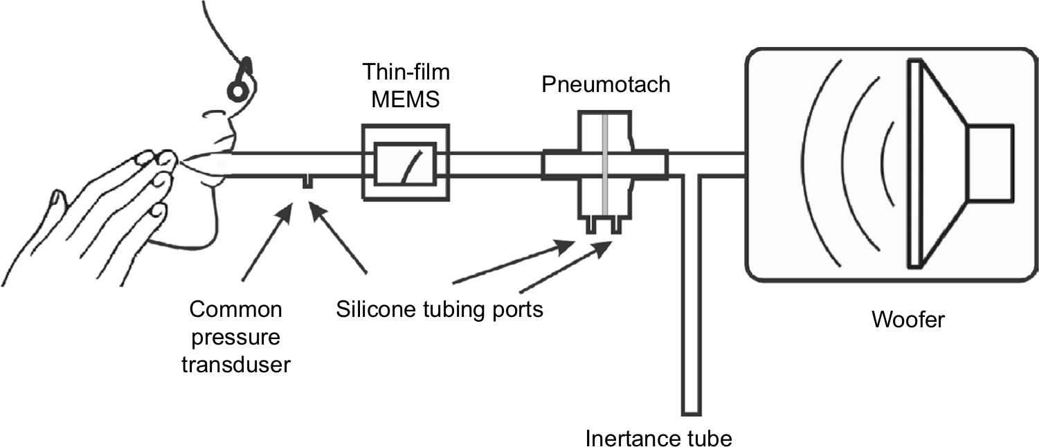 | Figure 1 Test apparatus used for the dynamic oscillatory studies. Notes: A 10” sub-woofer produced forced pressure 8 Hz oscillations. A differential pressure transducer was used to measure pressure fluctuations. Flow was measured simultaneously with a thin-film sensor and a screen pneumotach. An inertance tube provided a renewed air supply to the subject as well as a resistive element needed to pressure balance the system. |
Thin-film probe construction
Prototype housings were constructed using balsa wood, since this is an easily worked material. Channels in a block of balsa (2˝×2˝×3˝) were machined using a router with straight bit shapes. The channel was sanded to remove stray filaments of wood on the side walls. Cyanoacrylate was used to seal the surfaces in the air chamber affording (after light sanding) smooth surfaces. Temporary paper stock spacers were used to position the sensor in the channel to ensure a tight fit with free movement after construction. Two separate pieces were placed on the top of the channel to firmly attach the sensor at the base. End caps were constructed from balsa and plywood using a ¾˝ Foster bit to allow ¾˝ airflow tubing to be attached. Cyanoacrylate glues of varying viscosities were used to seal the housing during the construction process. The finished structure was a rectangular box (2˝×2˝×4˝) with the channel running along the long axis (Figure 1). A two wire 1/8” phone jack was used for electrical connection to pads on the thin-film MEMS structure. Resistance of the thin-film sensor was measured with an external Wheatstone bridge coupled with a Texas Instrument TI INA122PA operational amplifier (Texas Instruments Inc., Dallas, TX, USA).
Pneumotach, pressure sensors, and resistance standards
The pneumotach, a 4700 Series Hans Rudolph 0-160 LPM (Hans Rudolph Inc., Shawnee, KS, USA), was coupled with an Alpha Instruments Differential Pressure Model: 164W0001BC2YAA sensor (Servoflo Corporation, Lexington, MA, USA) using silicone tubing connected to the two pneumotach ports. The pressure sensor was connected to a second Alpha Instrument Differential Pressure Sensor connected singly to the instrument assembly with a silicone tube; the second port of the pressure sensor was vented to the atmosphere. The thin-film MEMS sensor was placed in series with the pneumotach. This study used an experimental configuration with both sensors in series (Figure 1). For the steady state experiments, no load was present, or Hans Rudolph Flow Resistance Standards, linear type, available in standard ranges of 5, 20, 50, 200, 500, and 1000 cm H2O s/L, were employed.
The MATLAB software code (MathWorks, Natick, MA, USA) for the recursive least squares (RLS) algorithm was based on the algorithm developed by Jensen et al13 The MATLAB Butterworth function (four pole) was used for the high pass filter with a cutoff frequency of 4 Hz. The forgetting factor for this calculation was set at 0.78, which, at 40 data points/second, sets the time constant to 0.1 seconds.14
Short-time Fourier transform (STFT)
STFT scans were accomplished with Sigview software using the microphone channel of a computer as the input from either the pneumotach or thin-film MEMS sensors. Sigview is a real-time signal analysis software package available from SignalLab that uses the sound card to monitor the output from the operational amplifiers (SignalLab e.K., Pforzheim, Germany). Frequency scans, using the sub-woofer speaker as the sound source, were made starting at 2 Hz and scanning to 250 Hz in 30 seconds, followed by multiple Fourier analyses over short time intervals compared to the frequency scan. The relative intensity of the impedance, Z, is plotted on the z-axis and the frequency and time are plotted in the x–y plane.
Computational
A single ADC (analog-to-digital converter DI-1100; DATAQ Instruments Inc., Akron, OH, USA) simultaneously collected the data into [FPneumotachFThin-FilmPPressure] sets where F represents airflow and P represents pressure. Since the pressure data are common to both the flow sensors, the data are separated into two components: 1) pneumotach and 2) thin-film MEMS. A digital high-pass filter (four-pole Butterworth) was used to remove unwanted effects from tidal breathing and heart rate for the subjects at rest.
We assumed a linear model to the systems and apply RLS methodology13–17 to obtain a phase space for the dynamical system (8 Hz) under study. RLS is a fast recursive algorithm, first introduced by Avanzolini et al,14 that examines data in the past and computes updated parameter estimates as new data arrive, allowing almost real-time calculations of Z. Each flow sensor required its own phase correction factor, θ, applied as a phase shift to the complex Z data.
Results
Steady state experiments
Two steady state studies were conducted to test the thin-film probe response vs that of the commercial pneumotach. The basic setup (Figure 1) was used, except that the subject was replaced with either no load, or a series of known airflow resistors. The oscillatory responses for both the pneumotach and thin-film sensors are plotted against the attenuation (dB) of the 8 Hz signal sent to the speaker and as a function of the standard Hans Rudolph airflow resistors (Figure 2A and B). Both the sensors gave smooth and nearly identical responses. In both the experiments, the thin-film sensor showed a higher response at high flow conditions; at lower flow, the pneumotach showed a slightly higher response. Both the sensors were demonstrated to cover the frequency ranges of interest.
 | Figure 2 Steady state responses comparing the thin-film sensor with a pneumotach. Notes: (A) Responses of both the sensors at various computer-controlled sound levels. (B) The responses using standard airway resistors (Hans Rudolph) in series with the two probes. Both the sensor outputs decrease smoothly with increasing resistance up to 1,000 cm H2O s/L. Abbreviation: Log10, log 10 of the airflow resistor. |
Human feasibility studies: dynamic studies
Data were collected at the Department of Biomedical Engineering Pulmonary testing lab at Boston University (using the apparatus shown in Figure 1). Three dynamic human test trials were successfully made with slightly different configurations, and the calculated absolute impedances, |Z|, for the two sensors compared to a common pressure sensor are presented in Figure 3. The absolute values for the impedances for both the sensors matched almost exactly and indicated that phase corrections were needed to correlate airway resistance values.
 | Figure 3 Absolute impedances (Z) for three 8 Hz FOT trials using human subjects with the thin-film and pneumotach in series. Notes: (A) and (B) Subjects were unrehearsed and represent equipment readjustments as well as tidal (normal) breathing. (C) The subject was instructed to breath normally in conjunction with two deep inhalations during the run with cheeks clamped (Figure 1). Abbreviations: FOT, forced oscillation technique; MEMS, micro-electro-mechanical system. |
Using Trial 3 as an example, the phase corrections needed to correct the impedances for both sensors are presented in Figure 4. The pneumotach and thin-film MEMS show essentially the same phase behavior, with the exception that an offset phase correction was needed for both sensors to achieve reasonable resistance and reactance components. From this plot, we determined that θ was 38° and 23°, respectively. The mean phase shift difference between the thin-film MEMS sensor and the pneumotach observed in this run was 13°. Minor variances were observed in the difference curve. At the beginning of the trials, the phase should be set to zero since no load is present. The same value of θ was used for all three trials.
 | Figure 4 Computed raw phases for the pneumotach and thin-film MEMS sensor during Trial 3. Notes: The computed phase is the retardation with respect to the pressure sensor. A sharp decrease in the phase is observed at the maximum of deep inhalation. The difference curve is plotted at the top. The least squares fit to the difference data are shown as the dotted line with virtually no slope during the experiment. Abbreviation: MEMS, micro-electro-mechanical system. |
The corrected airway resistances for both sensors during Trial 3 after phase correction indicate essentially similar responses (Figure 5). This trial showed tidal breathing of the subject with two deep inhalations (DI) at ~38 and ~52 seconds. Prior to the two DI events, we observed a sharp rise in resistance consistent with glottic closure. Reflex glottic closure is a reflex produced by the stimulation of the superior laryngeal nerve. Precise glottic closure execution is basic to successful sphincteric protection, with a rapid elimination of the airflow from the lower airways. Glottic closure is a common technical problem in spirometry as well as oscillatory methods.18,19 Bhatawadekar et al20,21 have discussed the exclusion of non-pertinent events such as swallowing, glottic closure, and coughing from pulmonary measurements. During Trial 3, the subject made eleven tidal breaths (TBs), a DI #1 (38 seconds), followed by five TBs, a DI #2 (52 seconds), four TBs, and then the subject was disconnected from the apparatus. Two glottic closures were observed during the DI procedures. A comparison of the airflow resistance between the two sensors for all three trials indicates good correlations between the two airflow sensors (Figure 6A), and if we remove the glottic events in Trial 3 (Figure 6B), improved correlations are obtained.
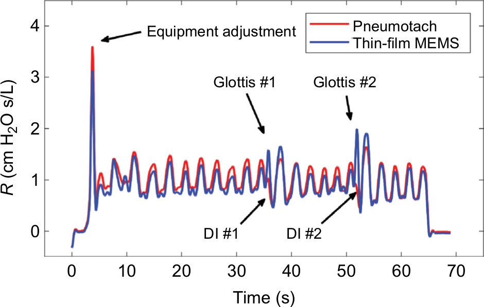 | Figure 5 Comparison of the airway resistance (R) during Trial 3 for the pneumotach and thin-film sensor connected in series. Notes: Simultaneous airway resistances for both the probes during a controlled trial with normal inhalations and two deep breaths. Glottis #1 and #2 refer to glottic closures observed during DI#1 and #2. The sensitivity for the thin-film MEMS probe is significantly larger during the DIs due to higher frequency response during these short-term events. Abbreviations: DI, deep inhalation; MEMS, micro-electro-mechanical system. |
 | Figure 6 Cross correlation of airway resistance (R) between the pneumotach and the thin-film MEMS sensor during Trial 3. Notes: (A) Total comparison of data including glottic closures. During glottic closure, the thin-film sensor shows higher resistances compared to the pneumotach, and, therefore, loop trajectories appear above the diagonal (blue loops). The coefficient of determination (R2) was 0.961, and the number of observations was 7,393. (B) Segments corresponding to glottic closures (loops) in Trial 3 are removed. The number of observations was 6,973 and R2 was 0.986. Abbreviation: MEMS, micro-electro-mechanical system. |
Frequency response comparison
There is a considerable interest in extending the range of FOT to higher frequencies.15,22–26 In the range of ~40–250 Hz, anti-resonances in the lung are prominent, and changes in the location have been correlated with spirometry. Frey et al27 have demonstrated the efficacy of the respiratory impedance at high frequencies in infants. A higher frequency response for the airflow sensor is advantageous for higher oscillatory studies. In an early study by Finucane et al,7 both screen and capillary tube pneumotachs were studied for steady state and periodic flows. Renzi et al28 have reported that pneumotachs have a frequency response up to ~20 Hz, which can be extended to 100 Hz using digital compensation.
We have measured frequency responses of the pneumotach used in this study and several thin-film probes with different geometries by sweeping the frequency delivered by the speaker from 2 to 250 Hz over a time of 30 seconds. Using STFT techniques, where the time is subdivided into shorter segments of equal length followed by a digital Fourier transform, the absolute intensity vs time for the pneumotach and a thin-film MEMS probe demonstrates dynamic testing (Figure 7). An ideal sensor should show a sharp wall of constant height along the diagonal. The Hans Rudolph Series 4700 pneumotach used in this study was observed in our setup to peak at ~45 Hz, followed by a rapid drop-off. In contrast, the thin-film MEMS probe (lower) shows a nearly constant response up to ~200 Hz. We have observed that the frequency response for thin-film MEMS sensors is very dependent on probe and sensor geometry. These observations suggest that thin-film MEMS technology offers a new platform for probing FOT frequency response over a broader frequency range that can include measurement of pulmonary anti-resonance conditions. The thin-film probe may also show promise in capturing low frequency lung sounds29 in the range of 0–200 Hz, as well as serving as an airflow sensor in spirometry and FOT.
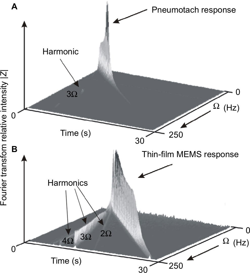 | Figure 7 Short-time Fourier transform spectra of the two types of probes used in this study. Notes: The sound frequency from the sub-woofer speaker is ramped from 2 to 250 Hz in 30 seconds. An ideal response is a steep narrow wall along the diagonal as time increases. (A) The Hans Rudolph pneumotach showed a limited response up to ~45 Hz. (B) The thin-film MEMS probe similar to the one used in this study showed an almost constant response up to ~200 Hz and then fell off. Both the graphs (A) and (B) display frequency harmonics. The pneumotach (A) shows a small 3 Ω harmonic indicating a small deviation from sinusoidal behavior. The thin-film MEMS sensor (B) shows harmonics at 2, 3 (most prominent), 4, and 5 Ω due to the larger degree of non-sinusoidal sensor output. Abbreviation: MEMS, micro-electro-mechanical system. |
Discussion
In this analysis, no artificial correction factors were employed for calibration purposes. The two data streams from the pneumotach and thin-film MEMS sensors were normalized by their root mean squares values, followed by identical RLS analysis. We used a separate independent calibration for the pneumotach to set the calibration for both MEMS and pneumotach flow sensors.
We have demonstrated quantitatively that thin-film MEMS sensors can be used to track airway resistance and provide data that “fit like a glove” with pneumotach data. Highly flexible thin-film and fiber technologies offer promise for a new method to measure low levels of oscillatory flow with increased sensitivity and functionality. For portable equipment used in the field, flexible and compliant electronics30,31 may be a simple solution to one of the problems facing the pneumotach, namely clogging of the screen or tubes with dirt or mucus, which seriously compromises accuracy and reproducibility.32 The pneumotach is also typically equipped with a heater to keep condensation from forming on the pneumotach screen. An additional benefit of the thin-film MEMS structure is that heat is generated during operation through resistive heating (~0.1 W), preventing moisture condensation during subject testing.
These data leave several unanswered questions, particularly regarding the limits for increasing the sensitivity of both the sensors and thereby avoiding the necessity of heavy large speakers and an accompanying power source. Thin-film technology is amenable to modifications in size, substrate flexibility, and the addition of sophisticated electronics. We note that the filtered raw data for Trial 3 show that the thin-film MEMS oscillatory response increased abruptly at 38 and 52 seconds, in contrast to the pneumotach, suggesting that the thin flow sensors may be more responsive to rapid changes in air flow. Our frequency sweep studies also indicate a wider frequency response for the MEMS sensor compared to a pneumotach.
Conclusion
These data support the hypothesis that thin-film MEMS sensors based on polyimide substrates can be successfully used to replace the pneumotach in the FOT instrument. Other transducers33 useful for pulmonary airflow include hot-wire anemometers, turbines, and ultrasonic time-of-flight. Ultrasonic time-of-flight has been used to obtain preliminary oscillatory data suitable for FOT analyses.34,35 To our knowledge, this study represents the first description using a thin-film MEMS device for FOT. We are continuing to develop home-based FOT devices that will be useful for patients with labile obstructive lung disease who are at high risk of hospitalization and emergency room visits. Our vision is to develop portable multi-parameter monitoring devices that can send data to a central server where they are stored against the patients’ medical records. A portable, easy-to-use, home-based FOT instrument will reduce costly hospital and emergency visits for obstructive pulmonary constriction.36
Acknowledgments
Sensors were fabricated at the Princeton Institute for the Science and Technology of Materials, an interdisciplinary research center at Princeton University. Calibration work was performed at Boston University’s Respiratory and Physiological Systems Identification Laboratory. Feather Sensors, LLC (Millville, NJ, USA) is the manufacturer of the MEMS sensor system that was used in this study. We thank Larry Ericksen and Patrick Lichter for their insights and comments on the preparation of this manuscript.
This work was supported by the National Science Foundation under SBIR Grant 1248714.
Author contributions
CEF, REC, SLM, BDG, and KRL participated in the conception and design of research. XKX, BPH, KRL, SLM, and CEF performed experiments, and XKX prepared sensors and probes. All authors contributed to data analysis, critically revising the paper, and agree to be accountable for this work.
Disclosure
CEF and REC are the owners of Feather Sensors, LLC, and XKX and SLM were employees of Feather Sensors, LLC at the time of this work. BPH was a graduate student of KRL (Boston University) during this work. The authors report no other conflicts of interest in this work.
References
Dubois AB, Brody AW, Lewis DH, Burgess BF. Oscillation mechanics of lungs and chest in man. J Appl Physiol. 1956;8(6):587–594. | ||
Bates JH. Lung Mechanics: An Inverse Modeling Approach. Cambridge: Cambridge University Press; 2009. | ||
Lutchen KR, Suki B. Understanding pulmonary mechanics using the forced oscillations technique. In: Khoo MCK, editor. Bioengineering Approaches to Pulmonary Physiology and Medicine. Boston, MA: Springer; 1996:227–253. | ||
Strömberg NO, Grönkvist MJ. Improved accuracy and extended flow range for a Fleisch pneumotachograph. Med Biol Eng Comput. 1999;37(4):456–460. | ||
Kreit JW, Sciurba FC. The accuracy of pneumotachograph measurements during mechanical ventilation. Am J Respir Crit Care Med. 1996;154(4 Pt 1):913–917. | ||
Gregory GA, Kitterman JA. Pneumotachograph for use with infants during spontaneous or assisted ventilation. J Appl Physiol. 1971;31(5):766–767. | ||
Finucane KE, Egan BA, Dawson SV. Linearity and frequency response of pneumotachographs. J Appl Physiol. 1972;32(1):121–126. | ||
Forbes C, Coifman R, Monfre S. Assessment of a low cost thin film bidirectional airflow probe for pulmonary applications. Biochem Physiol. 2012;1:1–6. | ||
Suo Z. Mechanics of stretchable electronics and soft machines. MRS Bull. 2012;37(03):218–225. | ||
Larsen GL, Morgan W, Heldt GP, et al. Impulse oscillometry versus spirometry in a long-term study of controller therapy for pediatric asthma. J Allergy Clin Immunol. 2009;123(4):861–867.e1. | ||
Navajas D, Farré R. Forced oscillation assessment of respiratory mechanics in ventilated patients. Crit Care. 2001;5(1):3–18. | ||
Regelmann WE, Schechter MS, Wagener JS, et al. Pulmonary exacerbations in cystic fibrosis: young children with characteristic signs and symptoms. Pediatr Pulmonol. 2013;48(7):649–657. | ||
Jensen A, Atileh H, Suki B, Ingenito EP, Lutchen KR. Selected contribution: airway caliber in healthy and asthmatic subjects: effects of bronchial challenge and deep inspirations. J Appl Physiol. 2001;91(1):506–515. | ||
Avanzolini G, Barbini P, Cappello A, Cevenini G, Chiari L. A new approach for tracking respiratory mechanical parameters in real-time. Ann Biomed Eng. 1997;25(1):154–163. | ||
Bates JH, Lauzon AM, Dechman GS, Maksym GN, Schuessler TF. Temporal dynamics of pulmonary response to intravenous histamine in dogs: effects of dose and lung volume. J Appl Physiol. 1994;76(2):616–626. | ||
Avanzolini G, Barbini P, Cappello A, Cevenini G. Real-time tracking of parameters of lung mechanics: emphasis on algorithm tuning. J Biomed Eng. 1990;12(6):489–495. | ||
Lutchen KR, Jensen A, Atileh H, et al. Airway constriction pattern is a central component of asthma severity: the role of deep inspirations. Am J Respir Crit Care Med. 2001;164(2):207–215. | ||
Dellacà RL, Santus P, Aliverti A, et al. Detection of expiratory flow limitation in COPD using the forced oscillation technique. Eur Respir J. 2004;23(2):232–240. | ||
Peslin R, Ying Y, Gallina C, Duvivier C. Within-breath variations of forced oscillation resistance in healthy subjects. Eur Respir J. 1992;5(1):86–92. | ||
Bhatawadekar SA, Leary D, Chen Y, et al. A study of artifacts and their removal during forced oscillation of the respiratory system. Ann Biomed Eng. 2013;41(5):990–1002. | ||
Leary D, Bhatawadekar SA, Parraga G, Maksym GN. Modeling stochastic and spatial heterogeneity in a human airway tree to determine variation in respiratory system resistance. J Appl Physiol. 2012;112(1):167–175. | ||
Chalker RB, Celli BR, Habib RH, Jackson AC. Respiratory input impedance from 4 to 256 Hz in normals and chronic airflow obstruction: comparisons and correlations with spirometry. Am Rev Respir Dis. 1992;146(3):570–576. | ||
Dorkin HL, Lutchen KR, Jackson AC. Human respiratory input impedance from 4 to 200 Hz: physiological and modeling considerations. J Appl Physiol. 1988;64(2):823–831. | ||
Farré R, Peslin R, Oostveen E, Suki B, Duvivier C, Navajas D. Human respiratory impedance from 8 to 256 Hz corrected for upper airway shunt. J Appl Physiol. 1989;67(5):1973–1981. | ||
Habib RH, Suki B, Bates JH, Jackson AC. Serial distribution of airway mechanical properties in dogs: effects of histamine. J Appl Physiol. 1994;77(2):554–566. | ||
Jackson AC, Giurdanella CA, Dorkin HL. Density dependence of respiratory system impedances between 5 and 320 Hz in humans. J Appl Physiol. 1989;67(6):2323–2330. | ||
Frey U, Silverman M, Kraemer R, Jackson AC. High-frequency respiratory impedance measured by forced-oscillation technique in infants. Am J Respir Crit Care Med. 1998;158(2):363–370. | ||
Renzi PE, Giurdanella CA, Jackson AC. Improved frequency response of pneumotachometers by digital compensation. J Appl Physiol. 1990;68(1):382–386. | ||
Gavriely N, Nissan M, Cugell DW, Rubin AH. Respiratory health screening using pulmonary function tests and lung sound analysis. Eur Respir J. 1994;7(1):35–42. | ||
Tsay C, Lacour SP, Wagner S, Li T, Suo Z. How stretchable can we make thin metal films? Poster presented at: Materials Research Society Symposium Proceedings; March 28–April 1; 2005 San Francisco, CA. | ||
Lacour SP, Chan D, Wagner S, Li T, Suo Z. Mechanisms of reversible stretchability of thin metal films on elastomeric substrates. Appl Phys Lett. 2006;88(20):204103. | ||
Schibler A, Hall GL, Businger F, et al. Measurement of lung volume and ventilation distribution with an ultrasonic flow meter in healthy infants. Eur Respir J. 2002;20(4):912–918. | ||
Gravenstein JS, Jaffe MB, Gravenstein N, Paulus DA. Capnography. Cambridge: Cambridge University Press; 2011. | ||
Araujo GA, Junior RT, Freire R, et al. Ultrasonic anemometer for the measurement of respiratory flow in the forced oscillation technique. Poster presented at: IEEE International Workshop on Medical Measurement and Applications, 2007 (MEMEA’07); May 4–5, 2007; Warsaw, Poland. | ||
Cao J, Sabharwal A. Portable forced oscillation device for point-of-care pulmonary function testing. Conf Proc IEEE Eng Med Biol Soc. 2016;2016:2282–2286. | ||
Coifman RE. Dynamic approach to asthma. J Asthma. 1983;20(1):45–52. |
 © 2018 The Author(s). This work is published and licensed by Dove Medical Press Limited. The
full terms of this license are available at https://www.dovepress.com/terms
and incorporate the Creative Commons Attribution
- Non Commercial (unported, 3.0) License.
By accessing the work you hereby accept the Terms. Non-commercial uses of the work are permitted
without any further permission from Dove Medical Press Limited, provided the work is properly
attributed. For permission for commercial use of this work, please see paragraphs 4.2 and 5 of our Terms.
© 2018 The Author(s). This work is published and licensed by Dove Medical Press Limited. The
full terms of this license are available at https://www.dovepress.com/terms
and incorporate the Creative Commons Attribution
- Non Commercial (unported, 3.0) License.
By accessing the work you hereby accept the Terms. Non-commercial uses of the work are permitted
without any further permission from Dove Medical Press Limited, provided the work is properly
attributed. For permission for commercial use of this work, please see paragraphs 4.2 and 5 of our Terms.