Back to Journals » International Journal of Nanomedicine » Volume 11
A nano-sandwich construct built with graphene nanosheets and carbon nanotubes enhances mechanical properties of hydroxyapatite–polyetheretherketone scaffolds
Authors Feng P, Peng S ![]() , Wu P, Gao C, Huang W, Deng Y, Xiao T, Shuai C
, Wu P, Gao C, Huang W, Deng Y, Xiao T, Shuai C
Received 20 April 2016
Accepted for publication 19 June 2016
Published 28 July 2016 Volume 2016:11 Pages 3487—3500
DOI https://doi.org/10.2147/IJN.S110920
Checked for plagiarism Yes
Review by Single anonymous peer review
Peer reviewer comments 2
Editor who approved publication: Professor Lei Yang
Pei Feng,1,* Shuping Peng,2,3,* Ping Wu,4 Chengde Gao,1 Wei Huang,1 Youwen Deng,5 Tao Xiao,5 Cijun Shuai1
1State Key Laboratory of High Performance Complex Manufacturing, 2The Key Laboratory of Carcinogenesis and Cancer Invasion of the Chinese Ministry of Education, 3The Key Laboratory of Carcinogenesis of the Chinese Ministry of Health and Cancer Research Institute, Xiangya Hospital, Central South University, Changsha, 4College of Chemistry, Xiangtan University, Xiangtan, 5Department of Orthopedics, The Second Xiangya Hospital, Central South University, Changsha, People’s Republic of China
*These authors contributed equally to this work
Abstract: A nano-sandwich construct was built by combining two-dimensional graphene nanosheets (GNSs) and one-dimensional carbon nanotubes (CNTs) to improve the mechanical properties of hydroxyapatite–polyetheretherketone (HAP–PEEK) scaffolds for bone tissue engineering. In this nano-sandwich construct, the long tubular CNTs penetrated the interlayers of graphene and prevented their aggregation, increasing the effective contact area between the construct and matrix. The combination of GNSs and CNTs in a weight ratio of 2:8 facilitated the dispersion of each other and provided a synergetic effect in enhancing the mechanical properties. The compressive strength and modulus of the scaffolds were increased by 63.58% and 56.54% at this time compared with those of HAP–PEEK scaffolds, respectively. The carbon-based fillers, pulling out and bridging, were also clearly observed in the matrix. Moreover, the dangling of CNTs and their entangling with GNSs further reinforced the mechanical properties. Furthermore, apatite layer formed on the scaffold surface after immersing in simulated body fluid, and the cells attached and spread well on the surface of the scaffolds and displayed good viability, proliferation, and differentiation. These evidence indicate that the HAP–PEEK scaffolds enhanced by GNSs and CNTs are a promising alternative for bone tissue engineering.
Keywords: scaffold, mechanical properties, apatite-forming ability, cell culture, tissue engineering
Introduction
Graphene nanosheets (GNSs) are a kind of two-dimensional carbon nanomaterials with sp2 hybridized carbon atoms arranged in a honeycomb pattern. They can act as excellent reinforcement for polymer due to their high modulus (~1 TPa) and strength (~130 GPa) as well as large aspect ratio (600–10,000).1,2 For instance, the tensile strength and Young’s modulus of polystyrene increased by 70% and 57%, respectively, by the addition of 0.9 wt% GNSs.3 In addition, GNSs, especially graphene oxide nanosheets, have good cytocompatibility, which allow cell adhesion and proliferation.4–6 Therefore, GNSs are highly expected to be used in reinforcing bone scaffolds. However, GNSs are prone to aggregate and stack due to the strong π–π interactions and large van der Waals forces, which lead to poor dispersion in matrix, and then this largely hampers the reinforcement efficiency.7–9
Carbon nanotubes (CNTs), one-dimensional carbon nanomaterials, possess the unique long and tubular structures of nanosized diameter and large length/diameter ratio.10–12 A sandwich construct can be built by introducing the one-dimensional CNTs into two-dimensional GNSs. CNTs prevent GNS aggregation through the long and tubular structure penetrating the interlayers of graphene. In this construct, the one-dimensional CNTs can support the two-dimensional GNSs, and the polymer chains can entangle with the sandwich construct, increasing the effective contact area between the nano-sandwich construct and the matrix to improve the mechanical properties of polymer scaffolds.13–17 Polyetheretherketone (PEEK) is a kind of polymer material that has been used as bone scaffold material because of good biocompatibility and mechanical compatibility, as well as excellent processing properties.18–20 However, PEEK is bioinert and shows limited ability to bind to natural bone tissue.21,22 Hydroxyapatite (HAP) has good biocompatibility and biodegradability and can form a strong bone bonding with bone tissue.23–25 It is predicted that the addition of HAP to PEEK can improve the biological properties of scaffolds for bone tissue engineering application. However, the introduction of HAP into PEEK matrix will decrease the mechanical strength of scaffolds, especially in highly porous structure.
In recent years, hybridization of CNTs and GNSs to enhance the mechanical properties of polymer has attracted the attention of researchers.26–30 Li et al26 added CNTs and GNSs into epoxy and found that the addition of 0.5 wt% of CNTs–GNSs hybrid led to an increase of 40% in tensile modulus and 36% in tensile strength compared with those of neat epoxy. Yang et al incorporated CNTs and GNSs into poly(arylene ether nitrile) with a weight ratio of 5:3 and found that the tensile strength and modulus were increased by 16.9% and 15%, respectively.27 However, most studies related to the synergetic enhancement with CNTs and GNSs were focused on a single type of polymer material.
In this study, a nano-sandwich construct was built to improve the mechanical properties of HAP–PEEK scaffolds by combining two-dimensional GNSs and one-dimensional CNTs. In addition, the scaffold with interconnected porous structure was successfully fabricated using selective laser sintering (SLS). The effects of GNSs and CNTs on the decentralized state, microstructure, phase composition, and mechanical properties were investigated. Reinforcing mechanisms of the nano-sandwich construct in matrix were analyzed. In addition, in vitro apatite-forming ability, cytocompatibility, proliferation, and differentiation of the scaffold were studied by simulated body fluid (SBF) immersion and cell culture tests.
Experimental materials
PEEK powder with an average particle size of ~20 μm was purchased from Dongguan Guanhui Plastic Materials Co., Ltd. (Guangdong, People’s Republic of China). Nano-HAP powder with a width of 20 nm and a length of 150 nm was supplied by Nanjing Emperor Nano Material Co., Ltd. (Jiangsu, People’s Republic of China). GNSs with a thickness of 0.8–1.2 nm and a diameter of 1–5 μm were obtained from Nanjing JCNANO Technology Co., Ltd. (Jiangsu, People’s Republic of China). Multi-walled CNTs with an average diameter of 30 nm and a length of 10–30 μm were produced by the chemical vapor deposition method and supplied by Nanjing XFNANO Materials Tech Co., Ltd. (Jiangsu, People’s Republic of China). The morphologies of the raw materials are shown in Figure 1A. The GNSs were a characteristic sheet-like structure, while CNTs were tube-like structure.
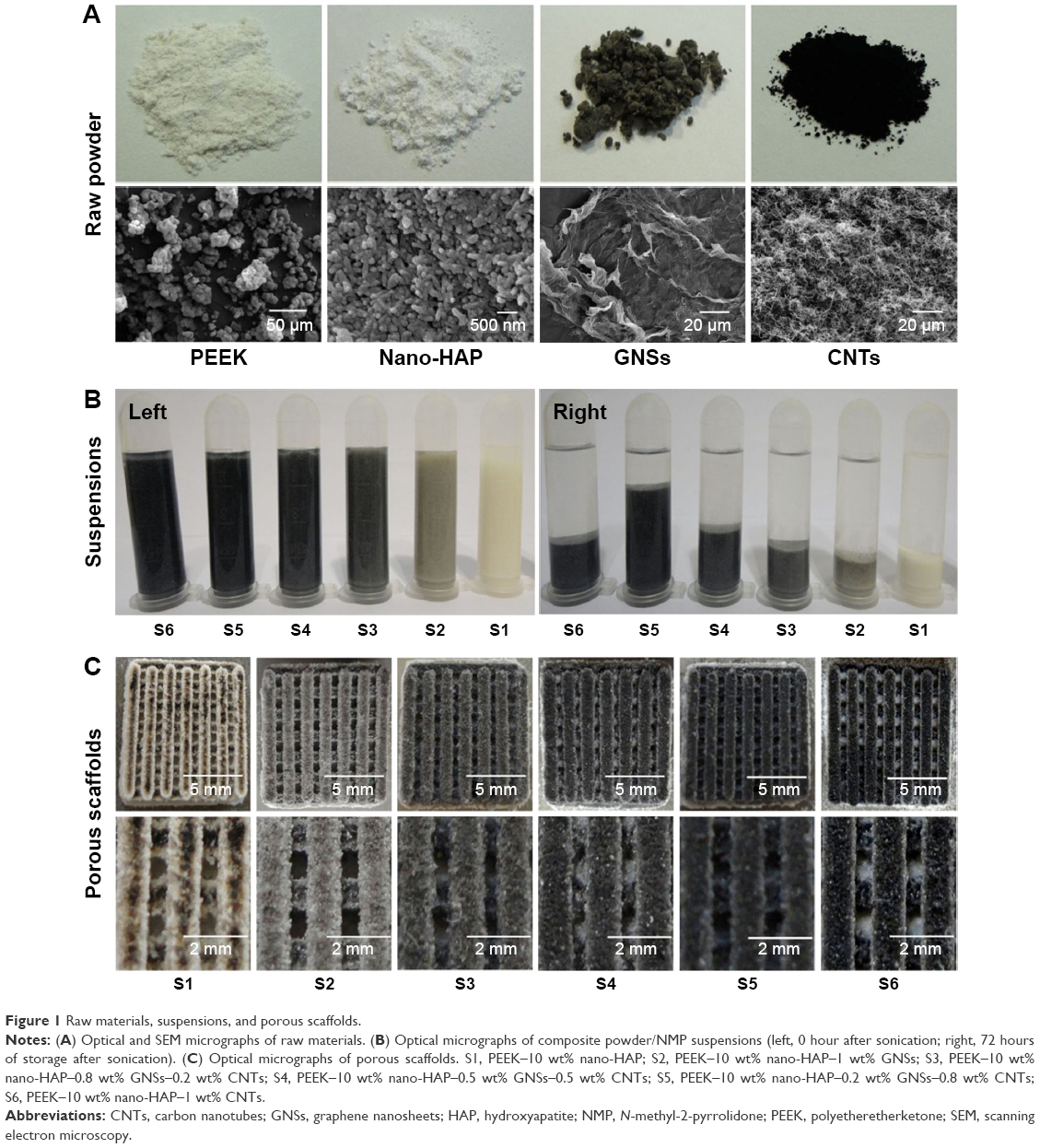 | Figure 1 Raw materials, suspensions, and porous scaffolds. |
N-Methyl-2-pyrrolidone (NMP) was supplied by Tianjin Kermel Chemical Reagent Co., Ltd. (Tianjin, People’s Republic of China). All the chemicals used for preparing SBF and phosphate-buffered saline (PBS) were purchased from Beijing Chemical Reagent Company (Beijing, People’s Republic of China). The MG-63 human osteoblast-like cells and human bone marrow mesenchymal stem cells (hBMSCs) were purchased from American Type Culture Collection (Manassas, VA, USA). Fetal bovine serum and Dulbecco’s Modified Eagle’s Medium (DMEM) were purchased from Cellgro Mediatech, Inc. (Manassas, VA, USA). With the exception of specialized reagents, cell-culture-related reagents were obtained from Thermo Fisher Scientific (Waltham, MA, USA). 4,6-Diamidino-2-phenylindole, propidium iodide, dimethyl sulfoxide, and calcein acetoxymethylester (calcein-AM) were supplied by Sigma-Aldrich Co. (St Louis, MO, USA).
Scaffolds
Composite powder containing nano-HAP and GNSs/CNTs was prepared as follows: PEEK powder (90 wt%) and nano-HAP powder (10 wt%) were added to a beaker containing NMP. The solution was then sonicated for 30 minutes using an ultrasonic cleaning device (SK3300H; Shanghai Kudos Ultrasonic Instrument Co., Ltd, Shanghai, People’s Republic of China) and subsequently stirred for 30 minutes with a magnetic stirrer (JB-5; Jintan Ronghua Instrument Manufacture Co., Ltd, Jintan, People’s Republic of China). The GNSs/CNTs (w/w, 10:0, 8:2, 5:5, 2:8, and 0:10) solution was prepared according to the abovementioned process. Then, the GNSs/CNTs solution was added to the PEEK–HAP solution, and the total GNSs/CNTs content was maintained at 1 wt%. The solution was then sonicated and stirred for another 30 minutes. The dispersibility of the composite powder in NMP after sonication and stirring is shown in Figure 1B. It was observed that all the composite powder could be dispersed well in NMP after sonication without storage (Figure 1B, left). The suspensions had much different morphologies after 72 hours of storage at room temperature (Figure 1B, right). The PEEK–HAP composite powder, PEEK–HAP–GNSs composite powder, and PEEK–HAP–CNTs composite powder were easily sedimented at the bottom of the NMP solution, while the PEEK–HAP–GNSs–CNTs composite powder in the NMP solution exhibited better colloidal stability, especially when the weight ratio of GNSs to CNTs was 2:8. All the suspensions were filtered after dispersion and dried in an electrothermal blowing dry box (101-00S; Guangzhou Dayang Electronic Machinery Equipment Co., Ltd, Guangzhou, People’s Republic of China) at 80°C for 12 hours.
SLS was applied to fabricate the composite scaffolds, because it provided an efficient method to construct the customized geometric shape and interconnected porous structure of scaffolds. In the SLS process, the computer aided design model of scaffold was first exported to stereolithography format and then transferred to the SLS system. A thin layer of powder was deposited on the powder bed, and the laser beam selectively irradiated the powder bed according to the slice data. The fabrication was performed under laser power of 2.5 W and a spot diameter of 1 mm. The scanning line interval, scanning speed, and layer thickness were 0.8 mm, 150 mm/min, and 0.1–0.2 mm, respectively. After one layer was scanned, the powder bed was lowered by thickness of one layer and a new powder layer was fed on the top. The process was repeated, and the scaffold was built layer by layer. Six composite scaffolds with different contents of PEEK, HAP, GNSs, and CNTs were investigated (Figure 1C), namely, S1 (PEEK–10 wt% HAP), S2 (PEEK–10 wt% HAP–1 wt% GNSs), S3 (PEEK–10 wt% HAP–0.8 wt% GNSs–0.2 wt% CNTs), S4 (PEEK–10 wt% HAP–0.5 wt% GNSs–0.5 wt% CNTs), S5 (PEEK–10 wt% HAP–0.2 wt% GNSs–0.8 wt% CNTs), S6 (PEEK–10 wt% HAP–1 wt% CNTs) (Table 1). Their dimension was 10 mm (length) ×10 mm (width) ×5 mm (thickness). All the scaffolds were highly porous with even distribution and good interconnectivity. Pore size and strut size were ~0.5 mm and 1 mm, respectively.
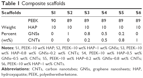 | Table 1 Composite scaffolds |
Characterization
The morphologies of the raw materials and composite scaffolds were characterized by scanning electron microscopy (SEM, FEI Quanta-200; FEI Co., Hillsboro, OR, USA). The chemical composition was analyzed by X-ray diffraction (XRD, D8 Advance; Bruker Optik GmbH, Ettlingen, Germany), Raman spectroscopy (LabRAM HR800; HORIBA Jobin Yvon, Orsay, France), and energy dispersive spectroscopy (EDS, Neptune XM4; EDAX Inc., USA). The XRD patterns were scanned in the 2θ range of 10°–40°, and the Raman spectra were recorded in the range of 1,000–2,000 cm−1.
Compression tests of the composite scaffolds were performed with a universal testing machine (WD-D1; Shanghai Zhuoji Instruments Co., Ltd, Shanghai, People’s Republic of China). The specimens were 10×10×5 mm and compressed between two steel plates, and the crosshead displacement speed was 0.5 mm/min. The compressive modulus was obtained from the slopes in the initial elastic region of the stress–strain curve. Six specimens were used for the test, and the average value was calculated.
Biomineralization
Assessment of the apatite-forming ability was carried out in SBF, which had an ionic composition similar to that of human blood plasma.31 The specimens with dimensions of 10 mm (length) ×10 mm (width) ×5 mm (thickness) were soaked in SBF at 37°C for 7 days at a concentration of 0.1 cm2/mL in polyethylene bottles. The specimens were removed from the SBF after soaking and rinsed three times using deionized water, and then dried at 37°C for 24 hours. The surface morphology and chemical composition of the scaffolds were analyzed by SEM and EDS, respectively.
Cell culture
MG-63 cells and hBMSCs were used to investigate the cell response to the scaffolds. They were cultured in DMEM containing 10% fetal bovine serum and 1% penicillin/streptomycin and maintained in a 12-well plate at 37°C in a 5% CO2 humidified atmosphere. The scaffold specimens in the size of 10×10×5 mm were sterilized in 70% ethanol for 10 minutes and then immersed in culture medium for 12 hours prior to cell seeding. A seeding density of 4×10⁵ cells/scaffold was used for attachment and proliferation. The cells were allowed to adhere to the scaffold for 2 hours before gently adding 2 mL of additional medium, followed by incubation for 1 day, 3 days, 5 days, and 7 days. To assess the attachment of MG-63 cells, the cell/scaffold constructs were removed from the wells after the predetermined time points of incubation, rinsed three times with PBS, and immediately fixed in 2.5% glutaraldehyde at pH 7.4 overnight. Afterward, the specimens were rinsed with PBS, dehydrated through a graded ethanol series, and air dried overnight. The specimens were sputtered with gold, and the morphological characteristics were examined using SEM.
To prepare specimens for fluorescent photographs, the cell/scaffold constructs were rinsed in PBS after cell culture, fixed by 4% paraformaldehyde, and then washed three times to remove excess paraformaldehyde. The live cells on the constructs were exposed to 15 μg/mL calcein-AM, 4.5 μg/mL propidium iodide, and 0.5 μg/mL 4,6-diamidino-2-phenylindole for 30 minutes. The stained specimens were observed under a fluorescence microscope (Olympus Corporation, Tokyo, Japan) equipped with a digital camera (Olympus America Inc., Melville, NY, USA). The live cells were stained green, dead cells were stained red, and the cell nucleus was stained blue.
The 3-(4,5-dimethylthiazol-2-yl)-2,5-diphenyltetrazolium bromide (MTT) assay was used to quantitatively evaluate the proliferation of hBMSCs on control and the scaffolds after 1, 3, 5, and 7 days of incubation. Briefly, 150 μL of MTT solution (5 mg/mL in PBS) was added to each scaffold, and all the specimens were incubated at 37°C for 4 hours to form formazan. The upper solvent was removed, and 150 μL of dimethyl sulfoxide was added to dissolve the formazan crystals. The optical density at a wavelength of 570 nm was measured using a spectrophotometer. The differentiation of hBMSCs was assessed by alkaline phosphatase (ALP) activity, which was conducted using p-nitrophenyl phosphate assay after 3 days and 7 days of incubation. The scaffold specimens were rinsed gently with PBS and incubated in Tris buffer containing 1% Triton X-100 solution for 10 minutes. Then, lysate was added to a 12-well plate containing 100 μL of p-nitrophenyl phosphate solution. The specimens were air dried, and the stained images were captured on a microscope.
Statistical analysis
All the data presented are mean and standard deviation for the experiments (n=6). Statistical analyses were carried out using SPSS (IBM Corporation, Armonk, NY, USA). In all analyses, a P-value <0.05 was used to indicate statistical significance.
Results and discussion
The XRD patterns of the raw powder and composite scaffolds are shown in Figure 2A. The patterns of the raw PEEK, HAP, GNSs, and CNTs powders were similar to those in other reports.32–35 In the composite scaffolds, there were only two phases including the PEEK phase and HAP phase. No typical diffraction peaks of GNSs and CNTs were detected in the composite scaffolds, which might be due to the low amount of GNSs and CNTs and the low diffraction intensity peak. The Raman spectra of GNSs and CNTs powder and S2, S4, and S6 scaffolds are shown in Figure 2B. Raman peaks were observed at 1,351 cm−1 and 1,640 cm−1 for GNSs and 1,340 cm−1 and 1,580 cm−1 for CNTs.36–38 In the composite scaffolds S2, S4, and S6, the Raman peaks of GNSs and CNTs were observed, which confirmed that the GNSs and CNTs existed after laser fabrication.
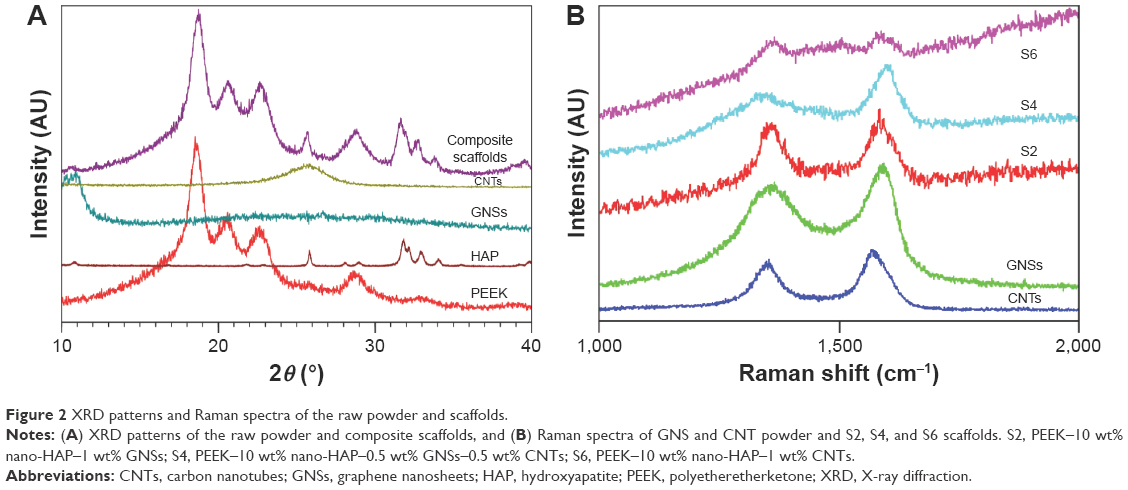 | Figure 2 XRD patterns and Raman spectra of the raw powder and scaffolds. |
The surface and fracture surface morphologies of S1, S2, S5, and S6 are shown in Figure 3. The surface and fracture surface of S1 scaffold were quite smooth and homogeneous (Figure 3A and B). For the S2 scaffold, GNSs were non-uniformly dispersed and stacked in the matrix (Figure 3C and D). The stacked graphene sheets formed steric obstacles and restricted polymer to flow, resulting in the formation of holes and defects. For the S6 scaffold, CNTs were difficult to be uniformly dispersed and aggregated in the matrix (Figure 3E and F). The stacking of GNSs and the agglomeration of CNTs reduced the reinforcing effects on the mechanical properties.39,40 It seemed that both GNSs and CNTs were homogeneously dispersed in the S5 scaffold and almost no agglomeration of GNSs and CNTs was observed (Figure 3G and H) compared with the S2 and S6 scaffolds. This was attributed to the GNSs and CNTs promoting the dispersion of each other. Moreover, a nano-sandwich construct was built by the long tubular CNTs penetrating the interlayers of the GNSs, which was expected to enhance the mechanical properties. In this construct, one end of CNTs supported the GNSs and inhibited their stacking, and the other end of CNTs embedded in the matrix.
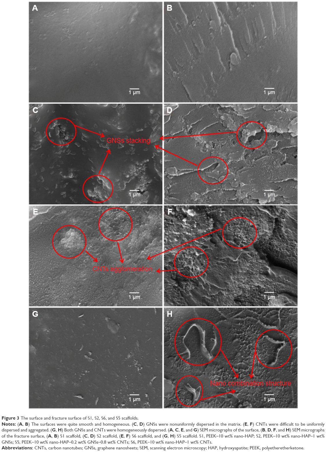 | Figure 3 The surface and fracture surface of S1, S2, S6, and S5 scaffolds. |
The scheme of GNSs and CNTs dispersed in the PEEK matrix is depicted in Figure 4. GNSs were easily stacked in the matrix, due to the strong π–π interactions and large van der Waals forces (Figure 4A). As a result, the PEEK chain could not penetrate into the interlayers of GNSs and the contact surface area with the matrix was decreased. CNTs did not disperse well in the PEEK matrix since they agglomerate easily due to the large aspect ratio and van der Waals forces (Figure 4E). As the GNS content decreased and CNT content increased in the composite scaffolds, the dispersion state of GNSs was significantly improved (Figure 4B–D). The improvement could be attributed to the long tubular CNTs penetrating the interlayers of GNSs during the sonication and stirring steps and constructed a sandwich structure to inhibit the stacking of GNSs, especially for the S5 scaffold (Figure 4D). This suggested that the one-dimensional CNTs could support the two-dimensional GNSs and inhibit the stacking of GNSs.41 The PEEK chain could penetrate easily into the interlayers of GNSs and become entangled with the sandwich structure, which significantly enhanced the contact area between the structure and matrix.42
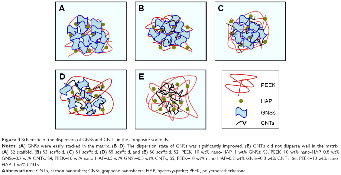 | Figure 4 Schematic of the dispersion of GNSs and CNTs in the composite scaffolds. |
The mechanical properties of the composite scaffolds with different carbon-based filler were evaluated using compressive test. The compressive strength and modulus of the S1, S2, S3, S4, S5, and S6 scaffolds are shown in Figure 5. They were ~48.08 MPa and 3.06 GPa for the S1 scaffold, respectively. The compressive strength and modulus increased with the addition of GNSs and CNTs. For example, the compressive strength and modulus were 53.23 MPa and 3.31 GPa, respectively, for S2 scaffold and 52.12 MPa and 3.15 GPa, respectively, for S6 scaffold. The limited improvement of the strength and modulus in the PEEK–HAP–GNSs and PEEK–HAP–CNTs scaffolds might be attributed to the stacking of GNSs and the agglomeration of CNTs. The composite scaffolds with GNS/CNT hybrids acquired a significant increase in the mechanical properties compared to the composite scaffolds with GNSs or CNTs alone. The S5 scaffold with the combination of GNSs and CNTs in a weight ratio of 2:8 had a compressive strength of 78.65 MPa and a compressive modulus of 4.79 GPa. The improvement was due to the synergetic effect between GNSs and CNTs. The mechanical properties of the carbon-based filler-enhanced scaffolds were significantly different as compared with PEEK–HAP scaffolds without carbon-based filler (P<0.01).
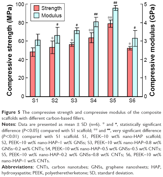 | Figure 5 The compressive strength and compressive modulus of the composite scaffolds with different carbon-based fillers. |
Adequate mechanical support is one of the important requirements for successful application as bone scaffolds. It is believed that the mechanical properties of scaffold should match those of the surrounding connective bone tissue to support the attachment and proliferation of cells. In general, human trabecular bone and cortical bone have compressive strength ranging from 0.1 MPa to 16 MPa and 130 MPa to 180 MPa and modulus ranging from 0.05 GPa to 0.5 GPa and 7 GPa to 30 GPa, respectively.43–45 The PEEK–HAP scaffolds in this study had compressive strength of 48.08–78.65 MPa and modulus of 3.06–4.79 GPa. Both of these values were significantly higher than those of trabecular bone and close to those of cortical bone.
To understand the enhancement mechanisms of carbon-based filler in the nanocomposite scaffolds, the fracture surfaces were examined by SEM, as shown in Figure 6. The fracture surface morphologies were different with different carbon fillers and contents. GNSs pull out and bridging were detected on the fracture surface (Figure 6A and B), and CNTs pull out and bridging were also observed (Figure 6C and D). Pulling out and bridging of carbon-based fillers would absorb more fracture energy through transferring the stress from the PEEK matrix to the reinforcements. Dangling CNTs with the other end fully embedded in the PEEK matrix were observed (Figure 6E), which indicated that CNTs formed a strong interfacial interaction with matrix. It had been reported that excellent interfacial interaction between the reinforcements and matrix played a major role in the effective stress transfer.46,47 The long tubular CNTs penetrated the GNSs and formed the sandwich construct (Figure 6F), which could inhibit the aggregation of CNTs and the stacking of graphene layers, thus improving the stress transfer between the reinforcements and matrix. The similar enhancing mechanisms have been reported by Wang et al48 and Agrawal et al.49
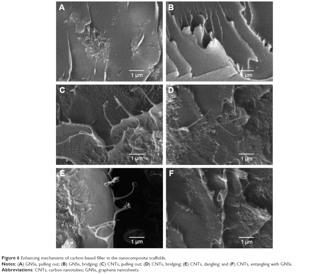 | Figure 6 Enhancing mechanisms of carbon-based filler in the nanocomposite scaffolds. |
A common character of scaffolds for bone tissue engineering application is their ability to bond to living bone through the formation of apatite layer on their surface. Surface morphologies and chemical compositions of the S1, S2, S3, S4, S5, and S6 scaffolds after soaking in SBF for 7 days were characterized by SEM and EDS, respectively, as shown in Figure 7. It could be seen that many clustered apatite islands formed on all the composite scaffolds (Figure 7A1–F1) and the morphologies were similar among different scaffolds (Figure 7A2–F2). The clustered apatite islands were constituted by hundreds of small needle-like aggregates (Figure 7A3–F3). Ca and P elements were detected in addition to C, O, and Pt elements on the apatite islands as could be observed in the EDS spectrum (Figure 7A4–F4). The results indicated that all the scaffolds had the ability to form apatite layer on their surface in SBF, which might be due to the addition of HAP to the PEEK matrix. Previous studies had shown that HAP could facilitate the formation of apatite layers between the implant material and living bone tissue.50,51
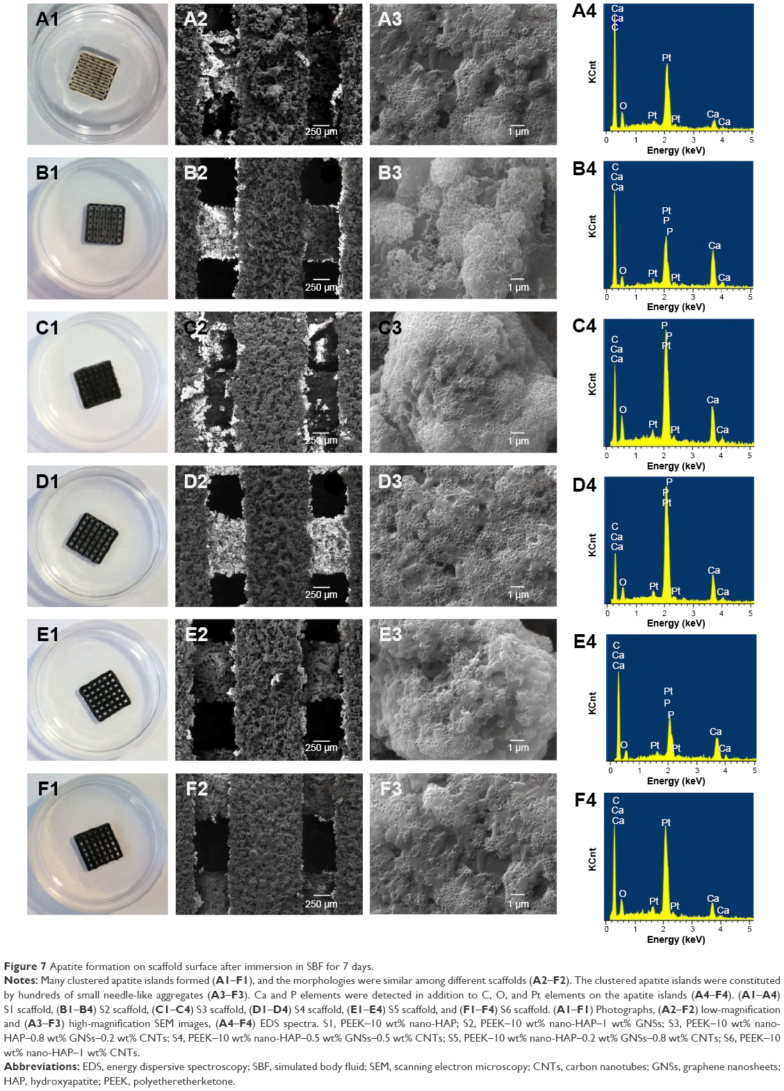 | Figure 7 Apatite formation on scaffold surface after immersion in SBF for 7 days. |
As we know, cytocompatibility is an important prerequisite of scaffolds intended for bone tissue engineering application. The S5 scaffold was selected to evaluate the cytocompatibility because of its better mechanical properties and good apatite-forming ability. The attachment and viability of MG-63 cells on the scaffold surface after 1 day, 3 days, 5 days, and 7 days of culture are shown in Figure 8. MG-63 cells attached on the scaffold surface, and extending pseudopodia were observed after 1 day of culture. Better attachment of cells and spreading of more cells were observed with increasing time of culture. The cells were spread completely and attached tightly to form a flattened sheet on the scaffold surface after incubation for 7 days. The results suggested that MG-63 cells were able to grow and proliferate well on the scaffold. In fluorescence images, the live cells on the scaffold surface appeared as bright green dots and related cytoblast as purplish blue dots. It could be seen that the cells were uniformly distributed on the scaffold surface. The cell viability of MG-63 increased significantly along with the culture time. The fluorescence microscopy results were in good agreement with the cells attachment tests. These results indicated that the scaffold was sufficiently biocompatible with MG-63 cells, as it provided a proper surface to allow cell adhesion, growth, and spreading.
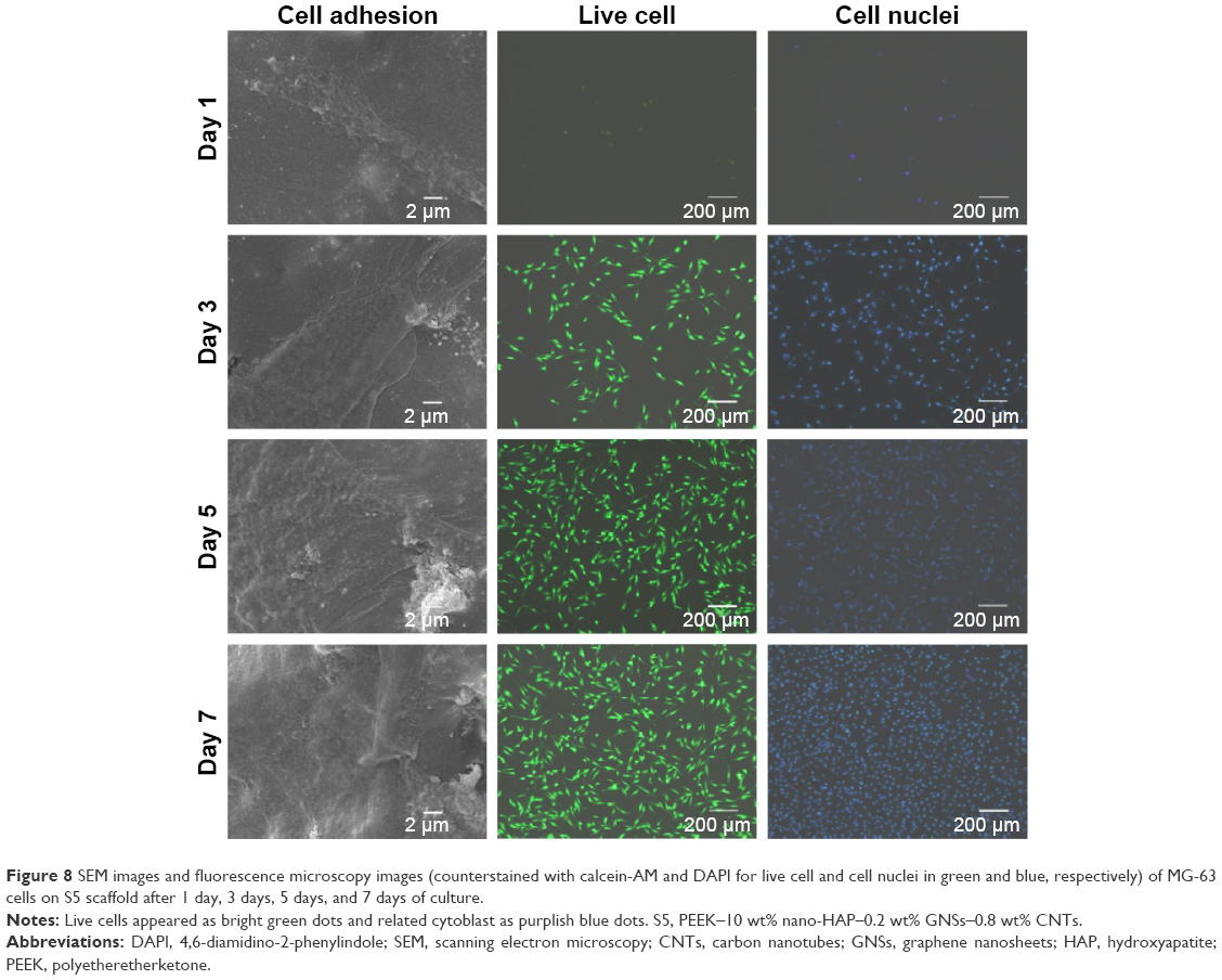 | Figure 8 SEM images and fluorescence microscopy images (counterstained with calcein-AM and DAPI for live cell and cell nuclei in green and blue, respectively) of MG-63 cells on S5 scaffold after 1 day, 3 days, 5 days, and 7 days of culture. |
Staining of live/dead cells was used to qualitatively evaluate the viability of hBMSCs on the S5 scaffold after 1 day, 3 days, 5 days, and 7 days of culture, as shown in Figure 9. Live cells and dead cells were stained green and red, respectively. Live cells had a polygonal morphology on the scaffold surface, and no dead cells were observed at 1 day (Figure 9A). The attachment area of live cells on the scaffold surface increased with increasing time of culture (Figure 9B–D). The majority of the hBMSCs were viable, and there were only a few dead cells. The results were in good agreement with the viability of MG-63 cells on the S5 scaffold. Proliferation and differentiation of the hBMSCs on the S5 scaffold were studied using MTT assay and ALP staining analysis, respectively, as shown in Figure 10. There was an increase in cell proliferation rate with increasing time of culture (Figure 10A). The cell density at 7 days was much greater than that at 1 day. The S5 scaffold had positive effect on cell proliferation with dramatically higher optical density than the control at the same culture time. The S5 scaffold had positive ALP staining after 3 days and 7 days of culture (Figure 10B–E). The ALP activity for the hBMSCs on day 7 was higher than that on day 3. It demonstrated that the S5 scaffold had good cytocompatibility for the viability, proliferation, and differentiation of hBMSCs, which might be due to the addition of HAP into PEEK matrix.52,53
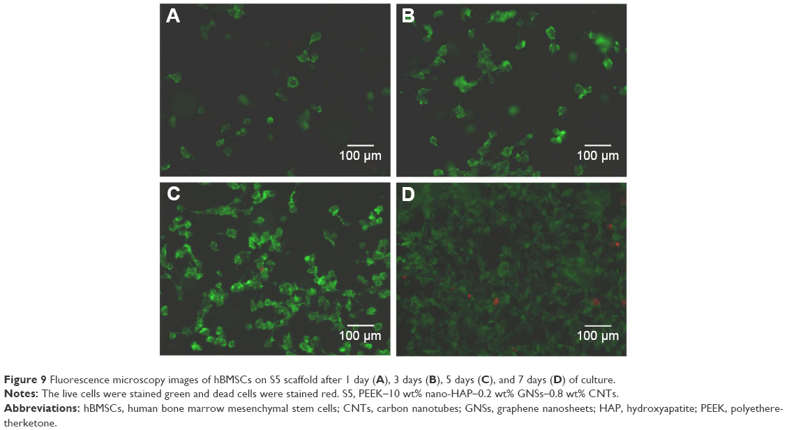 | Figure 9 Fluorescence microscopy images of hBMSCs on S5 scaffold after 1 day (A), 3 days (B), 5 days (C), and 7 days (D) of culture. |
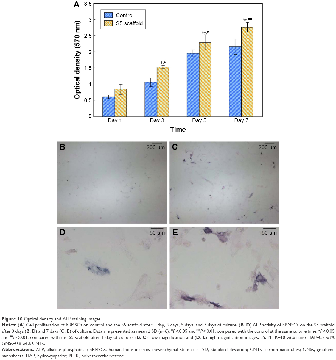 | Figure 10 Optical density and ALP staining images. |
Conclusion
In this study, two-dimensional GNSs and one-dimensional CNTs were combined to form a nano-sandwich construct through the long tubular CNTs penetrating the interlayers of graphene. The structure exhibited a synergetic effect in enhancing the mechanical properties of HAP–PEEK scaffolds fabricated via SLS. The combination of GNSs and CNTs in a weight ratio of 2:8 facilitated better dispersion in the matrix. The scaffold had a compressive strength of 78.65 MPa and a modulus of 4.79 GPa at this time. Apatite layer was deposited on the scaffold surface when soaked in SBF, indicating good apatite-forming ability. In vitro cell culture confirmed that the cells attached, spread, and proliferated well on the scaffold surface. Our results indicated that the composite scaffolds possessed excellent mechanical properties, good apatite-forming ability, and cytocompatibility and are potential alternative for bone tissue engineering.
Acknowledgments
This work was supported by the following funds: the Natural Science Foundation of China (51575537, 81572577); Overseas, Hong Kong & Macao Scholars Collaborated Researching Fund of National Natural Science Foundation of China (81428018); Hunan Provincial Natural Science Foundation of China (14JJ1006, 2016JJ1027); the Project of Innovation-driven Plan of Central South University (2015CXS008, 2016CX023); the Open-End Fund for the Valuable and Precision Instruments of Central South University; the fund of the State Key Laboratory of Solidification Processing in NWPU (SKLSP201605); the fund of the State Key Laboratory for Powder Metallurgy; and the Fundamental Research Funds for the Central Universities of Central South University.
Disclosure
The authors report no conflicts of interest in this work.
References
Sadigh MAS, Marami G. Investigating the effects of reduced graphene oxide additive on the tensile strength of adhesively bonded joints at different extension rates. Mater Des. 2016;92:36–43. | ||
Yang S, Lin W, Huang Y, et al. Synergetic effects of graphene platelets and carbon nanotubes on the mechanical and thermal properties of epoxy composites. Carbon N Y. 2011;49:793–803. | ||
Fang M, Wang K, Lu H, Yang Y, Nutt S. Covalent polymer functionalization of graphene nanosheets and mechanical properties of composites. J Mater Chem. 2009;19(38):7098–7105. | ||
Gurunathan S, Han JW, Kim JH. Green chemistry approach for the synthesis of biocompatible graphene. Int J Nanomedicine. 2013;8:2719–2732. | ||
Lee TJ, Park S, Bhang SH, et al. Graphene enhances the cardiomyogenic differentiation of human embryonic stem cells. Biochem Biophys Res Commun. 2014;452(1):174–180. | ||
Nair M, Nancy D, Krishnan AG, Anjusree GS, Vadukumpully S, Nair SV. Graphene oxide nanoflakes incorporated gelatin-hydroxyapatite scaffolds enhance osteogenic differentiation of human mesenchymal stem cells. Nanotechnology. 2015;26(16):161001. | ||
Chatterjee S, Nafezarefi F, Tai NH, Schlagenhauf L, Nüesch FA, Chu BTT. Size and synergy effects of nanofiller hybrids including graphene nanoplatelets and carbon nanotubes in mechanical properties of epoxy composites. Carbon N Y. 2012;50(15):5380–5386. | ||
Zang CG, Zhu XD, Jiao QJ. Enhanced mechanical and electrical properties of nylon-6 composite by using carbon fiber/graphene multiscale structure as additive. J Appl Polym Sci. 2015;132(19):1–10. | ||
Zhang L, Pu J, Wang L, Xue Q. Synergistic effect of hybrid carbon nanotube-graphene oxide as nanoadditive enhancing the frictional properties of ionic liquids in high vacuum. ACS Appl Mater Interfaces. 2015;7(16):8592–8600. | ||
Tjong SC. Recent progress in the development and properties of novel metal matrix nanocomposites reinforced with carbon nanotubes and graphene nanosheets. Mater Sci Eng R. 2013;74(10):281–350. | ||
Madani SY, Tan A, Dwek M, Seifalian AM. Functionalization of single-walled carbon nanotubes and their binding to cancer cells. Int J Nanomedicine. 2012;7:905–914. | ||
Shin SR, Bae H, Cha JM, et al. Carbon nanotube reinforced hybrid microgels as scaffold materials for cell encapsulation. ACS Nano. 2011;6(1):362–372. | ||
Yang SY, Chang KH, Tien HW, et al. Design and tailoring of a hierarchical graphene-carbon nanotube architecture for supercapacitors. J Mater Chem. 2011;21(7):2374–2380. | ||
Zhang J, Xu Z, Shan M, et al. Synergetic effects of oxidized carbon nanotubes and graphene oxide on fouling control and anti-fouling mechanism of polyvinylidene fluoride ultrafiltration membranes. J Membr Sci. 2013;448:81–92. | ||
Wang C, Cao M, Wang P, Ao Y. Preparation, characterization of CdS-deposited graphene-carbon nanotubes hybrid photocatalysts with enhanced photocatalytic activity. Mater Lett. 2013;108:336–339. | ||
Yang SY, Lin WN, Huang YL, et al. Synergetic effects of graphene platelets and carbon nanotubes on the mechanical and thermal properties of epoxy composites. Carbon N Y. 2011;49(3):793–803. | ||
Yue L, Pircheraghi G, Monemian SA, Manas-Zloczower I. Epoxy composites with carbon nanotubes and graphene nanoplatelets-dispersion and synergy effects. Carbon N Y. 2014;78:268–278. | ||
Edwards SL, Werkmeister JA. Mechanical evaluation and cell response of woven polyetheretherketone scaffolds. J Biomed Mater Res A. 2012;100(12):3326–3331. | ||
Kizuki T, Matsushita T, Kokubo T. Apatite-forming PEEK with TiO2 surface layer coating. J Mater Sci Mater Med. 2015;26(1):5359. | ||
Jung HD, Park HS, Kang MH, et al. Polyetheretherketone/magnesium composite selectively coated with hydroxyapatite for enhanced in vitro bio-corrosion resistance and biocompatibility. Mater Lett. 2014;116:20–22. | ||
Lee JH, Jang HL, Lee KM, et al. In vitro and in vivo evaluation of the bioactivity of hydroxyapatite-coated polyetheretherketone biocomposites created by cold spray technology. Acta Biomater. 2013;9(4):6177–6187. | ||
Zheng Y, Xiong C, Zhang S, Li X, Zhang L. Bone-like apatite coating on functionalized poly (etheretherketone) surface via tailored silanization layers technique. Mater Sci Eng C Mater Biol Appl. 2015;55:512–523. | ||
Zheng Y, Xiong C, Zhang S, Li X, Zhang L. Bone-like apatite coating on functionalized poly (etheretherketone) surface via tailored silanization layers technique. Mater Sci Eng C Mater Biol Appl. 2015;55:512–523. | ||
Nga NK, Hoai TT, Viet PH. Biomimetic scaffolds based on hydroxyapatite nanorod/poly (d, l) lactic acid with their corresponding apatite-forming capability and biocompatibility for bone-tissue engineering. Colloids Surf B Biointerfaces. 2015;128:506–514. | ||
Feng P, Niu M, Gao C, Peng S, Shuai C. A novel two-step sintering for nano-hydroxyapatite scaffolds for bone tissue engineering. Sci Rep. 2014;4:5599. | ||
Li W, Dichiara A, Bai J. Carbon nanotube-graphene nanoplatelet hybrids as high-performance multifunctional reinforcements in epoxy composites. Compos Sci Technol. 2013;74:221–227. | ||
Yang X, Zhan Y, Yang J, Zhong J, Zhao R, Liu X. Synergetic effect of cyanogen functionalized carbon nanotube and graphene on the mechanical and thermal properties of poly (arylene ether nitrile). J Polym Res. 2012;19(1):1–6. | ||
Li Y, Yang T, Yu T, Zheng L, Liao K. Synergistic effect of hybrid carbon nanotube-graphene oxide as a nanofiller in enhancing the mechanical properties of PVA composites. J Mater Chem. 2011;21(29):10844–10851. | ||
Hatui G, Bhattacharya P, Sahoo S, Dhibar S, Das CK. Combined effect of expanded graphite and multiwall carbon nanotubes on the thermo mechanical, morphological as well as electrical conductivity of in situ bulk polymerized polystyrene composites. Compos Part A Appl Sci. 2014;56:181–191. | ||
Zhang S, Yin S, Rong C, Huo P, Jiang Z, Wang G. Synergistic effects of functionalized graphene and functionalized multi-walled carbon nanotubes on the electrical and mechanical properties of poly (ether sulfone) composites. Eur Polym J. 2013;49(10):3125–3134. | ||
Kheradmandfard M, Fathi MH, Ahangarian M, Zahrani EM. In vitro bioactivity evaluation of magnesium-substituted fluorapatite nanopowders. Ceram Int. 2012;38(1):169–175. | ||
Li M, Zhang A, Yin J, Liew KY. Microwave promoted synthesis and characterization of isomeric poly (ether ether ketone)s. Polym Eng Sci. 2011;51(1):23–27. | ||
Shuai C, Feng P, Gao C, Li Z, Peng S. Processing and characterization of laser sintered hydroxyapatite scaffold for tissue engineering. Biotechnol Bioproc Eng. 2013;18:520–527. | ||
Liu Y, Luo C, Cui G, Yan S. Synthesis of manganese dioxide/iron oxide/graphene oxide magnetic nanocomposites for hexavalent chromium removal. RSC Adv. 2015;5(67):54156–54164. | ||
Hernández-Ferrer J, Laporta P, Gutiérrez F, Rubianes MD, Rivas G, Martínez MT. Multi-walled carbon nanotubes/graphene nanoribbons hybrid materials with superior electrochemical performance. Electrochem commun. 2014;39:26–29. | ||
Lalwani G, Henslee AM, Farshid B, et al. Two-dimensional nanostructure-reinforced biodegradable polymeric nanocomposites for bone tissue engineering. Biomacromolecules. 2013;14(3):900–909. | ||
Wang C, Li Y, Ding G, Xie X, Jiang M. Preparation and characterization of graphene oxide/poly (vinyl alcohol) composite nanofibers via electrospinning. J Appl Polym Sci. 2013;127(4):3026–3032. | ||
Andón FT, Kapralov AA, Yanamala N, et al. Biodegradation of single-walled carbon nanotubes by eosinophil peroxidase. Small. 2013;9(16):2721–2729. | ||
Quirino RL, Garrison TF, Kessler MR. Matrices from vegetable oils, cashew nut shell liquid, and other relevant systems for biocomposite applications. Green Chem. 2014;16(4):1700–1715. | ||
Xia H, Zhang X, Shi Z, et al. Mechanical and thermal properties of reduced graphene oxide reinforced aluminum nitride ceramic composites. Mater Sci Eng A. 2015;639:29–36. | ||
Sun Y, Tian J, Wang L, Yan H, Qiao F, Qiao X. One pot synthesis of magnetic graphene/carbon nanotube composites as magnetic dispersive solid-phase extraction adsorbent for rapid determination of oxytetracycline in sewage water. J Chromatogr A. 2015;1422:53–59. | ||
Rashad M, Pan F, Tang A, Asif M, Aamir M. Synergetic effect of graphene nanoplatelets (GNPs) and multi-walled carbon nanotube (MW-CNTs) on mechanical properties of pure magnesium. J Alloys Compd. 2014;603:111–118. | ||
Feng P, Wei P, Shuai C, Peng S. Characterization of mechanical and biological properties of 3-D scaffolds reinforced with zinc oxide for bone tissue engineering. PLoS One. 2014;9(1):e87755. | ||
Gerhardt LC, Boccaccini AR. Bioactive glass and glass-ceramic scaffolds for bone tissue engineering. Materials. 2010;3(7):3867–3910. | ||
Li LH, Kommareddy KP, Pilz C, Zhou CR, Fratzl P, Manjubala I. In vitro bioactivity of bioresorbable porous polymeric scaffolds incorporating hydroxyapatite microspheres. Acta Biomater. 2010;6(7):2525–2531. | ||
Li W, Dichiara A, Bai J. Carbon nanotube-graphene nanoplatelet hybrids as high-performance multifunctional reinforcements in epoxy composites. Compos Sci Technol. 2013;74:221–227. | ||
Liao H, Wu Y, Wu M, Zhan X, Liu H. Aligned electrospun cellulose fibers reinforced epoxy resin composite films with high visible light transmittance. Cellulose. 2012;19(1):111–119. | ||
Wang PN, Hsieh TH, Chiang CL, Shen MY. Synergetic effects of mechanical properties on graphene nanoplatelet and multiwalled carbon nanotube hybrids reinforced epoxy/carbon fiber composites. J Nanomater. 2015;2015:7. | ||
Agrawal R, Nieto A, Chen H, Mora M, Agarwal A. Nanoscale damping characteristics of boron nitride nanotubes and carbon nanotubes reinforced polymer composites. ACS Appl Mater Interfaces. 2013;5(22):12052–12057. | ||
Hassan MI, Sultana N, Hamdan S. Bioactivity assessment of poly (ε-caprolactone)/hydroxyapatite electrospun fibers for bone tissue engineering application. J Nanomater. 2014;2014:573238. | ||
Li D, Sun HF, Hu XH, Lin YL, Xu B. Facile method to prepare PLGA/hydroxyapatite composite scaffold for bone tissue engineering. Mater Sci Techol Lond. 2013;28(6):316–323. | ||
Fang B, Wan YZ, Tang TT, Gao C, Dai KR. Proliferation and osteoblastic differentiation of human bone marrow stromal cells on hydroxyapatite/bacterial cellulose nanocomposite scaffolds. Tissue Eng Part A. 2009;15(5):1091–1098. | ||
Eslaminejad MB, Bagheri F, Zandi M, et al. Comparison of proliferation and osteoblast differentiation of marrow-derived mesenchymal stem cells on nano-and micro-hydroxyapatite contained composite scaffolds. Iran J Biotechnol. 2010;8:234–242. |
 © 2016 The Author(s). This work is published and licensed by Dove Medical Press Limited. The
full terms of this license are available at https://www.dovepress.com/terms
and incorporate the Creative Commons Attribution
- Non Commercial (unported, 3.0) License.
By accessing the work you hereby accept the Terms. Non-commercial uses of the work are permitted
without any further permission from Dove Medical Press Limited, provided the work is properly
attributed. For permission for commercial use of this work, please see paragraphs 4.2 and 5 of our Terms.
© 2016 The Author(s). This work is published and licensed by Dove Medical Press Limited. The
full terms of this license are available at https://www.dovepress.com/terms
and incorporate the Creative Commons Attribution
- Non Commercial (unported, 3.0) License.
By accessing the work you hereby accept the Terms. Non-commercial uses of the work are permitted
without any further permission from Dove Medical Press Limited, provided the work is properly
attributed. For permission for commercial use of this work, please see paragraphs 4.2 and 5 of our Terms.