")
Back to Journals » International Journal of Nanomedicine » Volume 12
A magnetically responsive nanocomposite scaffold combined with Schwann cells promotes sciatic nerve regeneration upon exposure to magnetic field
Authors Liu ZY, Zhu S, Liu L, Ge J, Huang LL, Sun Z, Zeng W, Huang JH , Luo ZJ
Received 23 June 2017
Accepted for publication 17 September 2017
Published 24 October 2017 Volume 2017:12 Pages 7815—7832
DOI https://doi.org/10.2147/IJN.S144715
Checked for plagiarism Yes
Review by Single anonymous peer review
Peer reviewer comments 2
Editor who approved publication: Dr Linlin Sun
Zhongyang Liu,1,* Shu Zhu,1,* Liang Liu,2,* Jun Ge,3,4,* Liangliang Huang,1 Zhen Sun,1 Wen Zeng,5 Jinghui Huang,1 Zhuojing Luo1
1Department of Orthopedics, Xijing Hospital, Fourth Military Medical University, Xi’an, Shaanxi, 2Department of Orthopedics, No 161 Hospital of PLA, Wuhan, Hubei, 3Department of Orthopedics, No 323 Hospital of PLA, Xi’an, Shaanxi, 4Department of Anatomy, Fourth Military Medical University, Xi’an, Shaanxi, 5Department of Neurosurgery, Tangdu Hospital, Fourth Military Medical University, Xi’an, Shaanxi, People’s Republic of China
*These authors contributed equally to this work
Abstract: Peripheral nerve repair is still challenging for surgeons. Autologous nerve transplantation is the acknowledged therapy; however, its application is limited by the scarcity of available donor nerves, donor area morbidity, and neuroma formation. Biomaterials for engineering artificial nerves, particularly materials combined with supportive cells, display remarkable promising prospects. Schwann cells (SCs) are the absorbing seeding cells in peripheral nerve engineering repair; however, the attenuated biologic activity restricts their application. In this study, a magnetic nanocomposite scaffold fabricated from magnetic nanoparticles and a biodegradable chitosan–glycerophosphate polymer was made. Its structure was evaluated and characterized. The combined effects of magnetic scaffold (MG) with an applied magnetic field (MF) on the viability of SCs and peripheral nerve injury repair were investigated. The magnetic nanocomposite scaffold showed tunable magnetization and degradation rate. The MGs synergized with the applied MF to enhance the viability of SCs after transplantation. Furthermore, nerve regeneration and functional recovery were promoted by the synergism of SCs-loaded MGs and MF. Based on the current findings, the combined application of MGs and SCs with applied MF is a promising therapy for the engineering of peripheral nerve regeneration.
Keywords: peripheral nerve repair, magnetic nanoparticle, nanocomposite, magnetic field, Schwann cell, functional recovery
Introduction
The peripheral nervous system displays remarkable regenerative potential after injury.1 Although autologous nerve grafting is still considered the golden criterion and the most common therapy after peripheral nerve injury, its application is limited by the scarcity of available donor nerve, donor area morbidity, and neuroma formation.2,3 In recent decades, materials for engineering artificial nerves have become attractive treatments to repair peripheral nerve injuries,4 as they partially restore nerve regeneration by providing guidance cues for axonal regrowth. Many seeding cells and optimized nerve materials have been introduced to establish a tunable local milieu for regenerating axons at the spot of nerve deficiency and further improve nerve regeneration,5,6 thus holding great potential as a substitute for autologous nerves in nerve repair.
Schwann cells (SCs), the main gliocytes in the peripheral nerve system, are useful transplant seeding cells with positive functions in nerve repair due to their role in the organization of Büngner bands, potential to form myelin, and expression of multiple neurotrophic factors.7–10 Based on the above-mentioned considerations, the delivery of SCs to neural engineering biomaterials has recently been shown to be beneficial for nerve repair.11–15 However, attenuated biotic functions have been detected in SC cultures in vitro, which further dramatically restricts the application of SCs in peripheral nerve repair in vivo.16
In recent years, magnetic composites consisting of magnetic nanoparticles (MNPs) controlled with the applied magnetic field (MF) have been fabricated to enhance the biologic properties of cells and tissue engineering repair. A magnetic composite combined with an MF is capable of accelerating the proliferation rate of endothelial cells, facilitating the endothelial cells into capillary-like architectures,17 promoting cardiac cells to form myocardial tissue in vitro,18 stimulating human bone-derived mesenchymal stem cell proliferation,19 and improving osteogenesis in bone tissue repair in vivo.20 Moreover, an MNP-based magnetic nanocomposite hydrogel was synthesized for potential cartilage tissue engineering under MF.21 However, it is unclear whether the combination of magnetic composites and MF, especially the introduction of seeding cells, can be applied for promoting the peripheral nerve repair.
As shown in our previous study, magnetic nanocomposites composed of MNPs and chitosan–glycerophosphate combined with the applied MF upregulated the biotic functions of SCs, as well as the expression and secretion of multiple neurotrophic factors from SCs in vitro.22 However, the degradation of the magnetic scaffold (MG) is unclear, which is the essential factor required by all tissue engineering biomaterials for in vivo application.23 The variation of magnetization during the degradation time is unknown, which is a key element for the transplantation of the MG under exposure to MF in vivo. Furthermore, the efficiency of SCs combined with the magnetic nanocomposite scaffold exposed to MF on regenerating axons and promoting functional recovery after injury in vivo is still unknown.
In this study, we prepared a magnetic nanocomposite scaffold composed of MNPs and chitosan–glycerophosphate, which was loaded with SCs to form an SCs-loaded MG system. We first analyzed the structure and characterization of the MG. Then, a 15 mm long sciatic nerve gap in rats was bridged by this scaffold system. The distribution and viability of the SCs within the scaffolds upon exposure to MF were examined after surgery. Moreover, the efficiency of the SCs-loaded magnetically responsive scaffold on regenerating axons and in promoting functional neurologic recovery was further evaluated following exposure to MF.
Materials and methods
Preparation of the magnetically responsive nanocomposite scaffold
MNPs were synthesized using a previously described approach.24 Briefly, 2.728 g of KNO3 (≥99%; Sigma-Aldrich, St Louis, MO, USA) and 0.972 g of NaOH (≥98%; Sigma-Aldrich) were intermixed and then solubilized in 270 mL of deionized water in a N2 bubble bath. Then, during 4 h of N2 flow, 30 mL of a 0.01 M H2SO4 (≥98%; Sigma-Aldrich) solution including 0.616 g of FeSO4·7H2O (≥99%; Sigma-Aldrich) was mixed to the solution that had previously been prepared with constant stirring. When the precipitation was completed, an additional 20 min of N2 flow would have elapsed, and the product was heated to a higher temperature at 90°C for an additional 24 h. In the end, the product was cooled down to ambient temperature. The black products were segregated by magnetic decantation and later bathed in deionized water several times to rinse all the residuary impurities. The morphology, mean particle size, and distribution of MNPs were observed using transmission electron microscopy (TEM; TECNAI Spirit; FEI, Hillsboro, OR, USA). The crystal pattern of MNPs was confirmed using X-ray diffraction (Rigaku Miniflex, Tokyo, Japan). The magnetization of MNPs was detected using a vibrating sample magnetometer (665; Lake Shore Cryotronics, Westerville, OH, USA).
The magnetically responsive scaffold was prepared using a previously described method.22 Briefly, 200 mg of chitosan (molecular weight >310 kDa, Sigma-Aldrich) and 10 mL of a 0.1 M acetic acid solution were intermixed together to form a chitosan–acetic acid solution. The β-glycerophosphate salt solution, which was formed by intermixing 2 mL of PBS and 1,000 mg of β-glycerophosphate salt (Sigma-Aldrich), was added dropwise to the chitosan–acetic acid solution in an ice bath. The homogeneous solution obtained was transparent, with a pH of 7.03. The chitosan–glycerophosphate intermixture was later frozen at −80°C for 48 h and freeze-dried for an additional 36 h. The intermixture and previously prepared MNPs were sterilized with ethylene dioxide at 37°C. Then, 10 mL of deionized water was added to 200 mg of the chitosan–glycerophosphate freeze-dried powder to prepare the chitosan–glycerophosphate solution, and then 20 mg of MNPs was mixed into the above solution with strong intermixing in an ice bath for 4 h. Then, the intermixture was transferred to a customized module (2.0 mm in diameter, 25 mm in length) to fabricate the MG, and the weight ratio of MNPs was 10% in the magnetic nanocomposite, which was optimally prescreened in our previously study.22 The chitosan–glycerophosphate solution without MNPs was used as a nonmagnetic scaffold (non-MG).
Magnetic measurements of the magnetic scaffold
The magnetic attraction of the MG was assessed by a standard magnet. The magnetization of the MG at low field (34 Oe) was performed using a YSZ 01C/02C susceptometer (Sartorius Mechatronics, Muggiò, Italy). The high-field magnetization of the MG was calibrated using a vibrating sample magnetometer.
Morphologic characterization of the magnetic scaffold
The general appearance of the MG was observed with a stereomicroscope. The morphologic structure of the MG was determined using scanning electron microscope (Hitachi Ltd., Tokyo, Japan) at 5 kV. The scaffolds had been gold sputter-coated beforehand and observed in a partial vacuum. In addition, the morphologic characterization of the non-MG was also performed as described earlier.
Degradation test of the magnetic scaffold
Weight loss of the MG was observed by the degradation test. The sterilized scaffolds were immersed in sterilized PBS for different periods of time. At each week of the testing period after incubation with PBS, the scaffolds were lyophilized again. The weight and the magnetization of the freeze-dried scaffolds were measured and recorded.
In vivo biocompatibility of the magnetic scaffold
The prospective application of the MG for sciatic nerve regeneration suggested that this biomaterial would be sutured intimately with nerves. Therefore, the study of the biomaterial–tissue response of the MG with the sciatic nerve was performed. In detail, the non-MGs and the MGs (2.0 mm in diameter, 15 mm in length) were sterilized and disinfected for 30 min under ultraviolet ray, and then incubated in 0.9% saline solution before implantation. All animal procedures were performed under the approval and guidance of the Institutional Ethical Committee of Fourth Military Medical University. Twenty-four male adult Sprague Dawley rats weighing 220–250 g (obtained from the Laboratory Animal Center of Fourth Military Medical University) were randomly divided into two groups, that is, the non-MG group and the MG group. All rats were anesthetized with a 3.6% chloral hydrate solution (10 mL/kg, intraperitoneal). Under sterile conditions, the exposure of the left sciatic nerve of the animal was performed under an operating microscope and the scaffolds were placed on top of the sciatic nerve. The muscle layer was then stitched with 4-0 sutures and the skin was closed using 6-0 sutures. After surgery, the rats had access to food and water ad libitum. The animals were sacrificed at 1 and 12 weeks postimplantation. Tissue samples of intact implants were harvested en bloc for histologic analysis. The samples were immersed in 4% paraformaldehyde in 0.1 M PBS for 2 weeks at 4°C. Then, five longitudinal sections per specimen were prepared and subjected to hematoxylin and eosin staining to evaluate the biocompatibility of the MG. Histology images were photographed using a light microscope (AH3; Olympus Corporation, Tokyo, Japan).
MF stimulation system
The MF stimulation system consisted of an arc-shaped magnet twined with enamel-coated copper wire (1.00 mm diameter) and an MF producer to generate MFs with a proper frequency of 0–100 Hz and an intensity of 0–20 mT. The MF producer (GHY-III, patent ZL02224739.4; Fourth Military Medical University, Xi’an, China) was connected to the magnet to generate an open-circuit wave shape of MF. A Gaussmeter (Model 455 DSP; Lake Shore Cryotronics) was used to measure the accuracy of the MF output. A small 2 Ω resistor was properly placed in series connection, and the output frequency and the waveform were visualized on an oscillograph (6000 series; Agilent Technologies, Santa Clara, CA, USA). The frequency of MF was set to 50 Hz, as applied in previous experiments.25–27
SCs’ culture and preparation
SCs were isolated and purified following the previously described protocol.28 All the experiments were undertaken in conformity with the Guide for the Care and Use of Laboratory Animals (National Institutes of Health publication No 85-23, revised 1985).29 In brief, the sciatic and brachial plexus nerves of 2-day-old Sprague Dawley rats (obtained from the Experimental Animal Center of Fourth Military Medical University) were severed, and SCs were harvested and further sorted out from fibroblasts by adding a combination of rabbit complement and fibronectin-specific antibody. The purity of SCs was confirmed by double immunofluorescent staining with antibodies against Sox-10 (green, 1:250; Abcam, Cambridge, MA, USA) and S-100 (red, 1:250; Abcam). The number of Sox-10- and S-100-positive cells and 4′,6-diamidino-2-phenylindole–labeled cells was compared. SCs were incubated in DMEM/nutrient mixture F-12 (Thermo Fisher Scientific, Waltham, MA, USA) consisting of 15% fetal bovine serum (Thermo Fisher Scientific), antibiotics (100 μg/mL streptomycin and 100 UI/mL penicillin), 20 μg/mL bovine pituitary extract (Biomedical Technologies, Stoughton, MA, USA), and 2 μM/mL forskolin (Sigma-Aldrich) at 37°C in a humidified, 5% CO2 atmosphere.
Procedure for preparing the SCs-loaded magnetic scaffold
The MG fabricated previously was cut into cylinders (15 mm in length). The mixed scaffolds used in this experiment were composed of the magnetically responsive scaffold and SCs. The SCs-loaded MG system was constructed and then prepared for surgery.
Animals, surgical operations, and experimental design
All animal procedures were performed under the approval and guidance of the Institutional Ethical Committee of Fourth Military Medical University. A total of 306 male adult Sprague Dawley rats weighing 220–250 g (obtained from the Laboratory Animal Center of Fourth Military Medical University) were randomly divided into five groups as shown in Table 1. All animals were anesthetized with a 3.6% chloral hydrate solution (10 mL/kg, intraperitoneal). Under a sterile environment, the exposure of the left sciatic nerve of the animal was performed under an operating microscope. Then, a 15 mm long gap was made in the sciatic nerve. In the autograft group, the amputated sciatic nerve was reversed 180° and resutured. In the other four groups, the nerve scaffold was used to bridge the nerve gap, and then, both the proximal and distal nerve stumps were sutured with three perineural 10/0 prolene sutures. The skin was then stitched with 6-0 sutures in all groups. After operation, the rats were transferred back to cages and were fed with food and water ad libitum. The MF exposure groups were exposed to an applied MF at 2 mT for 2 h as previously performed, at the same time each day after surgery. Specifically, during the MF exposure time postoperation, the animals were fixed in a customized stable apparatus, and then the anarc-shaped magnet twined with copper wire was set properly at the MF stimulation area which was above the operative region of the bridged scaffold, making the orientation of the MF applied in the MG from proximal to distal, because the effect of the MF on the MG is largely dependent on the field direction. The rats bridged with the MG represented the MG group. The rats bridged with the MG and under MF exposure after surgery represented the MG+MF group. The rats bridged with the SCs-loaded MG represented the MG+SCs group. The rats bridged with the SCs-loaded MG and under MF after surgery represented the MG+SCs+MF group.
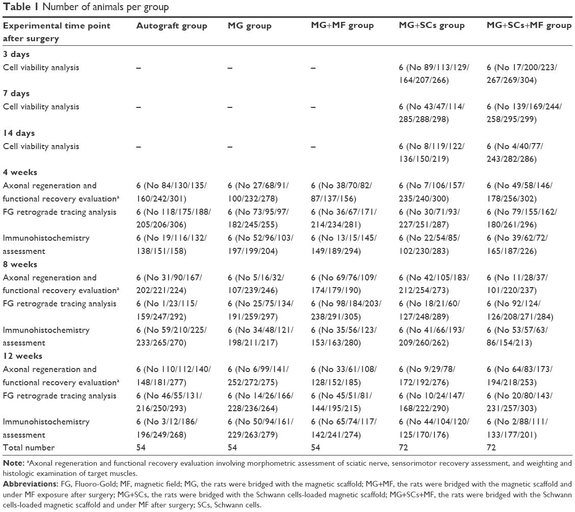 | Table 1 Number of animals per group |
Analysis of cell viability after surgery
At 3, 7, and 14 days after surgery, the rats (n=6, at every point in time of each group) were anesthetized prior to an intracardial perfusion with 0.1 M PBS followed by ice-cold 4% paraformaldehyde buffer. Then, the grafts were harvested and sectioned. Serial 25 μm thick longitudinal sections of the grafts were immediately transferred onto slides and then stained by using a Live/Dead cell staining kit (BioVision, Milpitas, CA, USA). Live cells were labeled with a green fluorescent dye Live-Dye™, for which the excitation/emission peak was at 488/518 nm, and dead cells were labeled with a red fluorescent dye propidium iodide, for which the excitation/emission peak was at 488/615 nm. The bicolor labeling was visualized, and images were captured with a fluorescence microscope (DM6000; Leica Microsystems, Wetzlar, Germany). The cell viability was confirmed by counting from six randomized fields of interest, and then expressed as the average percentage of cell survival (live cells/total cells ×100%).
Morphometric evaluation of axonal regeneration
At 4, 8, and 12 weeks postoperation, the regenerative nerves were quickly harvested and fixed in 3% glutaraldehyde for 2 h and postfixed in 1% osmium tetroxide for 2 h. After washing and dehydration, the specimens were embedded in epoxy resin media. Then, the distal portions of the regenerative nerves were cut into 1 μm of semi-thin and 50 nm of ultrathin sections transversely. The semi-thin sections were dyed by 1% toluidine blue and observed under a light microscope (AH3; Olympus Corporation). The ultrathin sections were dyed by uranyl acetate and lead citrate and were observed by TEM. Six semi-thin sections and six ultrathin sections were randomly selected at each portion of the regenerative nerve for the quantitative analysis. The total area of regenerated nerves and the total number of myelinated axons were calculated for each semi-thin section. The mean diameter of the nerve fibers and the G-ratio (the axon-to-fiber diameter ratio) were calculated and assessed for each ultrathin section.
Double immunofluorescence staining of the regenerated nerves and axons
Twelve weeks after surgery, serial longitudinal sections (thickness of 10 μm) of the middle portions of the grafted segments (~9.0 mm long) were cut on a cryostat. The sections were allowed to be incubated with the rabbit anti-S-100 monoclonal antibody (1:250; Abcam) and the mouse anti-NF200 monoclonal antibody (1:250; Abcam) at 4°C for 12 h. Next, the goat anti-rabbit IgG TRITC (1:250; Abcam) and the goat anti-mouse IgG FITC (1:250; Abcam) secondary antibodies were used to probe the primary antibodies for 1 h at 37°C. For the observation of the double immunofluorescence staining, six slides were randomly selected from each group, and each section was rinsed, mounted on glycerin-coated slides, and cover slipped. The sections were analyzed under a fluorescence microscope (DM6000; Leica).
Sensorimotor recovery analysis
At 4, 8, and 12 weeks postoperation, the locomotor function recovery was evaluated by the walking track test and the assessment of the sciatic functional index (SFI).30 Briefly, the rats’ hind paws were dipped in red nontoxic dye and the animals were made to walk across a 100×9×6 cm narrow wooden corridor. Six measurable footprints were then collected and photographed, and the SFIs were measured using the following equation: SFI =109.5× (ETS − NTS)NTS +13.3× (EIT − NIT)/NIT −38.3× (EPL − NPL)/NPL −8.8, where TS stands for toe spread (distance between the first and the fifth toe), IT stands for intermediary toe spread (distance between the second and the fourth toe), and PL stands for print length (distance between the heel and the top of the third toe). NTS, NIT, and NPL stand for the TS, IT, and PL measured from the nonsurgical foot, respectively. ETS, EIT, and EPL stand for the TS, IT, and PL measured from the surgical foot, respectively. The value of SFI that oscillated around 0 indicated normal nerve function or total nerve recovery, whereas the SFI score of ~−100 represented total dysfunction.
After SFI analysis, the sensory nociceptive function recovery of the injured hindlimb was performed using the plantar test. Briefly, the mice were placed on a transparent Plexiglas box and radiant heat was used to stimulate the left hind paw. The latency time in response to a hind paw lick or shake/jump was recorded and used as a nociception index. The testing was performed only once per time point in order to prevent sensitization. The thermal stimulus was stopped to prevent heat damage if the animals were nonresponsive for 30 s.
Retrograde Fluoro-Gold (FG) labeling
At 4, 8, and 12 weeks postoperation, FG retrograde tracing was undertaken and the back-labeled cells were calculated. Briefly, the area of sciatic nerve was exposed, and the nerve 5 mm distal to the distal end of the scaffold was crushed with a pair of forceps three times for 15 s with a 15 s interval to injure the regenerated axons, and then, intraneural injection of 5.0 μL 4% FG (Biotium, Hayward, CA, USA) was administered into the nerve trunk at the spot described earlier. Finally, the incision was sutured. The animals were kept routinely in cages for 1 week. After 1 week, 4% (w/v) paraformaldehyde in 0.1 M PBS was intracardially perfused into the rats under anesthesia. The L4–6 level of lumbar spinal cord and the corresponding dorsal root ganglia (DRG) were harvested and then sectioned within a cryostat. Serial 16 μm thick longitudinal sections of the DRG and 25 μm thick transverse sections of the spinal cord were mounted on glass slides and observed and captured using a fluorescence microscope (DM6000; Leica). Both the amount of FG-positive motoneurons from the spinal cord and sensory neurons from the DRG were calculated.
Weighing target muscles and histologic analysis
Twelve weeks after surgery, the operational and contralateral side gastrocnemius muscles were harvested and weighted, respectively. Muscle weights were normalized to the contralateral side to account for individual differences between animals. Then, the muscles were immersed in 4% paraformaldehyde in 0.1 M PBS for 2 weeks at 4°C. Then, five cross sections (thickness of 50 μm) per specimen were prepared and subjected to Masson’s trichrome staining. Next, the sections were photographed using a light microscope (AH3; Olympus) to calculate the muscles’ area. For the quantitative analysis, six randomly selected fields in each section were counted. The quantification of diameters of muscle fibers was performed using the ImageJ software (NIH, Bethesda, MD, USA).
Microvessel density (MVD) analysis
Twelve weeks postoperation, 10 μm thick cross sections of the middle portions of the regenerative nerve were prepared and the MVD was quantified using an immunofluorescence staining. Briefly, the specimens were dyed with a rabbit anti-CD34 antibody (1:250; Abcam) for 24 h at 4°C. Next, a goat anti-rabbit IgG FITC (1:250; Abcam) was added to probe the primary antibody for 2 h at 37°C. For the quantitative evaluation, six randomized fields of interest were then chosen and the microvessels were photographed under fluorescence microscope (DM6000; Leica). MVD was assessed by calculating the number of microvessels per square millimeter (vessel number/mm2).
Statistical analysis
Data were expressed as mean ± standard error of the mean or mean ± SD. The data were analyzed by SPSS 20.0 software (IBM Corporation, Armonk, NY, USA) using one-way analysis of variance. The effects of time and treatments for paired comparisons were evaluated by Bonferroni’s test. The p-values below 0.05 indicated statistical significance.
Results and discussion
In this study, we performed a series of experiments to investigate the properties of the MG and the efficacy of its combination with SCs under MF exposure on improving axonal regeneration and functional recovery after a 15 mm sciatic nerve defect was made. Figure 1A shows the experimental time scale, and Figure 1B shows that the MG combined with SCs was transplanted to bridge the 15 mm sciatic nerve gap in rats under the microscope, and a high purity of SCs (>97%) is shown in Figure 1C–F. Figure 1G illustrates the schematic diagram of the major process of this study. Based on the in vivo experiments, the combination of the SCs-loaded MGs and MF exposure promoted nerve regeneration in rats.
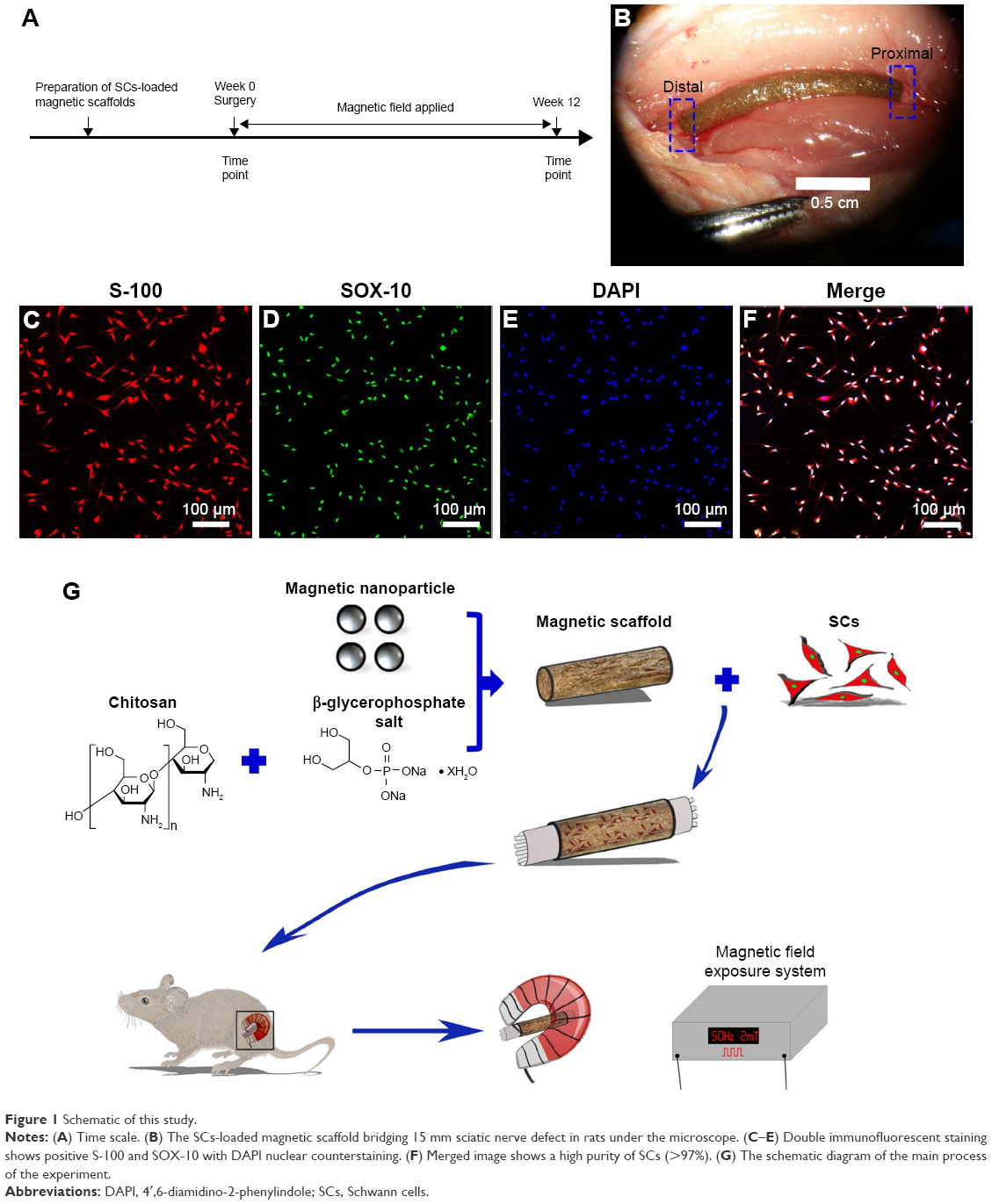 | Figure 1 Schematic of this study. |
In recent decades, MNPs have attracted increasing interest for use in biomedical applications, such as in the fields of magnetic resonance imaging, drug delivery, and cancer therapy.31–34 In this study, the MNPs were synthesized and the morphology was determined by TEM (Figure 2A). Figure 2B shows that MNPs were fairly uniform in distribution and the average particle diameter was 28.90±9.34 nm. Figure 2C reveals that the crystalline characteristic of MNPs tested by X-ray diffraction was nearly in conformity to the standard crystal structure of iron oxide.35 Meanwhile, magnetization of MNPs revealed superparamagnetism (Figure 2D).
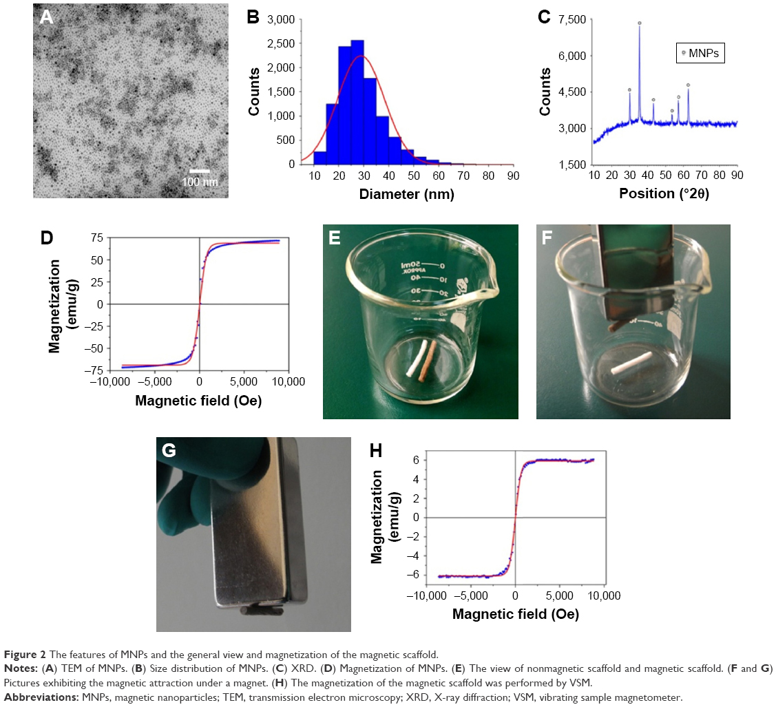 | Figure 2 The features of MNPs and the general view and magnetization of the magnetic scaffold. |
Nevertheless, MNPs alone may be unable to provide optimal properties. Integration of MNPs with other desirable components is a promising approach to fabricate nanocomposites with integrated properties for biomedical applications.21 In this study, we integrated MNPs into a chitosan–glycerophosphate mixture, which are biodegradable, nontoxic, and mucoadhesive polymers and showed good biocompatibility for neuron survival,36 to form a magnetic nanocomposite scaffold. Figure 2E shows the fabricated MG. The magnetic property was determined using a magnet (Figure 2F and G). Figure 2H shows that the MG had superparamagnetism at room temperature. In addition, the ML, which stands for the magnetization measure at low MF of 34 Oe, was 0.189 emu/g, and the MH, which stands for the magnetization at high MF of 8 kOe, was 5.722 emu/g, indicating that the MG may work as a topical MF inductor and its inherent magnetization could be inspired by MF, and the MG might be capable of being motivated continuously by the external MF because of the ingredient of MNPs.
The styles of the scaffolds used in the peripheral nerve regeneration were diverse, such as one tube, multitubes, cylinder, and so on, and the applications and effects of the above-mentioned scaffolds in promoting nerve regeneration also had their advantages and disadvantages.5,37–39 Cylinder scaffold, with its inner microchannels being made to imitate the basal nerve structures and allow the regenerating neurite outgrowth,5 was applied in our experiments. In brief, we fabricated the non-MGs and MGs using a tailored module (Figure 3A). On comparing with the white and transparent color of the non-MG (Figure 3G and H), the color of the magnetic scaffold was uniformly chocolate (Figure 3B and C), showing that the MNPs were homogeneously distributed in the material. In addition, Figure 3D and I shows that the general structure of the non-MGs and MGs was relatively porous under scanning electron microscope in the transverse view, and the non-MGs and MGs displayed a honeycomb-shaped characteristic in the cross section (Figure 3E and J) and longitudinally oriented microarrays with various lengths in the lengthwise section (Figure 3F and K). The mean diameter of the magnetic scaffold in cross section was 31.03±1.71 μm, which was ~30 μm, and this was most valid for enhancing oriented neurite outgrowth,40 since it is suitable for the alignment and guiding of the regenerating axons, as well as for the infiltration of cells and vascularization that facilitates regeneration.41,42 However, the mean diameter of the non-MGs in the cross section was 37.56±1.90 μm, which was significantly larger than the MG, and this might be that the nanosized MNPs put a cross-linking role in the integration into the chitosan-glycerophosphate mixture.43 The cross-linking function of nanosized MNPs in the MG was achieved by decreasing the biopolymer–chain distance, thus leading to the potentialities of less inner-space interconnection and more sealed microchannels. Moreover, the size of MNPs was varied, and the different diameters of MNPs might play a diverse role in the fabricated magnetic nanocomposites and then affect the interaction between the magnetic nanocomposites and cells. Further studies are needed to determine its effects.
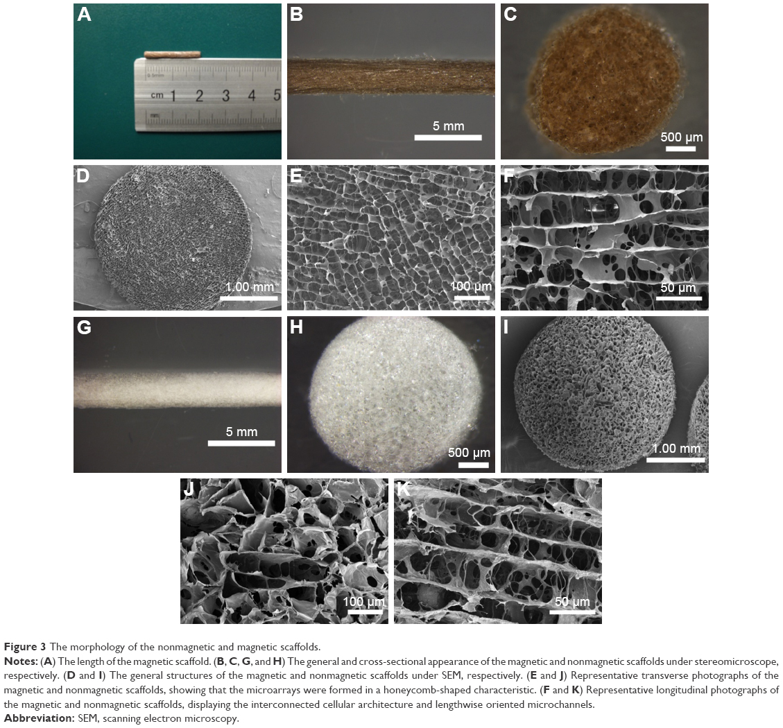 | Figure 3 The morphology of the nonmagnetic and magnetic scaffolds. |
The degradation time of materials is a crucial requirement to the application of all tissue engineering medical products, and the appropriate degradation rate allowed the nerve implant to afford a stable architecture for supporting the neonatally regenerating nerve during the first 4–6 months.23 In this study, the degradation test indicated that the MG was biodegradable, and the weight loss was 38.31%±0.67% after 12 weeks and 58.96%±0.43% after 16 weeks (Figure 4A), indicating that the MG was capable of supporting the regenerating axons. Figure 4B shows that after 12 weeks, the ML was 0.094 emu/g and the MH was 3.487 emu/g, and after 16 weeks, the ML was 0.044 emu/g and the MH was 2.512 emu/g, suggesting that the MG can be well responsive during the MF exposure period after bridging the sciatic nerve gap.
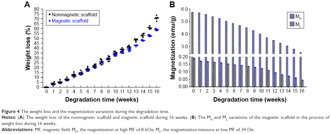 | Figure 4 The weight loss and the magnetization variations during the degradation time. |
Biodegradation and biocompatibility of neural engineering materials in vivo are two important parameters for their application in peripheral nerve repair.44 Therefore, the in vivo tissue response of the sciatic nerve and the ambient tissues to implants was determined. Figure 5A and C shows that acute inflammation and fibrous capsule formation were observed at 1 week after surgery in the area of both scaffolds. The acute inflammation of the MG was visible by the presence of the surrounding macrophages and fibrous tissue. Figure 5B and D shows that both scaffolds were degraded and the fibrous capsule thickness of the scaffolds was reduced, indicating the chronic inflammatory response of both scaffolds. Moreover, the observation of the nerve was not affected by either the non-MG or the MG at 1 and 12 weeks postoperation. These findings suggest that the magnetic scaffolds we fabricated were biodegradable and biocompatible for their further application in bridging the sciatic nerve gap in vivo. In addition, along with the degradable process of the MG, the MNPs in the scaffold were released back into the surrounding environment. Much work has shown that the size of MNPs determined their half-life in the circulation.45 For instance, MNPs with sizes larger than 200 nm became concentrated in the spleen or were ingested by phagocytes of the body, whereas MNPs smaller than 10 nm were largely removed by renal clearance. When the size of MNPs was in the range of 10–100 nm, they were able to penetrate through small capillaries46 and then to be carried through the blood circulation into the heart, lung, liver, or kidney. A previous study had shown that the MNPs (average diameter of 18 nm) integrated into MG had no indications of any pathologic changes in the heart, lung, liver, spleen, and kidney during the experiment, indicating that the recirculated MNPs had no harmful influence on the organ functions of the animal.20 In our study, the average size of MNPs was 28.90±9.34 nm, which may also be recirculated into the blood vessel during the degradable process and then be flown into the visceral organs. Further studies are needed to evaluate the distribution of recirculated MNPs in the organs, in order to shed light on the effect of the degradable ingredients on rats.
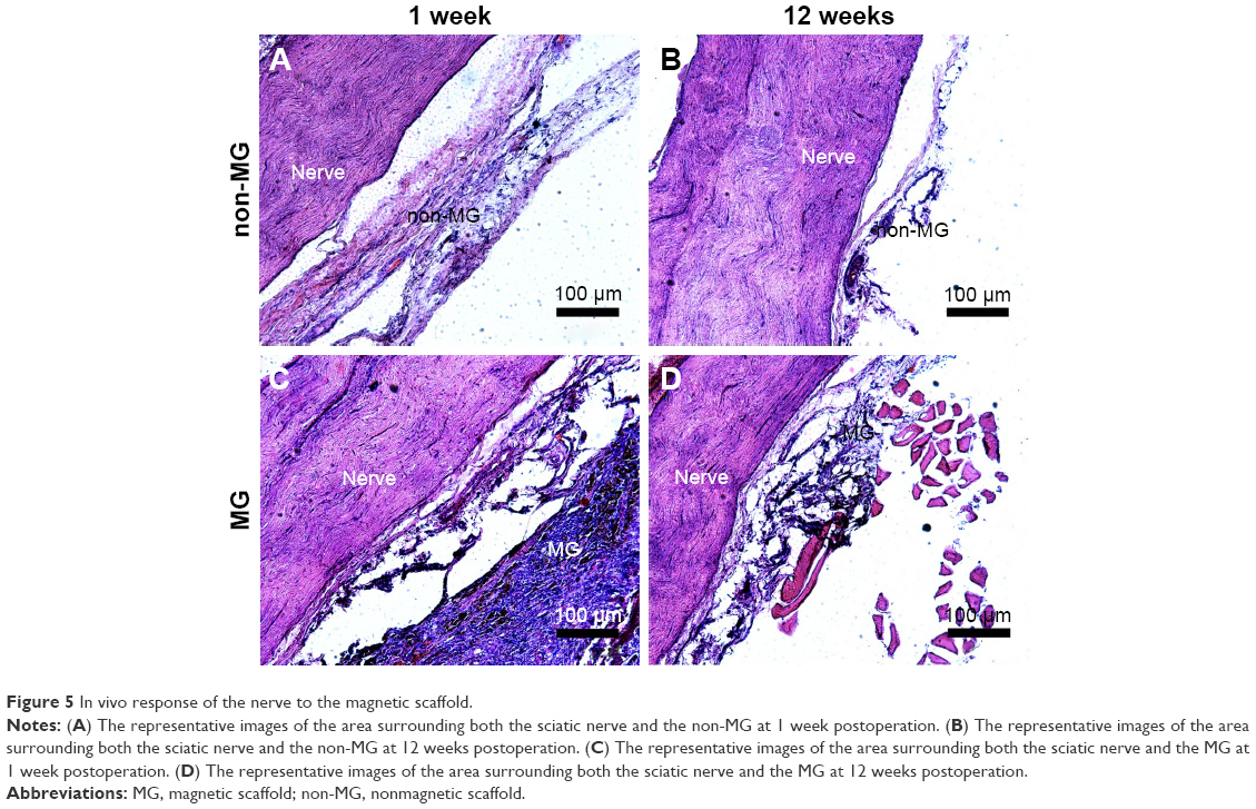 | Figure 5 In vivo response of the nerve to the magnetic scaffold. |
An adequate cell seeding efficiency and cell distribution are the two key factors to consider currently when combining nerve materials with supportive cells for nerve repair.47 Therefore, we injected the SCs into the magnetically responsive scaffold for a higher seeding efficiency and homogeneous distribution. Cell distribution within the nerve scaffolds was analyzed, and a large number of live SCs were uniformly distributed in the MG (Figure 6B, D, E, and G). The results supported the hypothesis that this MG, as a seeding cell carrier, was capable of increasing the seeding efficacy and allowing a homogenous cell distribution. In addition, cell viability within the MG was analyzed after surgery. Figure 6I shows that the number of live SCs, in comparison with the group without MF exposure, was significantly increased in the MG+SCs+MF group at 3, 7, and 14 days after implantation. A previous in vitro study showed that a magnetic gel composed of MNPs, type II collagen, polyethylene glycol, and hyaluronic acid enhances the viability of bone marrow-derived mesenchymal stem cells,48 consistent with the findings of this study. Thus, the combination of the MG and MF exposure was capable of enhancing the survival of SCs in the early stage of implantation, which could be an important favorable factor for nerve regeneration after implantation.
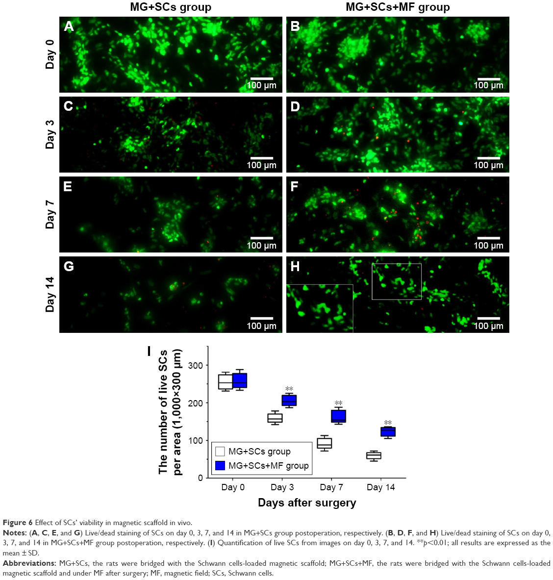 | Figure 6 Effect of SCs’ viability in magnetic scaffold in vivo. |
The formation of regenerated axons was examined using toluidine blue staining to assess the effect of the combination of SCs-loaded MG and MF on axonal regeneration. Regenerating axons were observed at the distal ends in all groups at 4, 8, and 12 weeks postoperation (Figure 7A–E). However, massive axons, including myelinated axons and unmyelinated axons, were only observed in the MG+SCs+MF group and autograft group (Figure 7F and J). In the MG+MF and MG+SCs groups, the regenerated axons showed an inferior morphologic appearance compared to the axons in the MG+SCs+MF group (Figure 7H and I), but had a better appearance than the axons in the MG group (Figure 7G). In addition, the total area of the regenerated axons (Figure 7P), the total number and the mean diameter of the myelinated axons (Figure 7Q and R) were similar between the autograft group and the MG+SCs+MF group, but were significantly increased compared to those in the other groups (p<0.05; Figure 7P–R). Moreover, the G-ratio measurement indicated that the degree of myelination was significantly improved in the MG+SCs+MF group compared to that in other groups (p<0.05; Figure 7S). In addition, no statistical significance was observed in the parameters described earlier between the autograft group and the MG+SCs+MF group (p>0.05; Figure 7S). These findings indicated that the amount of myelinated axons in nerve grafts was comparable between the autograft group and the MG+SCs+MF group at 12 weeks postoperation, which was significantly increased compared to that in other groups. Meanwhile, the myelinated axons were evenly distributed in the MG+SCs+MF group.
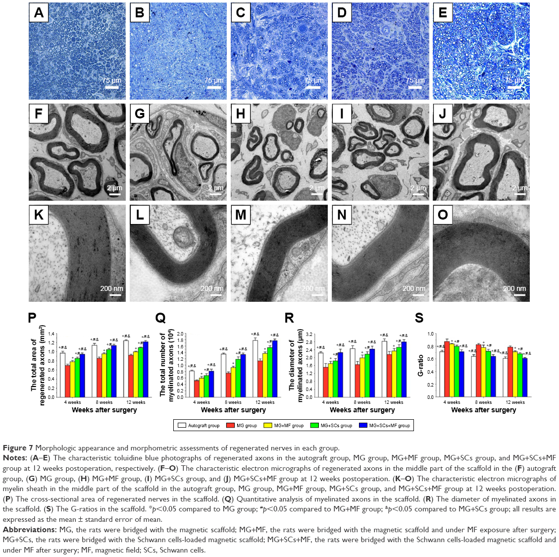 | Figure 7 Morphologic appearance and morphometric assessments of regenerated nerves in each group. |
Furthermore, double S-100/NF200 immunofluorescence staining in all sections of the regenerated nerve also revealed that the migrated SCs and regenerated axons were evenly distributed in the autograft group and MG+SCs+MF group (Figure 8A–D and Q–T) 12 weeks after the operation and revealed a better morphologic appearance than the axons in the MG, MG+MF, and MG+SCs groups (Figure 8E–P).
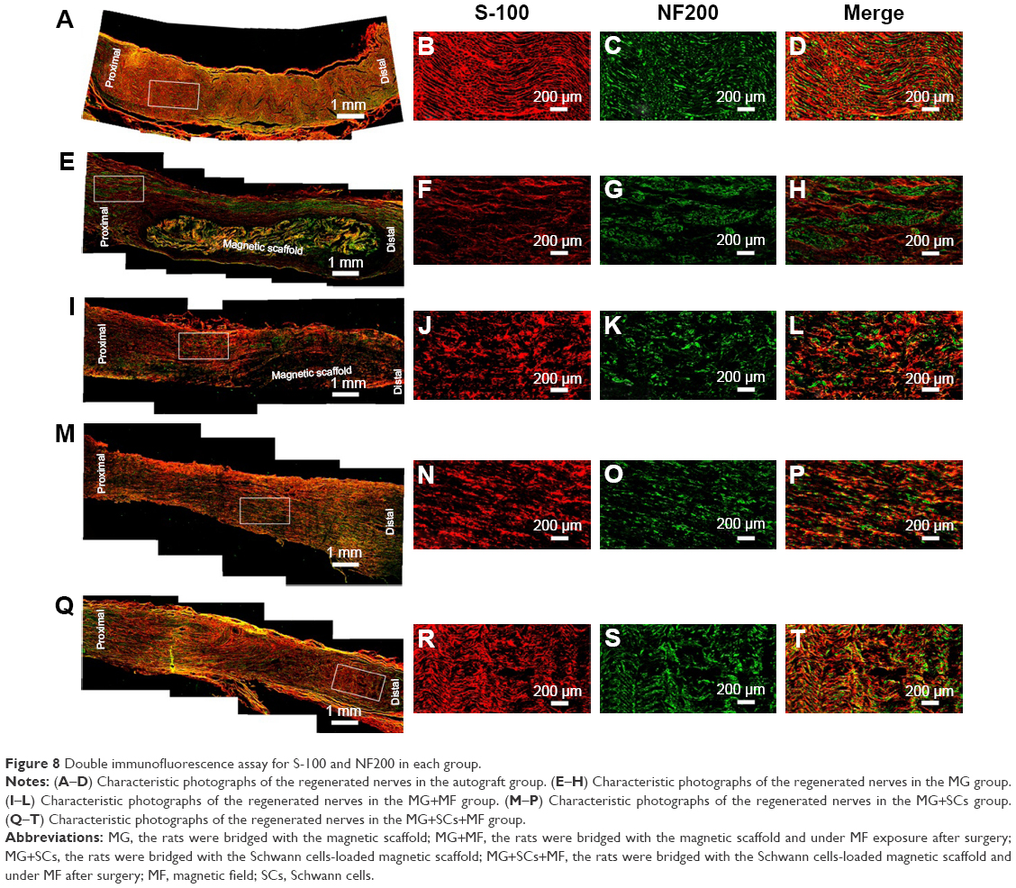 | Figure 8 Double immunofluorescence assay for S-100 and NF200 in each group. |
According to the SFI measurements shown in Figure 9A, motor function recovery was achieved in all groups at 4, 8, and 12 weeks postoperation. However, better motor functional recovery was shown by the MG+SCs+MF group, with higher SFI values than the rats in the MG, MG+MF, and MG+SCs groups (p<0.05; Figure 9B). Figure 9C indicates that sensory functional recovery was achieved in all groups at the predefined time postoperation, according to the thermal hind paw withdrawal test. The rats in the MG+SCs+MF group exhibited better sensory functional recovery, with quicker response to thermal stimulus than the rats in other groups (p<0.05; Figure 9C). Moreover, the SFI values and hind paw withdrawal latency time were similar in the autograft group and the MG+SCs+MF group at the predefined time (p>0.05; Figure 9B and C), indicating that more axons might successfully regenerate through the magnetic scaffolds from the proximal stumps to the distal stumps and reinnervate the target muscles.
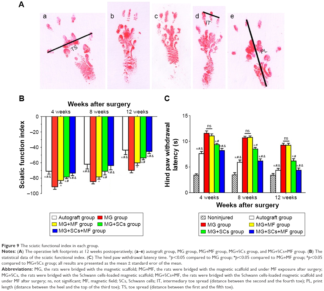 | Figure 9 The sciatic functional index in each group. |
Retrograde FG staining of spinal motoneurons and DRG sensory neurons was performed to analyze the neurons whose axons successfully regenerated through the scaffolds. The numbers of FG-positive motoneurons and sensory neurons were similar in the autograft group and the MG+SCs+MF group, but were significantly higher than the numbers observed in other groups (p<0.05; Figure 10A, E, F, and J–L). Moreover, the number of FG-positive motoneurons and sensory neurons in the MG group was significantly decreased compared to the number observed in the MG+MF and MG+SCs groups (p<0.05; Figure 10B–D, G–I, K, and L). Thus, these findings indicate that more nerve fibers from motoneurons and sensory neurons in the autograft group and MG+SCs+MF group regenerated into the distal stumps than did the nerve fibers from the remaining groups.
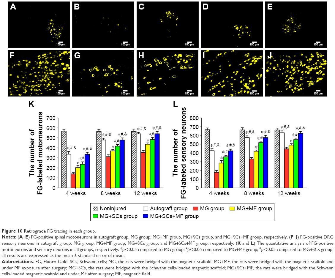 | Figure 10 Retrograde FG tracing in each group. |
Motor nerve injury results in atrophy of the denervated target muscle, which could be alleviated by reinnervation accompanied by a gradual functional recovery. Thus, weighting and morphologic assessments of the gastrocnemius muscles were performed to examine the effect of the combination of the SCs-loaded MG and MF exposure on motor function recovery. Figure 11A–E shows the representative photographs of the morphology of gastrocnemius muscles in each group at 12 weeks postoperation. Also, Masson’s trichrome staining in Figure 11F–J shows the percentage of muscle fiber area, and the average diameter of muscle fibers in the MG+MF and MG+SCs groups were significantly increased compared to the percentage in the MG group, indicating that the addition of SCs to MG or exposure to an MF partially prevented muscle atrophy. Moreover, the percentage area of muscle fiber and the average diameter of muscle fibers were similar in the autograft group and MG+SCs+MF group, but were significantly increased compared to the percentage in the MG, MG+MF, and MG+SCs groups at 12 weeks postoperation (p<0.05; Figure 11Q and R). Thus, a combination of SCs loaded in the magnetic scaffolds and MF exposure synergistically reversed muscle atrophy.
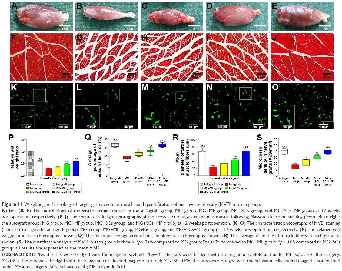 | Figure 11 Weighting and histology of target gastrocnemius muscle, and quantification of microvessel density (MVD) in each group. |
The viability and biologic functions of SCs which combined with scaffolds are relied upon both nutrient and oxygen utilization within the nerve scaffold. Vascularization is a critical factor for these purposes. Microvessels have been considered to play an efficient part in the delivery of nutrition and oxygen. Thus, an MVD experiment was performed to determine the effect of the combination of the SCs-loaded MG and MF exposure on microvessel growth within the nerve scaffold. As shown in the representative images, the MVD was comparable between the autograft group and the MG+SCs+MF group, but significantly increased compared to that in the other groups (Figure 11K–O). Further quantitative analyses showed that the MVD in the MG+SCs group was increased compared to that in the MG group (Figure 11S), indicating that SCs increased the MVD in newly formed nerve tissues and promoted vascularization. In addition, the MVD in the MG+SCs+MF group was higher than the MVD without MF (Figure 11S), suggesting that following MF exposure, the SCs-loaded MG might enhance vascularization by promoting the survival of SCs and upregulating vascularization-related genes.
These findings, combined with the increased viability of SCs in the magnetic loading system under MF exposure after implantation, together reveal that SCs-loaded MG with MF exposure have beneficial effect on the axonal regeneration and neurologic functional recovery, which might be attributable to the synergistic effect of SCs-loaded MG and MF. Further studies will be needed to explore the intrinsic mechanism of the improving axon regeneration and neurological functional recovery after bridging the sciatic nerve defect using SCs-loaded MG in response to an applied MF.
Conclusion
A magnetically responsive nanocomposite scaffold was fabricated in this study from a mixture of MNPs and chitosan–glycerophosphate polymers. The magnetic scaffolds have modest magnetization, proper degradation rate, and possess a tunable microstructure, making them suitable for cellular distribution and new axon regeneration. The combination of the magnetically responsive scaffold and SCs exposed to an MF synergistically improves nerve regeneration and functional recovery in vivo by increasing the distribution efficiency and viability of SCs. Our study reports a promising scaffold for nerve tissue engineering because the SC-loaded magnetic nanocomposite scaffold responded to an applied external MF, which may be used to remotely orient the scaffold to the nerve defect site using an externally applied MF.
Acknowledgments
This work was supported by grants from the National Natural Science Foundation of China (81672148, 81201389, and 81501047), the National Basic Research Program of China (973 Program No 2014CB542206), the National Key Research and Development Plan (2016YFC1101700), the Program for Changjiang Scholar and Innovative Research Team in University (IRT1053 and IRT13051), and A Foundation for the Author of National Excellent Doctoral Dissertation of PR China (201480). We thank the following technicians for providing excellent technical assistance: Mr Lei Zhu, Mr Xin Quan, Mr Bing Xia, Mr Yafeng Yang, Mr Teng Ma, Ms Lifeng Lan, Ms Chunmei Wang, Mr Haifeng Zhang, Ms Jing Fan, and Mr Yongqiang Li.
Disclosure
The authors report no conflicts of interest in this work.
References
Sulaiman OA, Gordon T. Effects of short- and long-term schwann cell denervation on peripheral nerve regeneration, myelination, and size. Glia. 2000;32(3):234–246. | ||
Pabari A, Yang SY, Mosahebi A, et al. Recent advances in artificial nerve conduit design: strategies for the delivery of luminal fillers. J Control Release. 2011;156(1):2–10. | ||
Jaquet JB, Luijsterburg AJ, Kalmijn S, et al. Median, ulnar, and combined median-ulnar nerve injuries: functional outcome and return to productivity. J Trauma. 2001;51(4):687–692. | ||
Jiang X, Lim SH, Mao HQ, et al. Current applications and future perspectives of artificial nerve conduits. Exp Neurol. 2010;223(1):86–101. | ||
Hu X, Huang J, Ye Z, et al. A novel scaffold with longitudinally oriented microchannels promotes peripheral nerve regeneration. Tissue Eng Part A. 2009;15(11):3297–3308. | ||
Cao J, Sun C, Zhao H, et al. The use of laminin modified linear ordered collagen scaffolds loaded with laminin-binding ciliary neurotrophic factor for sciatic nerve regeneration in rats. Biomaterials. 2011;32(16):3939–3948. | ||
Krick K, Tammia M, Martin R, et al. Signaling cue presentation and cell delivery to promote nerve regeneration. Curr Opin Biotechnol. 2011;22(5):741–746. | ||
Lago N, Casas C, Muir EM, et al. Effects of schwann cell transplants in an experimental nerve amputee model. Restor Neurol Neurosci. 2009;27(1):67–78. | ||
Rodriguez FJ, Verdu E, Ceballos D, et al. Nerve guides seeded with autologous schwann cells improve nerve regeneration. Exp Neurol. 2000;161(2):571–584. | ||
Chen ZL, Yu WM, Strickland S. Peripheral regeneration. Annu Rev Neurosci. 2007;30:209–233. | ||
Zhang YG, Sheng QS, Qi FY, et al. Schwann cell-seeded scaffold with longitudinally oriented micro-channels for reconstruction of sciatic nerve in rats. J Mater Sci Mater Med. 2013;24(7):1767–1780. | ||
Novikova LN, Pettersson J, Brohlin M, et al. Biodegradable poly-beta-hydroxybutyrate scaffold seeded with schwann cells to promote spinal cord repair. Biomaterials. 2008;29(9):1198–1206. | ||
Yeh CW, Wang LW, Wu HC, et al. Development of biomimetic micro-patterned device incorporated with neurotrophic gradient and supportive schwann cells for the applications in neural tissue engineering. Biofabrication. 2017;9(1):015024. | ||
Goulart CO, Jurgensen S, Souto A, et al. A combination of schwann-cell grafts and aerobic exercise enhances sciatic nerve regeneration. PLoS One. 2014;9(10):e110090. | ||
Luo L, Gan L, Liu Y, et al. Construction of nerve guide conduits from cellulose/soy protein composite membranes combined with schwann cells and pyrroloquinoline quinone for the repair of peripheral nerve defect. Biochem Biophys Res Commun. 2015;457(4):507–513. | ||
He J, Ding WL, Li F, et al. Panaxydol treatment enhances the biological properties of schwann cells in vitro. Chem Biol Interact. 2009;177(1):34–39. | ||
Sapir Y, Cohen S, Friedman G, et al. The promotion of in vitro vessel-like organization of endothelial cells in magnetically responsive alginate scaffolds. Biomaterials. 2012;33(16):4100–4109. | ||
Sapir Y, Polyak B, Cohen S. Cardiac tissue engineering in magnetically actuated scaffolds. Nanotechnology. 2014;25(1):014009. | ||
Zhang J, Zhao S, Zhu M, et al. 3d-printed magnetic fe3o4/mbg/pcl composite scaffolds with multifunctionality of bone regeneration, local anticancer drug delivery and hyperthermia. J Mater Chem B. 2014;2(43):7583–7595. | ||
Meng J, Xiao B, Zhang Y, et al. Super-paramagnetic responsive nanofibrous scaffolds under static magnetic field enhance osteogenesis for bone repair in vivo. Sci Rep. 2013;3:2655. | ||
Zhang N, Lock J, Sallee A, et al. Magnetic nanocomposite hydrogel for potential cartilage tissue engineering: synthesis, characterization, and cytocompatibility with bone marrow derived mesenchymal stem cells. ACS Appl Mater Interfaces. 2015;7(37):20987–20998. | ||
Liu Z, Huang L, Liu L, et al. Activation of schwann cells in vitro by magnetic nanocomposites via applied magnetic field. Int J Nanomedicine. 2015;10:43–61. | ||
Hsu SH, Chan SH, Chiang CM, et al. Peripheral nerve regeneration using a microporous polylactic acid asymmetric conduit in a rabbit long-gap sciatic nerve transection model. Biomaterials. 2011;32(15):3764–3775. | ||
Riggio C, Calatayud MP, Hoskins C, et al. Poly-l-lysine-coated magnetic nanoparticles as intracellular actuators for neural guidance. Int J Nanomed. 2012;7:3155–3166. | ||
Bai WF, Xu WC, Feng Y, et al. Fifty-hertz electromagnetic fields facilitate the induction of rat bone mesenchymal stromal cells to differentiate into functional neurons. Cytotherapy. 2013;15(8):961–970. | ||
Zhang Y, Ding J, Duan W. A study of the effects of flux density and frequency of pulsed electromagnetic field on neurite outgrowth in pc12 cells. J Biol Phys. 2006;32(1):1–9. | ||
Trillo MA, Martinez MA, Cid MA, et al. Retinoic acid inhibits the cytoproliferative response to weak 50hz magnetic fields in neuroblastoma cells. Oncol Rep. 2013;29(3):885–894. | ||
Mey J, Schrage K, Wessels I, et al. Effects of inflammatory cytokines il-1beta, il-6, and tnfalpha on the intracellular localization of retinoid receptors in schwann cells. Glia. 2007;55(2):152–164. | ||
Zhu S, Ge J, Wang Y, et al. A synthetic oxygen carrier-olfactory ensheathing cell composition system for the promotion of sciatic nerve regeneration. Biomaterials. 2014;35(5):1450–1461. | ||
Hare GM, Evans PJ, Mackinnon SE, et al. Walking track analysis: a long-term assessment of peripheral nerve recovery. Plast Reconstr Surg. 1992;89(2):251–258. | ||
Lassenberger A, Scheberl A, Stadlbauer A, et al. Individually stabilized, superparamagnetic nanoparticles with controlled shell and size leading to exceptional stealth properties and high relaxivities. ACS Appl Mater Interfaces. 2017;9(4):3343–3353. | ||
Jain TK, Richey J, Strand M, et al. Magnetic nanoparticles with dual functional properties: drug delivery and magnetic resonance imaging. Biomaterials. 2008;29(29):4012–4021. | ||
Lee JH, Jang JT, Choi JS, et al. Exchange-coupled magnetic nanoparticles for efficient heat induction. Nat Nanotechnol. 2011;6(7):418–422. | ||
Szlezak M, Nieciecka D, Joniec A, et al. Monoolein cubic phase gels and cubosomes doped with magnetic nanoparticles-hybrid materials for controlled drug release. ACS Appl Mater Interfaces. 2017;9(3):2796–2805. | ||
Cornell RM, Schwertmann U. The Iron Oxides: Structure, Properties, Reactions, Occurrences and Uses. Hoboken, NJ: John Wiley & Sons; 2003. | ||
Crompton KE, Goud JD, Bellamkonda RV, et al. Polylysine-functionalised thermoresponsive chitosan hydrogel for neural tissue engineering. Biomaterials. 2007;28(26):441–449. | ||
Harley BA, Hastings AZ, Yannas IV, et al. Fabricating tubular scaffolds with a radial pore size gradient by a spinning technique. Biomaterials. 2006;27(6):866–874. | ||
Plikk P, Malberg S, Albertsson AC. Design of resorbable porous tubular copolyester scaffolds for use in nerve regeneration. Biomacromolecules. 2009;10(5):1259–1264. | ||
Tansey KE, Seifert JL, Botterman B, et al. Peripheral nerve repair through multi-luminal biosynthetic implants. Ann Biomed Eng. 2011;39(6):1815–1828. | ||
Goldner JS, Bruder JM, Li G, et al. Neurite bridging across micropatterned grooves. Biomaterials. 2006;27(3):460. | ||
Kim YT, Haftel VK, Kumar S, et al. The role of aligned polymer fiber-based constructs in the bridging of long peripheral nerve gaps. Biomaterials. 2008;29(21):3117–3127. | ||
Bozkurt A, Deumens R, Beckmann C, et al. In vitro cell alignment obtained with a schwann cell enriched microstructured nerve guide with longitudinal guidance channels. Biomaterials. 2009;30(2):169–179. | ||
Tampieri A, Landi E, Valentini F, et al. A conceptually new type of bio-hybrid scaffold for bone regeneration. Nanotechnology. 2011;22(1):015104. | ||
Bettinger CJ, Bruggeman JP, Misra A, et al. Biocompatibility of biodegradable semiconducting melanin films for nerve tissue engineering. Biomaterials. 2009;30(17):3050–3057. | ||
Chouly C, Pouliquen D, Lucet I, et al. Development of superparamagnetic nanoparticles for mri: effect of particle size, charge and surface nature on biodistribution. J Microencapsul. 1996;13(3):245–255. | ||
Gupta AK, Wells S. Surface-modified superparamagnetic nanoparticles for drug delivery: preparation, characterization, and cytotoxicity studies. IEEE Trans Nanobioscience. 2004;3(1):66–73. | ||
Sun F, Zhou K, Mi WJ, et al. Combined use of decellularized allogeneic artery conduits with autologous transdifferentiated adipose-derived stem cells for facial nerve regeneration in rats. Biomaterials. 2011;32(32):8118–8128. | ||
Zhang N, Lock J, Sallee A, et al. Magnetic nanocomposite hydrogel for potential cartilage tissue engineering: synthesis, characterization, and cytocompatibility with bone marrow derived mesenchymal stem cells. ACS Appl Mater Interfaces. 2015;7(37):20987–20998. |
 © 2017 The Author(s). This work is published and licensed by Dove Medical Press Limited. The full terms of this license are available at https://www.dovepress.com/terms.php and incorporate the Creative Commons Attribution - Non Commercial (unported, v3.0) License.
By accessing the work you hereby accept the Terms. Non-commercial uses of the work are permitted without any further permission from Dove Medical Press Limited, provided the work is properly attributed. For permission for commercial use of this work, please see paragraphs 4.2 and 5 of our Terms.
© 2017 The Author(s). This work is published and licensed by Dove Medical Press Limited. The full terms of this license are available at https://www.dovepress.com/terms.php and incorporate the Creative Commons Attribution - Non Commercial (unported, v3.0) License.
By accessing the work you hereby accept the Terms. Non-commercial uses of the work are permitted without any further permission from Dove Medical Press Limited, provided the work is properly attributed. For permission for commercial use of this work, please see paragraphs 4.2 and 5 of our Terms.