Back to Journals » International Journal of Nanomedicine » Volume 11
Synthesis, characterization, and performance evaluation of multilayered photoanodes by introducing mesoporous carbon and TiO2 for humic acid adsorption
Authors Hosseini S, Jahangirian H ![]() , Webster T
, Webster T ![]() , Masoudi Soltani S, Aroua M
, Masoudi Soltani S, Aroua M
Received 17 September 2015
Accepted for publication 15 March 2016
Published 16 August 2016 Volume 2016:11 Pages 3969—3978
DOI https://doi.org/10.2147/IJN.S96558
Checked for plagiarism Yes
Review by Single anonymous peer review
Peer reviewer comments 3
Editor who approved publication: Professor Carlos Rinaldi
Soraya Hosseini,1 Hossein Jahangirian,2 Thomas J Webster,2 Salman Masoudi Soltani,3 Mohamed Kheireddine Aroua1
1Department of Chemical Engineering, University of Malaya, Kuala Lumpur, Malaysia; 2Department of Chemical Engineering, Northeastern University, Boston, MA, USA; 3Department of Chemical Engineering, Imperial College London, South Kensington Campus, London, UK
Abstract: Nanostructured photoanodes were prepared via a novel combination of titanium dioxide (TiO2) nanoparticles and mesoporous carbon (C). Four different photoanodes were synthesized by sol–gel spin coating onto a glassy substrate of fluorine-doped tin oxide. The photocatalytic activities of TiO2, TiO2/C/TiO2, TiO2/C/C/TiO2, and TiO2/C/TiO2/C/TiO2 photoanodes were evaluated by exposing the synthesized photoanodes to UV–visible light. The photocurrent density observed in these photoanodes confirmed that an additional layer of mesoporous carbon could successfully increase the photocurrent density. The highest photocurrent density of ~1.022 mA cm-2 at 1 V/saturated calomel electrode was achieved with TiO2/C/C/TiO2 under an illumination intensity of 100 mW cm-2 from a solar simulator. The highest value of surface roughness was measured for a TiO2/C/C/TiO2 combination owing to the presence of two continuous layers of mesoporous carbon. The resulting films had a thickness ranging from 1.605 µm to 5.165 µm after the calcination process. The presence of double-layer mesoporous carbon resulted in a 20% increase in the photocurrent density compared with the TiO2/C/TiO2 combination when only a single mesoporous carbon layer was employed. The improved performance of these photoanodes can be attributed to the enhanced porosity and increased void space due to the presence of mesoporous carbon. For the first time, it has been demonstrated here that the photoelectrochemical performance of TiO2 can be improved by integrating several layers of mesoporous carbon. Comparison of the rate of removal of humic acid by the prepared photoanodes showed that the highest performance from TiO2/C/C/TiO2 was due to the highest photocurrent density generated. Therefore, this study showed that optimizing the sequence of mesoporous carbon layers can be a viable and inexpensive method for enhanced humic acid removal.
Keywords: renewable energy, photocatalysis, mesoporous carbon, TiO2 nanoparticle, multilayer photoelectrode, humic acid
Introduction
Recently, the development of highly active photocatalysts has attracted considerable attention in the field of solar energy.1 Several metal oxides and their modifications are currently being widely used as candidates for improving the photocatalytic processes. Titanium dioxide (TiO2) is one of the most efficient photocatalysts due to its chemical stability, nontoxicity, low cost, safety to humans and the environment, strong oxidizing abilities, super hydrophilicity, long durability, and transparency to visible light.2–4 Due to the two distinct types of photochemical reactions on a TiO2 surface, many studies on its photocatalytic activity have been conducted on various types of surface-modified TiO2 catalysts. The photocatalytic activity of TiO2 has been extensively studied because of its potential use in the environmental and energy areas, hydrogen evolution, and air and water purification systems, including self-cleaning surfaces, sterilization, photoelectrochemical conversion as well as sanitation and remediation applications.5–8
Various morphologies of titanium oxide with different properties have been recently fabricated.9 These include spheres, nanorods, fibers, tubes, sheets, and interconnected architectures. Parameters such as particle size, specific surface area, exposed surface area, pore volume, porosity, and crystalline phase can have significant effects on photocatalytic performance. Therefore, tuning the synthesis parameters is crucial for obtaining a final product with desirable properties. So far, various modifications including surface enhancements, coupling with metal oxides, and metal depositing have been performed on TiO2 nanoparticles in order to improve the photocatalytic activity.10,11 The majority of TiO2 photocatalysts possess low specific surface areas and adsorption efficiencies, which, in turn, lead to low photocatalytic activities. The addition of different layers by loading WO3 and Fe2O3 on TiO2 thin films has been reported to increase photocatalytic performance. This has been associated with the structural disorder present on adjacent layers. This disorder in structure leads to enhanced scattering of free electrons, consequently lowering electron mobility.12,13 Carbonaceous materials spreading out in a broad spectrum, including mesoporous carbon, graphene, fullerene, and nanotubes, are considered to be attractive materials in solar applications and in photocatalytic processes due to their high surface areas.14,15
In this study, TiO2 was selected as a widely used heterogeneous photocatalyst.16 The effect of mesoporous carbon as a porous layer in different combinations with TiO2 was investigated for enhancing the photocatalytic activity of the TiO2 catalyst under UV–visible (UV–Vis) illumination. TiO2 nanoparticles were used as the primary layer with mesoporous carbon as the additional surface. Here, several combinations of TiO2 nanoparticles/mesoporous carbon were tested, and their corresponding photocatalytic activities were measured and subsequently compared with that of the TiO2 thin film. Thin TiO2 photocatalytic films were fabricated via a sol–gel method. In addition, mesoporous carbon was synthesized via a self-assembly soft template technique with the F127 surfactant acting as the pore-forming agent. A comparative study of photoanodes was performed over the film’s surface using TiO2, TiO2/C/TiO2, TiO2/C/C/TiO2, and TiO2/C/TiO2/C/TiO2 on fluorine-doped tin oxide (FTO) substrates. All synthesized photoanodes were tested under UV–Vis light irradiation.
Materials and methods
Materials and chemicals
Triblock poly(ethylene oxide)-b-poly(propylene oxide)-b-poly(ethylene oxide) copolymer Pluronic F127 (MW =12,600, PEO106–PPO70PEO106), furfuryl alcohol (99%), humic acid (HA), and nitric acid (65%) were purchased from Sigma-Aldrich Co., St Louis, MO, USA. A mixture of 80% anatase and 20% rutile phases with an average particle size of 35 nm was also supplied by Sigma-Aldrich. All the reagents used were of analytical grade and were used as received. FTO glass (sheet resistance ruthenium <15 U cm−1) was provided by Pilkington Glass Co (Northwood, OH, USA).
Preparation of mesoporous carbon
Mesoporous carbon was synthesized by the polymerization of furfuryl alcohol (99%), surfactant (F127), ethanol (99%), and nitric acid (65%) through a surfactant-templating method. In this approach, furfuryl alcohol was used as the carbon source, triblock copolymer Pluronic F127 as a noncarbonizing template polymer, and nitric acid as the catalyst for the polymerization of furfuryl alcohol. First, a prescribed amount of Pluronic F127 was completely dissolved in 5 mL of ethanol and was then continuously stirred for 30 minutes on an automatic shaker at a constant temperature of 25°C. After the complete dissolution of the surfactant in ethanol, 3 g of furfuryl alcohol was added to the surfactant solution followed by the addition of 0.2 mL of nitric acid. Next, the solution was placed and kept inside a cold bath for 2 hours under continual stirring. Finally, a homogeneous solution (light brown) was formed. The polymer solution was coated on the TiO2 surface as an intermediate layer. The solidification of carbon was followed by a thermal treatment in an oven at 100°C for 24 hours. The dried photoanodes were then carbonized in a tubular furnace under inert (nitrogen) atmosphere with a flow rate of 70 cm3/min. The carbonization was run at 550°C with a heating rate of 3°C/min for a period of 4 hours.
Preparation of the photoanode using TiO2/mesoporous carbon
The TiO2 nanostructured photoanode was prepared via a sol–gel spin coating method. In a typical preparation, 5 g of titanium oxide was mixed with 50 mL of ethanol. The mixture was sonicated for 1 hour in a cooled water bath to maintain the temperature at 30°C. This step was vital for a homogeneous dispersion of the nanoparticles. The films of TiO2/mesoporous carbon were prepared on glass substrates by applying a spin coating technique. The glass substrate (FTO) was cleaned with acetone in an ultrasonic bath for 30 minutes to remove impurities and was then dried on a hot plate. In order to fabricate the photoanode, the films were spin coated using a spin coater (model WS-400-6NPP; Laurell Technologies Corporation, North Wales, PA, USA) at two fixed rotation speeds: for 5 seconds at 500 rpm and then for 25 seconds at 5,000 rpm. This allowed the deposition of a few drops of the TiO2 solution onto the FTO substrate. Initially, 50 μL of the suspension was dropped over the glass substrate mounted on a spin coater before spinning. The final rpm of the spin coater was 5,000 rpm with varying accelerations depending on the nanoparticle diameter. After the spin coating process, a drying process was carried out on a hot plate at 250°C for 20 minutes in order to remove the residues in the film. The spin coating and drying processes were repeated to produce a clean thin film. Next, the TiO2 nanoparticles were deposited on the FTO glass and were calcined under air at 450°C with a heating and cooling rate of 5°C/min for a period of 2 hours. This was to improve the interconnectivity of the particles. After calcination, the polymer solution was applied as the second layer via a spin coating method. The mesoporous carbon solution was spin coated for 3 minutes at 1,000 rpm. The substrate was dried at 100°C for 6 hours, and the spin coating was repeated to form a thin and porous layer. Finally, the substrate was dried at 100°C for 24 hours in order to remove the residual solvent and moisture. The carbon layer was carbonized under nitrogen gas flow at 550°C for 4 hours with a heating rate of 3°C/min. The carbon solution was coated onto the TiO2 photoanode as the second and/or third layer.
Adsorption experiments
A stock solution of HA with a concentration of 1,000 ppm was prepared. The HA solutions were further prepared by diluting the stock solution using distilled water to the desired concentrations. The HA adsorption into the synthesized photoanode was conducted in a concentration range of 200 ppm at an optimal pH value. A UV–Vis spectrophotometer (Shimadzu UV) was used for the determination of the HA concentration at 255 nm wavelength. Photoanodes were immersed into the HA solution for various contact times at room temperature and were then rinsed in distilled water to remove the nonadsorbed HA molecules.
Characterization of the synthesized photoanodes
X-ray diffraction (XRD) patterns of the TiO2/mesoporous carbon nanocomposites were produced using a Bruker AXS D8 advance diffraction spectrometer (CuKa λ =1.54056 Å, operated at 40 kV and 40 mA) at a scan rate of 0.02θ/1.5 s. The specific surface area of mesoporous carbon was evaluated by isothermal nitrogen adsorption/desorption measurements at 77 K and then calculated using the Brunauer–Emmett–Teller equation. The samples were degassed at 250°C for 15 hours prior to the nitrogen adsorption experiments. The pore size distribution was calculated by employing the Barrett–Joyner–Halenda equation. Surface roughness measurements were conducted using an atomic force microscope (AFM, SPI3800N; Seiko Inc., Tokyo, Japan). All scratch tests were scanned using tapping mode by a sensitive silicon nitride tip, with a curvature radius of 10 nm and a nominal spring constant of 45 N/m. The surface morphologies of the TiO2/mesoporous carbon films were studied using a HITHACHI-4300 scanning electron microscope (SEM).
Photoelectrochemical cell
The photoelectrochemical cell was prepared by setting up two electrodes and an electrolyte in a container equipped with a quartz optical window. The container was filled with an aqueous electrolyte with the light being able to pass through the optical window as shown in Figure 1. The electrodes were wrapped up in an aqueous electrolyte. Each electrode could be photoactive. The electron–hole pairs were created due to the absorption of photons on the photoelectrode with sufficient energy and the subsequent transfer of the electron from the valence to the conduction band of the semiconductor.17 Water was oxidized through the holes on the semiconductor surface with the gaseous oxygen evolving at the photoanode surface. Hydrogen ions were converted into gaseous hydrogen due to a reduction reaction as a result of the ion migration to the cathode within the aqueous electrolyte. In the three-electrode cell, a reference electrode was typically used. All experiments were carried out in triplicate.
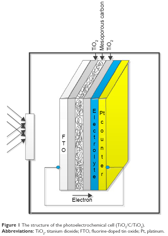 | Figure 1 The structure of the photoelectrochemical cell (TiO2/C/TiO2). |
Results and discussion
Characterization of photoanodes
The XRD patterns of pure TiO2 and TiO2/C with various configurations are presented in Figure 2. In the XRD patterns of TiO2 nanoparticles, the anatase phase was the predominant structure compared with the rutile phase.18 Anatase has a more open crystalline structure, whereas rutile has a compact, rod-like, and crystalline structure as depicted in Figure 3. Studies have also suggested that the anatase phase, due to its open structure, results in a more active and selective catalyst compared with the rutile phase. It is widely believed that anatase is the active phase in photocatalytic reactions.18 All peaks are well indexed as the anatase phase (JCPDS card no 89-4921) in the pure TiO2 sample. The average crystallite size was understood to be 8.29 nm based on the Debye–Scherrer equation:19
|
|

 | Figure 2 XRD results for (a) TiO2, (b) TiO2/C/TiO2, (c) TiO2/C/C/TiO2, and (d) TiO2/C/TiO2/C/TiO2 samples. |
 | Figure 3 A schematic of anatase and rutile phases of TiO2 structure. |
The mean crystallite size can be calculated based on the value corresponding to the maximum peak’s half value. Where λ is the wavelength of the X-ray radiation (λ=0.154056 nm), K is the Scherrer constant (K=0.89), θ is the diffraction angle, and β is the line width at half-maximum height of the most intense peak. A major peak corresponding to (1 0 1) reflections of the anatase phase of TiO2 was apparent at an angle of 25.3°, whereas the minor peaks appearing at 34.50°, 48.5°, 53.5°, and 55.1° represented the indices of (0 0 4), (2 0 0), (1 0 5), and (2 1 1) planes of anatase and TiO2, respectively.
The average crystallite size of anatase TiO2 was calculated from the Debye–Scherrer equation using the (1 0 1) diffraction peak of anatase TiO2 at 25.3°. Upon adding mesoporous carbon content, the peak intensities of mesoporous carbon grew and the anatase phase of TiO2 became stronger, indicating that the crystallinity of the TiO2 anatase was preserved during the addition of the mesoporous carbon layers. The TiO2/C nanocomposites did not show any peak shift, indicating that the TiO2 matrix was well maintained as the anatase phase. By adding mesoporous carbon as an additional layer, some of the diffraction peaks became sharp and narrow while some others became broader. There are distinct peaks in the TiO2/C pattern: one at 25.3° that belongs to the anatase phase of TiO2 and the others occurring at 38° and 43° that belong to graphite.
The SEM images of TiO2, TiO2/C/TiO2, TiO2/C/C/TiO2, and TiO2/C/TiO2/C/TiO2 are shown in Figure 4. Photocatalysts with unique styles of a coating layer (one to five layers) on the FTO substrate were fabricated. The film thickness was measured by SEM, which ranged from 1.605 μm to 5.165 μm. Uncoated FTO thin oxide conductive layers had a thickness of ~820 nm. The coarseness of the surface was different for each synthesized photocatalyst as a result of the incorporation of mesoporous carbon as the intermediate layer. It is clear that the coarseness of the surface increased when the mesoporous carbon was selected as the intermediate layer. The TiO2/C/C/TiO2 sample showed the highest degree of coarseness. This could be the consequence of the presence of two continuous layers of mesoporous carbon providing numerous void space, which can also lead to the enhancement in the absorption of light beams. By the introduction of a mesoporous carbon layer, the coarseness also increased in all three samples compared with pure TiO2. However, with TiO2 as the middle layer (TiO2/C/TiO2/C/TiO2), a reduction in the coarseness of the surface and, consequently, a decrease in photocurrent density was observed. In this case, TiO2 may play a role as a barrier to electron transfer. Obviously, at least three coating layers are crucial for the fabrication of TiO2 photocatalyst. This intermediate layer is required in order to increase the coarse pore structure of the layer and large surface irregularities or defects leading to the dispersion of UV–Vis light. When more than three coatings were further added to the structure, the photocurrent density started to decrease (TiO2/C/TiO2/C/TiO2). It was observed that increasing the layers is not effective for the photocatalytic process, whereas increasing the porous layer (mesoporous carbon) had a strong impact on the photocurrent.
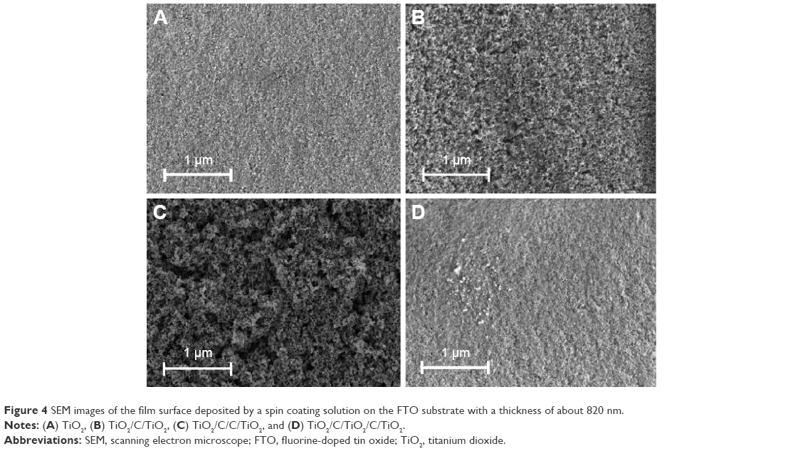 | Figure 4 SEM images of the film surface deposited by a spin coating solution on the FTO substrate with a thickness of about 820 nm. |
N2 adsorption/desorption isotherms (Figure 5) illuminated that mesoporous carbon and TiO2 nanoparticles exhibited a typical type IV isotherm according to the IUPAC classification,20 indicating mesopore-rich textural properties for both samples. In mesoporous carbon, a steep and sharp H1-type hysteresis loop at a high relative pressure (P/P0>0.6) was observed. However, capillary condensation at a low relative pressure (P/P0o ≈0.4) in the TiO2 nanoparticle mesopores was detected. The Brunauer–Emmett–Teller surface area and pore volume of mesoporous carbon and TiO2 nanoparticles are shown in Table 1. In Figure 5, mesoporous carbon possess a high surface area, ie, three times of that of TiO2 nanoparticles. By introducing mesoporous carbon as a sublayer between the TiO2 layers, the photocurrent density could improve due to enhanced surface area and roughness. This could similarly lead to an enhanced efficiency in light absorption.
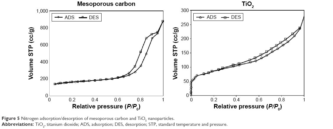 | Figure 5 Nitrogen adsorption/desorption of mesoporous carbon and TiO2 nanoparticles. |
 | Table 1 BET analysis of mesoporous carbon and TiO2 nanoparticles |
Figure 6 shows the AFM images (3D mode) of the surfaces of TiO2 and TiO2/C films. The surface plots of all samples demonstrate that the films are quite rough at the nanometer scale with a granular structure consisting of interconnected grain particles fused together. The particles create indentations and protrusions as seen in Figure 6. The surface roughness increases in the samples with mesoporous carbon as an additional layer. Figure 6 clearly reveals the rough surface of TiO2/C/C/TiO2 in comparison with the other samples. The results are in agreement with the SEM images presented in Figure 4. The low surface roughness for TiO2 implies that the films consist of fine grains and amorphous structures, whereas the large grains were found in the sample with mesoporous carbon. The samples with different layer combinations and styles took on quite different surface morphologies. The surface of TiO2 shows a small degree of roughness and is more homogeneous compared with the samples with mesoporous carbon. AFM results successfully demonstrated the effect of mesoporous carbon on surface roughness.
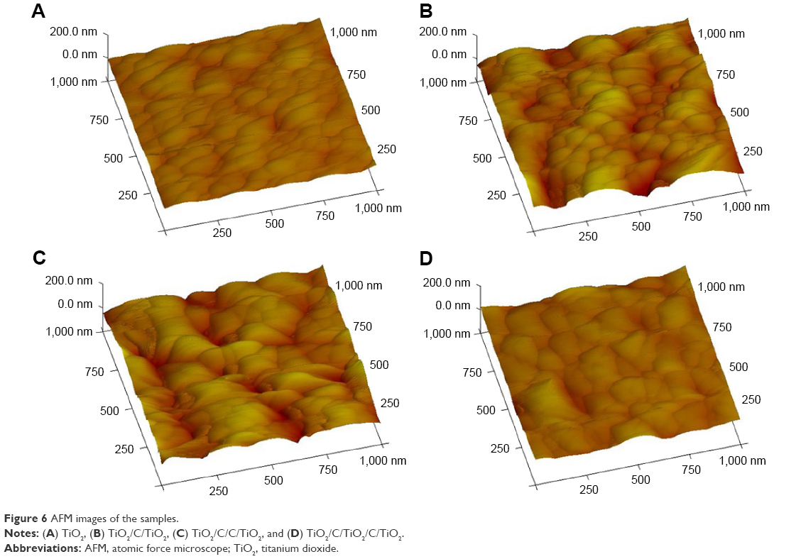 | Figure 6 AFM images of the samples. |
Photocurrent density
Carbons are strong light-absorbing materials and can be employed in the production of photoanodes. Activated carbon–titania composites as photocatalysts have shown high efficiencies for the photodegradation of pollutants.21 Velasco et al investigated the photochemical behavior of activated carbons under UV–Vis light irradiation. They suggested that UV–Vis light could penetrate inside the pores of carbon.14 The carbon/UV–Vis light interactions occur at the carbon surface promoting the photogeneration of charge carriers (electron–hole pairs) that could migrate through the graphitic sheets in the carbon and then transfer to the other layers. Moreover, oxygen functionalities on mesoporous carbon could act as charge injectors upon UV light excitation. Unfortunately, the relationship between the nature of carbon and their photocatalytic activity under UV–Vis light is not well clear. However, the mechanism (electron–hole pairs) in mesoporous carbon may be associated with the porosity of carbon or can be attributed to carbon surface functions. This mechanism is explained by the penetration of UV light into carbon porosity. Moreover, carbon–photon interactions can occur at the external carbon surfaces subsequently propagated through the mesoporous carbon.14,22,23
When carbon is illuminated under UV light, a fraction of the incident photon flux would provoke the generation of charge carriers, which will diffuse randomly through the mesoporous carbon. The role of the graphitic sheets of carbons would be of paramount importance for the migration of the photogenerated electrons, minimizing recombination, and favoring the electron transfer to the other sheets.24 The characteristics of photocurrent density versus photovoltage for the cells are plotted in Figure 7. The corresponding parameters are also presented in Table 2. The surface roughness was enhanced in a sequential fashion, ie, TiO2/C/C/TiO2 > TiO2/C/TiO2 > TiO2/C/TiO2/C/TiO2 > TiO2. This order shows that TiO2/C/C/TiO2 has the highest degree of surface roughness, and therefore, the highest value of photocurrent density was linked to this photoanode. In this case, the porous surface of photoanodes provided high surface area (to absorb maximum light), and a double layer of mesoporous carbon facilitated the rapid transport of charges. Figure 7 confirms that adding a layer of mesoporous carbon could increase the photocurrent density compared with the photoanode fabricated by the TiO2 nanoparticles alone.
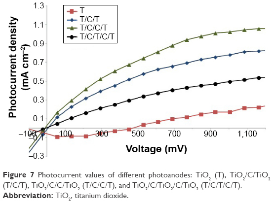 | Figure 7 Photocurrent values of different photoanodes: TiO2 (T), TiO2/C/TiO2 (T/C/T), TiO2/C/C/TiO2 (T/C/C/T), and TiO2/C/TiO2/C/TiO2 (T/C/T/C/T). |
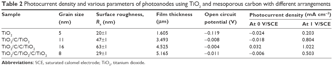 | Table 2 Photocurrent density and various parameters of photoanodes using TiO2 and mesoporous carbon with different arrangements |
The efficiency of TiO2 in solar energy applications is restricted due to the fast photogenerated electron–hole recombination in the UV–Vis light absorption. In the present study, the design of layers is based on thin TiO2/carbon films where the carbon is of mesoporous scale. Mesoporous carbon represents a type of carbon, which is neither perfectly crystalline nor completely amorphous, and is composed of sp2 microstructures lacking a long-range crystalline order. The synthesized carbon is of a porous and amorphous structure with a porosity ranging from <2 nm (micropores) and 2–50 nm (mesoporous) to >50 nm (macropores) with a high surface area. The exact structural mechanism of carbon/TiO2 is not clear, and the addition of carbon in the TiO2 lattice causes a significant bandgap narrowing.25 Zhao et al have studied TiO2 loaded onto activated carbon fibers demonstrating enhanced photocatalytic activity and a red-shift in excitation wavelength (Eg =1.68 eV or 2.10 eV)26 resulting in red shift in the absorption spectrum. This difference in red shift is associated with the carbon location in the lattice, which is dependent on the preparation methods employed. The nature of the carbon dopant state in the TiO2 lattice can be generated in different bonds such as Ti–C or O–Ti–C. It is also demonstrated that the concentration of doped carbon in TiO2 is an important factor for observing the visible light activity of TiO2. Some studies indicated that the dopant states of carbon in TiO2 are highly undesirable because they promote a charge carrier recombination.27 Some studies have pointed out that the enhanced activity was attributed to improved charge carrier separation at the interface between the carbon and the TiO2 films.28
Mesoporous carbon could promote photocatalytic activity due to the higher surface area of the composites (C/TiO2) and consequently absorption of more light beams. Mesoporous carbon can provide good electronic properties in the C/TiO2 composites. Therefore, carbon with more homogeneity in structure has a large electron-storage capacity (one electron for each 32 carbon atoms) and a fast transmission rate of photogenerated electrons. Moreover, the photogenerated electrons are transferred from the TiO2 conduction band toward the carbon surface due to a lower Fermi level. Some of the proposed effects contributing to better photocatalytic performance (TiO2/C) were suggested by Sellappan et al,28 which are illustrated in Figure 8.
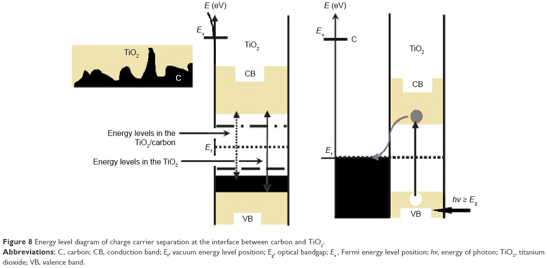 | Figure 8 Energy level diagram of charge carrier separation at the interface between carbon and TiO2. |
Furthermore, in the presence of carbon, the photogenerated electrons on TiO2 can continuously move to the carbon surface, spatially separating the electron and the hole, thus, effectively decreasing recombination.29,30 Adding mesoporous carbon may affect charge carrier dynamics and, in turn, affect photocatalytic activity.
Experiments on pure TiO2 show a decrease in photocurrent density at low voltages. Current density is the sum of the capacitive and ionic components. For TiO2, the capacitive behavior appeared at low voltages (negative current), whereas the capacitive current is zero for photoanodes containing TiO2 and mesoporous carbon. A negative current value or downward deflection of a current trace is typically referred to as an inward current. A negative current value (ie, inward current) can reflect either the movement of positive ions (cations) or negative ions (anions). O−2 anions (from the water content) are diffusing inward into the metallic surface (TiO2) and, thus, a growth of an anodic layer can take place leading to the ejection of a great number of electrons, ie, generating the highest electronic current response. So the current decays during the first minutes of reaction. Mesoporous carbon as an intermediate layer can act as a current collector to prevent capacitive current.
Adsorption study
HA is a major type of dissolved organic matter that contains a variety of functional groups such as aromatic units, amide, amine, and various oxygen-containing groups. HA adsorption was studied and compared by using two photoanodes (with C and without C). The amount of HA obtained from adsorption can be calculated by measuring the HA concentration at each time interval. As soon as the system reached equilibrium, the HA concentration was measured using a UV–Vis spectroscope. The effect of pH on HA removal was studied within a pH range of 4–10 by using TiO2/C/C/TiO2 as photoanode. The results are presented in Figure 9. The adsorption attains an optimum at pH 5 for the adsorption of HA on photoanodes. Two photoanodes (TiO2 and TiO2/C/C/TiO2) were employed in order to adsorb HA. This was due to the fact that these two photoanodes corresponded to producing the minimum and maximum current densities, respectively. The HA removal performances by both TiO2/C/C/TiO2 and TiO2 are shown in Figure 10. The adsorbed HA indicated that TiO2/C/C/TiO2 had a higher efficiency compared with TiO2. This shows that TiO2/C/C/TiO2, having both the highest degree of surface roughness and the porous surface area, provides the maximum light absorption efficiency.
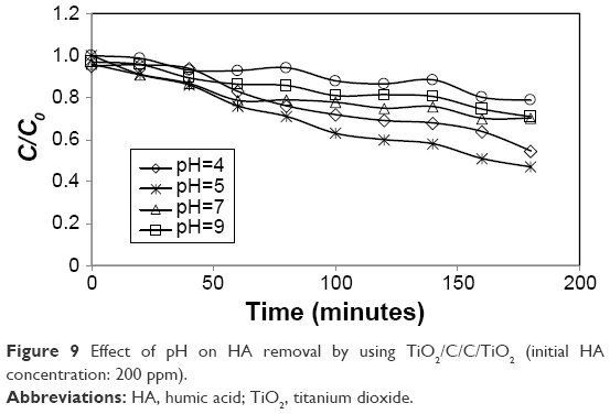 | Figure 9 Effect of pH on HA removal by using TiO2/C/C/TiO2 (initial HA concentration: 200 ppm). |
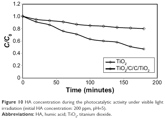 | Figure 10 HA concentration during the photocatalytic activity under visible light irradiation (initial HA concentration: 200 ppm, pH=5). |
The decay rate of the HA concentration was found to follow a pseudo first-order reaction. The rate could be determined by the following integrated first-order decay expression:
|
|

The adsorption capacity at equilibrium (qe, mg/g) was determined by using:
|
|

where C0 and Ce (mg/L) are the initial and equilibrium concentrations of HA, respectively, m (g) is the mass of adsorbent, and V (L) is the volume of adsorbate solution.
In the present study, TiO2/C/C/TiO2 had a photocurrent higher than pure TiO2, partly due to its larger specific surface area as well as larger porous surface area. A comparative study of the photocatalytic activity of the mesoporous sample with the bulk sample (TiO2) indicated the importance of mesoporosity on the recombination of excited charge carriers and photocatalysis. These results demonstrated that the migration of the photoexcited electrons and the holes in the mesoporous sample and bulk sample should be quite different due to significant differences in surface structure.
Conclusion
Mesoporous carbon with high surface area and porosity was employed in the synthesis of multilayered photoanodes. Two different types of photoanodes were tested in order to investigate the effect of mesoporosity of carbon on photocurrent intensity and surface roughness. A higher photocurrent density was observed with double layers of mesoporous carbon between TiO2 when compared with only one layer of mesoporous carbon. A double layer of mesoporous carbon between TiO2 also gave a higher degree of surface roughness in comparison with one layer of mesoporous carbon. A significant enhancement in photocurrent was measured by adding additional layers as seen for the two photoanodes: TiO2/C/TiO2 and TiO2/C/TiO2/C/TiO2. The addition of two carbon layers increased the graphite sheets between the TiO2 layers. The graphite sheets may have facilitated rapid transport of charges or contributed to the generation of charged carriers due to the functional groups of mesoporous carbon. Adsorption coupled with a photocatalytic process was used here as an economic approach for waste water treatment, such as the removal of HA. A comparative study of the photocatalytic activity of two photoanodes (TiO2/C/C/TiO2 and TiO2) demonstrated that the mesoporosity of carbon and the recombination of excited charge carriers could increase HA removal.
Acknowledgment
The authors would like to acknowledge High Impact Research (grant number HIR/MOE/ENG59), University of Malaya, Kuala Lumpur, Malaysia, and Northeastern University, Boston, MA, USA, for their earnest cooperation of this research.
Disclosure
The authors report no conflicts of interest in this work.
References
Rodriguez P, Meille V, Pallier S, Al Sawah MA. Deposition and characterisation of TiO2 coatings on various supports for structured (photo) catalytic reactors. Appl Catal A Gen. 2009;360:154–162. | ||
Antoniou MG, Nicolaou PA, Shoemaker JA, De la Cruz AA, Dionysiou DD. Impact of the morphological properties of thin TiO2 photocatalytic films on the detoxification of water contaminated with the cyanotoxin, microcystin-LR. Appl Catal B Environ. 2009;91:165–173. | ||
Matos J, Chovelon JM, Cordero T, Ferronato C. Influence of surface properties of activated carbon on photocatalytic activity of TiO2 in 4-chlorophenol degradation. Open Environ Eng J. 2009;2:21–29. | ||
Akpan UG, Hameed BH. The advancements in sol–gel method of doped-TiO2 photocatalysts. Appl Catal A Gen. 2010;375:1–11. | ||
Pereira L, Pereira R, Oliveira CS, et al. UV/TiO2 photocatalytic degradation of xanthene dyes. Photochem Photobiol. 2013;89(1):33–39. | ||
Daghrir R, Drogui P, Robert D. Modified TiO2 for environmental photocatalytic applications: a review. Ind Eng Chem Res. 2013;52(10):3581–3599. | ||
Fateh R, Dillert R, Bahnemann D. Preparation and characterization of transparent hydrophilic photocatalytic TiO2/SiO2 thin films on polycarbonate. Langmuir. 2013;29(11):3730–3739. | ||
Leshuk T, Parviz R, Everett P, Krishnakumar H, Varin RA, Gu F. Photocatalytic activity of hydrogenated TiO2. ACS Appl Mater Interfaces. 2013;5(6):1892–1895. | ||
Chen Y, Lee C, Yeng M, Chiu H. Preparing titanium oxide with various morphologies. Mater Chem Phys. 2003;81:39–44. | ||
Yang E, Shi JJ, Liang H, Cheuk W. Coaxial WO3/TiO2 nanotubes/nanorods with high visible light activity for the photodegradation of 2,3-dichlorophenol. Chem Eng J. 2011;174:539–545. | ||
Choudhary S, Upadhyay S, Kumar P, et al. Nanostructured bilayered thin films in photoelectrochemical water splitting: a review. Int J Hydrogen Energy. 2012;37:18713–18730. | ||
Memar A, Wan Daud WR, Hosseini S, Eftekhari E, Jeffery Minggu L. Study on photocurrent of bilayers photoanodes using different combination of WO3 and Fe2O3. Solar Energy. 2010;84:538–1544. | ||
Sivula K, Le Formal F, Gratzel M. WO3-Fe2O3 photoanodes for water splitting: a host scaffold, guest absorber approach. Chem Mater. 2009;21:2862–2867. | ||
Velasco LF, Fonseca IM, Parra JB, Lima JC, Ania CO. Photochemical behaviour of activated carbons under UV Irradiation. Carbon N Y. 2012;50:249–258. | ||
Yang J, Zhang Z, Men X, Xu X, Zhu X. Reversible superhydrophobicity to superhydrophilicity switching of a carbon nanotube film via alternation of UV irradiation and dark storage. Langmuir. 2010;26(12):10198–10202. | ||
Pan JH, Lei Z, Lee WI, Xiong Z, Wang Q, Zhao XS. Mesoporous TiO2 photocatalytic films on stainless steel for water decontamination. Catal Sci Technol. 2012;2:147–155. | ||
Memar A, Phan CM, Tade MO. Influence of surfactants on Fe2O3 nanostructure photoanode. Int J Hydrogen Energy. 2012;37:16835–16843. | ||
Garcia J, Deskins NA. First Principles Modeling of TiO2 Rutile/Anatase Interfaces, Catalysis and Reaction Engineering Division. Proceedings of the 2012 Annual Meeting of the American Electrophoresis Society (AES). 2012; Pittsburgh, PA. | ||
Hosseini S, Mohamad AB, Wan Daud WR, Kadhum AAH. Surfactants effect in the synthesis of CsH2PO4 as protonic conductive membrane in fuel cell. Bull Mater Sci. 2011;34:1–7. | ||
Hosseini S, Alii Khan M, Malekbala MR, Cheah W, Choong TSY. Carbon coated monolith, a mesoporous material for the removal of methyl orange from aqueous phase: adsorption and desorption studies. Chem Eng J. 2011;171:1124–1131. | ||
Liang YT, Vijayan BK, Lyandres O, Gray KA, Hersam MC. Effect of dimensionality on the photocatalytic behavior of carbon–titania nanosheet composites: charge transfer at nanomaterial interfaces. J Phys Chem Lett. 2012;3(13):1760–1765. | ||
Kumar SG, Devi LG. Review on modified TiO2 photocatalysis under UV/visible light: selected results and related mechanisms on interfacial charge carrier transfer dynamics. J Phys Chem A. 2011;115(46):13211–13241. | ||
Liu S, Guo E, Yin L. Tailored visible-light driven anatase TiO2 photocatalysts based on controllable metal ion doping and ordered mesoporous structure. J Mater Chem. 2012;22:5031–5041. | ||
Tascon J. Novel Carbon Adsorbents. Amsterdam: Elsevier; 2012. | ||
Serpone N. Is the band gap of pristine TiO2 narrowed by anion- and cation-doping of titanium dioxide in second-generation photocatalysts? J Phys Chem B. 2006;110(48):24287–24293. | ||
Zhao W, Bai Z, Ren A, Guo B, Wu C. Sunlight photocatalytic activity of CdS modified TiO2 loaded on activated carbon fibers. Appl Surf Sci. 2010;256(11):3493–3498. | ||
Neumann B, Bogdanoff P, Tributsch H, Sakthivel S, Kisch H. Electrochemical mass spectroscopic and surface photovoltage studies of catalytic water photooxidation by undoped and carbon-doped titania. J Phys Chem B. 2005;109(35):16579–16586. | ||
Sellappan R, Galeckas A, Venkatachalapathy V, Kuznetsov AY, Chakarov D. On the mechanism of enhanced photocatalytic activity of composite TiO2/carbon nanofilms. Appl Catal B Environ. 2011;106:337–342. | ||
Zhang H, Lv XJ, Li YM, Wang Y, Li JH. P25-graphene composite as a high performance photocatalyst. ACS Nano. 2010;4(1):380–386. | ||
Zhang LW, Fu HB, Zhu YF. Efficient TiO2 photocatalysts from surface hybridization of TiO2 particles with graphite-like carbon. Adv Funct Mater. 2008;18:2180–2189. |
 © 2016 The Author(s). This work is published and licensed by Dove Medical Press Limited. The
full terms of this license are available at https://www.dovepress.com/terms
and incorporate the Creative Commons Attribution
- Non Commercial (unported, 3.0) License.
By accessing the work you hereby accept the Terms. Non-commercial uses of the work are permitted
without any further permission from Dove Medical Press Limited, provided the work is properly
attributed. For permission for commercial use of this work, please see paragraphs 4.2 and 5 of our Terms.
© 2016 The Author(s). This work is published and licensed by Dove Medical Press Limited. The
full terms of this license are available at https://www.dovepress.com/terms
and incorporate the Creative Commons Attribution
- Non Commercial (unported, 3.0) License.
By accessing the work you hereby accept the Terms. Non-commercial uses of the work are permitted
without any further permission from Dove Medical Press Limited, provided the work is properly
attributed. For permission for commercial use of this work, please see paragraphs 4.2 and 5 of our Terms.