Back to Journals » Journal of Pain Research » Volume 13
Sensing Evoked Compound Action Potentials from the Spinal Cord: Novel Preclinical and Clinical Considerations for the Pain Management Researcher and Clinician
Authors Chakravarthy K, Bink H, Dinsmoor D ![]()
Received 28 October 2020
Accepted for publication 25 November 2020
Published 4 December 2020 Volume 2020:13 Pages 3269—3279
DOI https://doi.org/10.2147/JPR.S289098
Checked for plagiarism Yes
Review by Single anonymous peer review
Peer reviewer comments 2
Editor who approved publication: Dr Micheal Schatman
Krishnan Chakravarthy,1 Hank Bink,2 David Dinsmoor2
1Anesthesiology and Pain Management, University of California San Diego, San Diego, CA, USA; 2Neuromodulation, Medtronic Plc, Minneapolis, MN, USA
Correspondence: David Dinsmoor
Medtronic Plc, 7000 Central Ave NE RCE470, Minneapolis, MN 55432, USA
Tel +1 763 526-8801
Email [email protected]
Purpose: Spinal cord stimulation (SCS) is a drug-free treatment for chronic neuropathic pain. Recent SCS technology can record evoked compound action potentials (ECAPs) in the spinal cord during therapy and utilize features of the sensed ECAP to optimize the SCS. The purpose of this work is to characterize the relevant parameters that govern the integrity and morphology of acquired ECAPs, and the implications for pain management clinicians and researchers working with ECAPs.
Materials and Methods: Eight-contact percutaneous SCS leads were implanted into sheep, and a prototype ECAP-sensing system was used to record spinal cord activity across a range of electrode configurations, pulse widths, and stimulus amplitudes. Similar iterative testing was then completed in human subjects who were undergoing trials of commercial SCS systems.
Results: Longer pulse width stimulation results in a progressive increase in ECAP latency, a neurophysiologic effect that enables ECAP sensing with longer pulses despite more encroachment by stimulation artifact. ECAPs may manifest a polyphasic morphology—an effect not seen in all subjects studied—with longer pulse width stimulation; these later phases may be used to assess ECAP amplitude when earlier features are effaced by artifact. Triphasic stimulation limits artifact from spinal cord ECAPs at the expense of potentially higher activation thresholds. If applied, alternating polarity stimulation must account for the ECAP latency differences resulting from alternating sites of neural activation.
Conclusion: Together, this information can allow the ECAP to be readily distinguished from the stimulation artifact, although movement may continue to be a confounder; caution is inculcated for ECAP signal processing techniques that rely on the stability of the artifact to avoid clinically misleading results. The promise of closed-loop, ECAP-servoed neuromodulation relies on accurate and proper sensing of the ECAP, while clearly elucidating the clinically relevant trade-offs and design choices made to enable these novel features.
Keywords: neuromodulation, closed-loop control, artifact, pulse width, biopotential
Introduction
Spinal cord stimulation (SCS) has been used as a treatment for chronic pain, typically of the axial back or lower extremities since first employed clinically in 1967.1 Historically, these therapeutic interventions have been used to induce paresthesia to create analgesia via the so-called “pain-gate” mechanism in the dorsal columns of the spine.2 Newer approaches for SCS have taken a more sophisticated approach by focusing on electrical modulation of pain-relevant biochemical and molecular processes.3,4
Most recently, paresthesia-based SCS has been enhanced further with the introduction of evoked compound action potential (ECAP) servoed, closed-loop technology.5 The ECAP is an electrophysiological signal often described as a triphasic biopotential—consisting of a first peak (P1), then a negative trough (N1), followed by a second peak (P2) — representing the synchronized firing of a population of axons in the spinal cord in response to an electrical stimulus.6 ECAPs may include additional phases as well depending on which neural structures are activated; polyphasic ECAPs have been recorded from other parts of the body, such as the cochlea.7 Control of neural activation in the spinal cord by sensing, and responding to, the ECAP may afford better opportunities for a more durable therapy, particularly when multiple therapeutic modalities are used.
A major challenge associated with acquiring ECAPs is reliably sensing small-amplitude signals in the presence of large-amplitude stimulation artifacts and other sources of electrical and physiological noise.8 Methods that can be employed for ECAP sensing in the spinal cord were inspired by the methods first developed for analyzing ECAPs collected by cochlear implants (CIs).9 Some of these techniques include forward masking, higher electrode counts versus conventional SCS devices, tripolar stimulation, and alternating polarity stimulation.10 Considerable differences exist, however, in the sensing environment between the inner ear and spinal canal. In CIs, the electrode-neural target interface is static and electrodes are placed in proximity (≤0.5 mm) to their target, which is likely to result in recordings with artifacts that are consistent over time.11,12 In contrast, SCS leads are placed in the mobile spine where the thickness of the interposing layer of cerebrospinal fluid (CSF) can vary with movement and position (eg, the dorsal CSF layer at T11 is 3.6 mm while supine and 5.8 mm while prone).13,14 This suggests that, compared to CIs, ECAP detection in SCS may be vulnerable to physical perturbations in signal detection. Any methods employed by ECAP-sensing SCS systems must be properly validated to ensure the system does not inappropriately classify stimulation artifact or other electrical phenomena as ECAPs. Such issues, including signal contamination with stimulation artifact due to matched-filter correlation signal processing methods, have been identified as challenges in quantification of spinal cord activation, and would ideally be avoided in robust SCS sensing systems.15
While recent work has focused on the clinical benefit of proprietary closed-loop SCS systems, characterizations of ECAP waveforms themselves have been oriented more towards understanding the electrophysiologic basis of the ECAP with graded amplitude stimulation and a limited set of stimulation pulse widths.16–19 Further, much of the predicate work was done using atypical dual “linear” lead placements versus a more clinically relevant, single- or dual-staggered placements.20 In this paper, therefore, we more completely address the considerations relevant to SCS ECAP-sensing assurance and the utility of some of the aforementioned approaches leveraged from the CI space. These factors are examined by exploring the ECAP signals elicited by SCS in sheep—a model used previously for studying ECAPs acutely in the spinal cord, but extended in this paper to a novel, unanesthetized chronic model with externalized lead access —and in awake humans, and comparing outcomes between the animal models and humans.18 Specific attention is given to characterizing increased ECAP latency seen with progressively widened stimulation pulses, and the conditions under which the ECAP may transition from a triphasic to polyphasic morphology. While not designed for statistical power, our results nevertheless elucidate the factors—particularly stimulation pulse width and stimulation/sensing electrode configuration on standard SCS leads—relevant to both the engineers and researchers designing systems with spinal cord ECAP sensing, as well the clinicians interpreting the results of such systems.
Materials and Methods
This study consisted of preclinical and clinical components. All preclinical work was approved by the Medtronic Institutional Animal Care and Use Committee. The animals were cared for according to Medtronic Physiological Research Laboratories Standard Operating Procedures, and the current versions of both “The Guide for Care and Use of Laboratory Animals” and “The Guide for the Care and Use of Agricultural Animals in Research and Teaching.”21,22 All human clinical work was approved by Western Institutional Review Board and was conducted in accordance with the Declaration of Helsinki. The clinical component of this US-based study was exempt from registration per §402(j) of the Public Health Service Act, given the small sample size and the prototype equipment employed. Written informed consent from each human subject was obtained.
Stimulation and Recording Equipment
The system employed for delivering electrical stimulation and sensing neural signals in sheep consisted of multiple discrete components. Leads (described below) were connected into the system with a Multi-Lead Trialing Cable (MLTC model #3555-31, Medtronic). A custom MLTC adapter was used to multiplex the electrodes for stimulation and recording into the rest of the instrumentation. Balanced, biphasic stimulation waveforms were synthesized with a waveform generator (Keysight 33511B) and passed through a clinical-grade, isolated bipolar stimulator (Digitimer DS5). The sensed signals were amplified and filtered with a clinical-grade amplifier (Digitimer D440). The amplifier was intentionally left unblanked during stimulation to allow for later characterization of the artifact.23 After amplification, the sensed signals were digitized (Biopac MP160) and stored on a laptop (Biopac AcqKnowledge).
The system used for humans differed slightly, using National Instruments hardware to configure and deliver stimulation waveforms to the isolator, and record evoked signals from the amplifier in place of the Biopac MP160. Custom software (National Instruments LabVIEW) was developed to control the stimulation and recording parameters.
Both systems could deliver stimulation in tripolar or bipolar configurations. Sensing was performed on two bipoles on a single lead. Stimulation consisted of charge-balanced, biphasic pulses with selectable pulse widths from 30 µs to 1 ms and a 30-µs interphase interval delivered at a pulse frequency of 50 Hz. The constant-current stimulation amplitude could be swept up to ±25 mA at a resolution of 0.01 mA. Physiological recordings were analyzed and processed off-line (Mathworks MATLAB).
Animal Preparation
Two female Polypay sheep, sheep A (56 months, 82 kg) and sheep B (41 months, 97 kg), were chronically implanted with commercially available, 60 cm 1×8 percutaneous SCS leads midline near T9. Sheep A’s lead had 9 mm electrode-to-electrode spacing, or pitch (model #3777-60, Medtronic), and Sheep B’s lead had narrower pitch at 7 mm (model #3778-60, Medtronic). Different electrode pitches were deliberately employed to help illustrate comparative commonalities and differences in ECAP amplitude, latency, and artifact phenomena with electrode pitch. These leads were introduced without difficulty using a standard, percutaneous technique with an epidural spine needle placed through the foramen at the thoracolumbar junction, despite this method being described as not possible in ovines.18 Following the anchoring of the leads at the entry point (longissimus dorsi muscle), a strain relief loop was made in the vicinity and each lead was connected to an extension (model #37081, Medtronic) which was tunneled cranially under the skin. The proximal end of the lead extensions was exteriorized over the dorsal thorax. A second strain relief loop was made under the skin at the extension exit incisions, then each extension was secured to the fascia using a roman sandal suture just before exiting the skin. The animals wore spandex sheep tubes after lead implant to prevent damage to the exteriorized portion of the extensions, which were successfully maintained without infection. ECAP testing used a single lead for each sheep, up to 12 months after implantation.
Preclinical Stimulation and ECAP Sensing
The stimulation system was configured to stimulation with pulse widths from 30 µs to 300 µs in 30-µs steps. As neural activation with SCS is a function of both stimulation amplitude and pulse width, these parameters were co-varied to result in an equivalent charge of 75 nC/phase.24 Previous work was limited to graded amplitude stimulation amplitude with pulse widths of 40 µs, 80 µs, or 120 µs.17 The stimulation was delivered in two different bipolar configurations and one tripolar configuration. In the first bipolar configuration, the leading cathodic phase was delivered at E7 with respect to E6—this configuration is denoted as E7−/E6+. The electrodes were reversed for the second bipolar configuration as E7+/E6−. The tripolar configuration consists of a center cathode at E6 with equal charge return to E7/E5 (E7+/E6−/E5+). Two channels of differential recording were connected concurrently on E1/E0 and E2/E1. Stimulation pulse parameters, and the electrodes used for simultaneous stimulation and recording, are shown in Figure 1.
 |
Figure 1 Stimulation patterns and electrode configurations for testing in sheep. (A)Exemplary stimulation pulses. Each carries a constant charge of 75 nC/phase (eg, biphasic pulse of 30 μs at 2.5 mA). (B) Schematic diagrams of the percutaneous lead and the location of bipolar or tripolar stimulating electrode configurations. Amplifier connections for recording spinal cord potentials, represented on the bottom-most diagram, were placed at the opposite end of the lead. |
Biopotential recordings—consisting of stimulation artifact plus an ECAP, if present—were taken from awake sheep in a single pass. Assessing run-to-run variability was not an objective of this study. The sheep were suspended in slings to limit movement between the cord and leads. After a one-minute stimulation wash-in period, biopotentials were averaged at each stimulation amplitude/pulse width combination. A stimulation wash-out of at least 1 minute was employed between different measurements. All measurements and data analyses were performed identically between sheep; no specific randomization or investigator blinding was otherwise employed.
Clinical Stimulation and ECAP Sensing
Subjects undergoing commercial SCS trialing according to approved labeling were consented and enrolled in the study, a feasibility study assessing stimulation and sensing methods relevant to closed-loop SCS control. All leads used in this study were conventional 60 cm, 1×8 percutaneous leads with 7 mm spacing (model #977D260, Medtronic). Immediately prior to lead explant at the end of a commercial trial, the subject’s leads were connected to the study system described above. While all subjects had two staggered leads, stimulation was delivered to, and recordings were made from, a single lead at a time. Stimulation amplitudes were progressively increased up to the discomfort threshold—the point at which the stimulation would not be comfortably tolerated for more than 30 seconds—while monitoring ECAP recordings and the qualitative subject responses. This process was repeated with various stimulation parameters and with the subject in different postures or performing specified activities, such as a back arch, that result in variation in the lead-cord spacing. Swept pulse width stimulation was assessed in five subjects, and stimulation artifact with motion and triphasic versus biphasic stimulation was assessed in another two subjects, respectively. The resultant ECAPs and stimulation artifacts were then analyzed using methods similar to those employed with the preclinical data. Following data collection, the subject was disconnected from the study system. Treatment with the commercial SCS system, including removal of trial leads, proceeded according to standard of care.
Results
Preclinical ECAP Characterization
Polyphasic ECAPs were captured in both sheep. Shown in Figure 2A are example biopotentials elicited with bipolar stimulation on E6−/E7+ and sensing on E2/E1. The ECAPs are preceded by a stimulation artifact that obscures P1 (only partially visible at 30 µs pulse width in Sheep A, orange) and progressively effaces N1 as the pulse width is widened. Encroachment of the stimulation artifact on the ECAP is more pronounced in the sheep with the tighter electrode pitch (Sheep B, blue). Iterative increases in the stimulation pulse width results in three changes to the ECAP profile: a longer-latency component of the ECAP, labeled as N2/P3, that manifests at longer pulse widths (ie, 120 µs and higher); a decrease in the resolvable N1-P2 amplitude (Figure 2B), and an increase in the latency from the leading edge of the stimulation pulse to the P2 feature of the ECAP (Figure 2C).
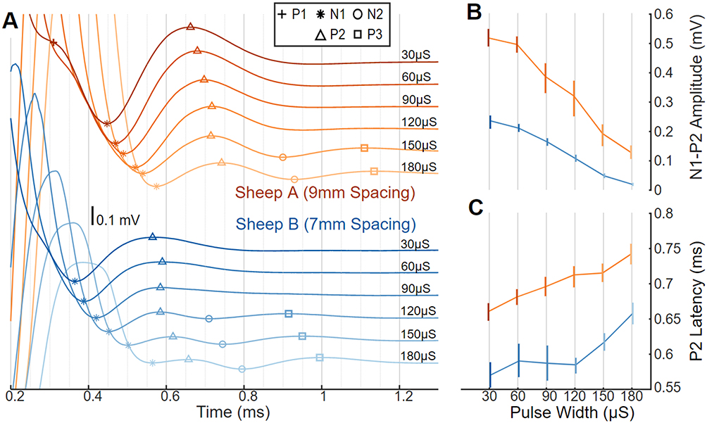 |
Figure 2 ECAPs, with amplitude and latency differences as a function of pulse width in sheep. (A) ECAP variability in two sheep with stimulus pulse width swept from short (30 μs; darker lines) to long (180 μs; lighter lines) and offset vertically. Stimulation was on E7+/E6− at a constant charge of 75 nC/phase and recording on E2/E1; Sheep A (top; orange) used 9 mm spaced electrodes and Sheep B (bottom; blue) used 7 mm spaced electrodes. Symbols indicate location of P1 (+), N1 (*), P2 (Δ), N2 (○), and P3 (□). (B) The N1-P2 amplitude differences plotted versus pulse width with median and 10th-90th percentile range. (C) ECAP latency differences plotted versus pulse width with median and 10th–90th percentile range. |
Selection of a tripolar stimulation configuration (E7+/E6−/E5+) results in a much smaller stimulation artifact versus bipolar stimulation (both E7−/E6+ and E7+/E6−), as is plainly evident in the example from Sheep A in Figure 3A. This reduction in stimulation artifact with tripolar stimulation, however, is at the expense of somewhat smaller ECAP amplitudes. Shown in Figure 3B are relative comparisons of both N1-P2 amplitudes and stimulation artifact peak-to-peak amplitudes for both Sheep A (9-mm electrode spacing, orange) and Sheep B (7-mm electrode spacing, blue) for 30 µs stimulation. Despite employing the same stimulating cathodes (E6) and sensing electrodes (E1/E0), the ECAP amplitudes from tripolar E7+/E6−/E5+ stimulation are suppressed by 20% in Sheep A and 30% in Sheep B when normalized against the ECAPs elicited in the same animals with E7+/E6− stimulation. The smaller ECAP amplitudes with tripolar versus bipolar stimulation presumably result from a smaller volume of neural activation with the former. Stimulation artifact suppression with tripolar stimulation is more variable between the sheep. When normalized against the peak-to-peak artifact measured with E7−/E6+ stimulation, tripolar stimulation results in stimulation artifact suppression of 70% suppression in Sheep A and 35% in Sheep B.
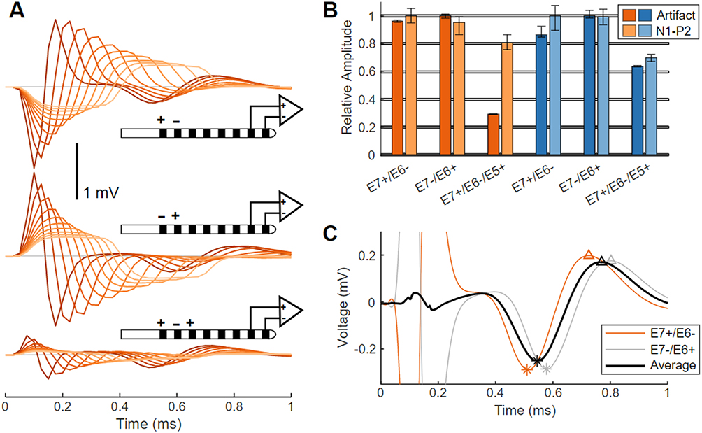 |
Figure 3 Artifact and ECAP variation with stimulating electrode configuration in sheep. (A) Average ECAPs from Sheep A elicited by bipolar stimulation (E7+/E6−, top traces; or E7−/E6+, middle traces), and by tripolar stimulation (E7+/E6−/E5+, bottom traces). Stimuli pulse widths are swept from 30 μs (darker lines) to 300 μs (lighter lines) in 30 μs steps. (B) Normalized ECAP amplitudes and stimulation artifacts for E7+/E6−, E7−/E6+, and E7+/E6−/E5+ stimulation are plotted versus pulse width as median and 10th–90th percentile range, for Sheep A (orange) and Sheep B (blue). (C) ECAPs recorded on E1/E0 in Sheep A in response to 30 us stimulation from E7+/E6− (orange) and E7−/E6+ (gray) as well as the average of both waveforms (black). Slight differences in peak locations (N1 (*), P2 (Δ)) are evident between the ECAPs elicited by the two bipolar configurations. |
Reversing the cathode and anode in bipolar configurations results in a flipped polarity stimulation artifact but identical ECAP polarity (Figure 3A). The ECAP latency is longer by 75 µs when stimulating with E7−/E6+ versus E7+/E6−; this is because the cathode is further from the recording pair in the former case versus the latter. These results are shown in Figure 3C for 30 µs stimulation for both configurations, along with the arithmetic mean.
Clinical ECAP Characterization
Swept pulse width stimulation in humans also results in encroachment of the stimulation artifact on the N1/P2 ECAP complex, consistent with the observations in sheep. This effect is shown in Figure 4A for two seated subjects (Subject #1, purple, and Subject #2, green); in these examples, stimulation is delivered “at comfort” on E7+/E6−/E5+ with recording on E1/E0. Stimulation “at comfort” was subjectively assessed by each subject for each stimulation amplitude/pulse width combination tested. Later-phase components of the ECAP were absent in Subject #1, and more apparent in Subject #2. The encroachment of the artifact on the ECAP is mitigated in part as the latency between the leading edge of the stimulation pulse and the P2 feature of the ECAP increases with longer pulse widths, as is shown with the five subjects (Subject #1 and #2, with Subjects #3 (gray), #4 (red), and #5 (blue)) in Figure 4B. Shown in Table 1 are the pulse widths and charge/phase range used for each subject in Figure 4B, as well as the median increase in ECAP latency between stimulation at 150 µs and 300 µs.
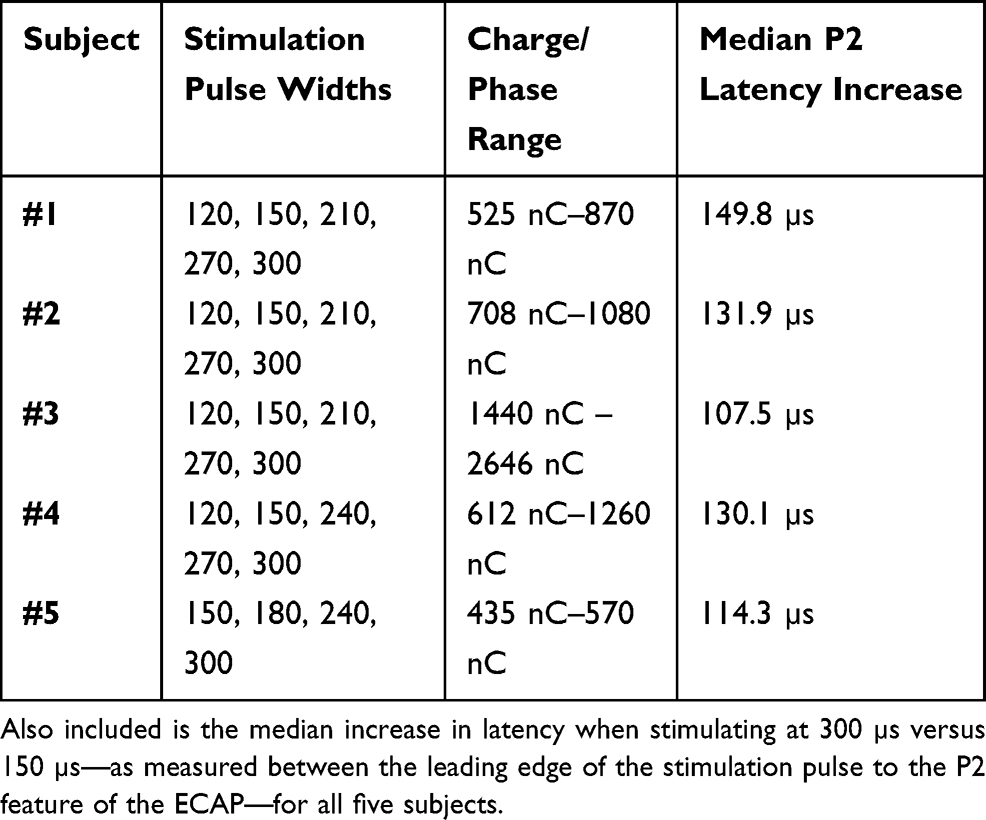 |
Table 1 Stimulation Pulse Widths Tested, Along with the Range of Charge/Phase Used “At Comfort” for Each Subject in Figure 4B |
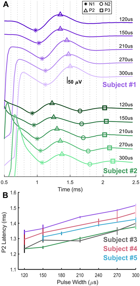 |
Figure 4 ECAPs and latency differences as a function of stimulation pulse width in humans. (A) Swept pulse width (120, 150, 210, 270, and 300 μs) stimulation at a comfortable amplitude on E7+/E6−/E5+ with recording on E1/E0 in two seated subjects, Subject #1 (purple) and Subject #2 (green). Symbols indicate location of N1 (*), P2 (Δ), N2 (○), and P3 (□) as appropriate on the ECAPs. (B) ECAP latency differences are plotted versus pulse width with median and 10th–90th percentile range for Subjects #1 and #2, as well as #3 (gray), #4 (red) and #5 (blue); not all pulse widths were tried in all subjects. |
Whereas the ECAPs are easily resolvable from the stimulation artifact in Figure 4, the artifact may be highly variable when the subject is mobile. This variability is most evident for the exponential component of the artifact (the residual artifact) which occurs after the stimulation pulse has been fully delivered. In Figure 5, 120 µs, fixed-amplitude, sub-threshold stimulation was delivered to Subject #6 on E7+/E6−/E5+ with recording on E1/E0 while the subject was asked to bend at the waist. This stimulation did not produce ECAPs, but readily apparent in this figure are the amplitude, polarity, and time constant differences that occur in the residual artifact across the postural change.
 |
Figure 5 Stimulation artifact recorded with sub-threshold stimulation during a waist bend in clinical Subject #3. The color of the trace (left) corresponds to the color of the subject’s posture (right). No ECAP is present in these recordings, but a variable residual artifact manifests across the postural change. |
Tripolar stimulation may be used in humans to partly mitigate the effects of the stimulation artifact, in a manner like that seen in sheep with Figure 3. In Figure 6, stimulation using 90 µs pulse widths at 6.6 mA was delivered in both bipolar and tripolar configurations to Subject #7 with the cathode at a common location (E6) for both. Peak-to-peak artifacts are decreased from 5.7 mV with bipolar stimulation to 2.2 mV with tripolar stimulation (Figure 6A). ECAP amplitudes are about 8–10 µV for both configurations (Figure 6B).
 |
Figure 6 Stimulation using 90 μs pulse widths at 6.6 mA delivered to both E7+/E6− and E7+/E6−/E5+ in clinical Subject #4 with recording on E1/E0. (A) Extent of entire artifact shows that peak-to-peak artifacts are decreased from 5.7 mV with bipolar stimulation to 2.2 mV with tripolar stimulation. (B) The plot in A is zoomed in to best appreciate the residual artifact and ECAP, which is approximately 8–10 μV in amplitude. |
Discussion
Different sets of challenges exist for recording ECAPs in sheep and human spinal cords. The ECAP in sheep occurs sooner with respect to the stimulation artifact than it does humans, owing to the higher conduction velocities and more limited change in ECAP latency versus stimulation pulse width (Figure 2C vs Figure 4C).18 However, sensing in humans is in general more challenging owing to the larger artifacts and smaller ECAP signal amplitudes. The larger artifacts result from the higher stimulation amplitudes needed to elicit evoked responses in humans, while the smaller signal amplitudes likely result from the thicker CSF layer between the electrodes and the spinal cord in humans versus sheep.17
Confounding spinal cord ECAP sensing even further in humans is the fact that the artifact is highly dependent on movement and body position, as evidenced in Figure 5. Common signal processing techniques, such as matched filtering and template subtraction, which have been successfully applied in some cases to CIs, rely on the consistency of the stimulus artifact. The translatability of these approaches from CI to spinal cord ECAP sensing is limited given the degree of artifact variability, particularly when characteristics of the ECAP are used to rapidly inform therapy state changes in closed-loop SCS systems.
Reliable isolation of the variable stimulation artifact from the evoked potential is crucial to ECAP-sensing system performance. As such, methods that provide a high degree of temporal separation between the artifact and ECAP and/or limit the extent of the artifact prior to entering the signal chain are clearly of high utility. The most valuable techniques studied here include both optimal pulse width selection, and electrode choices that maximize the spacing between the stimulating and sensing electrodes.
Optimal Pulse Width Selection
Longer stimulation pulse widths result in artifact which may impinge on the N1/P2 features used to assess ECAP amplitude (Figures 2 and 4). In cases where N1/P2 is encumbered by artifact or a longer pulse width is desired, later features such as N2/P3 may be resolved as they manifest further from the artifact. However, these components of the polyphasic ECAP are smaller in amplitude than N1/P2 and may not be present in all cases (Figure 4). A neurophysiologic effect that aids sensing of the ECAP with wider pulse widths is that the onset of neural activation is primarily a function of the charge sourced onto the neural target, now fully characterized for both sheep and human in this work.18 The latency of an ECAP resulting from a stimulation pulse with higher amplitude and shorter pulse width will be shorter than that of an ECAP resulting from a stimulation pulse with lower amplitude and longer pulse width, assuming constant charge. This effect allows longer stimulation pulse widths to be used—with acceptable encroachment by the stimulation artifact—than would be possible if the ECAP always occurred at the same latency with respect to the leading edge of the stimulation pulse. Balanced, biphasic stimulation with a phase pulse width of under 200 µs on 1×8 percutaneous SCS leads provides a reasonable range of pulse width choices for the newest stimulation paradigms, such as those applied in recent bioinformatics work in SCS in preclinical models, while simultaneously providing for high-fidelity resolution of the N1/P2 features of the ECAP.25 Where longer pulse widths are desired to optimize coverage for paresthesia-based SCS therapies, for instance, caution is warranted to ensure the reported ECAP truly represents neural activation versus merely misclassification of stimulation artifact or other non-physiologic noise.26
Stimulating and Sensing Electrode Choice
Wider separation between the stimulating and recording electrodes allows more time for the artifact to clear prior to recording the ECAP, at the expense of smaller ECAP amplitudes; the ECAP in the spinal cord is well known to decrease in amplitude the further the recording electrodes are from the locus of stimulation.19 A wider separation can be achieved by increasing the pitch of a fixed number of electrodes or adding more electrodes. Unfortunately, simply increasing the pitch of an equivalent number of electrodes may not result in the anatomical specificity needed for a good therapeutic outcome. Adding more electrodes is also not without risk. The safety and reliability of the lead is paramount, and adding more components to support higher electrode counts increases reliability concerns, particularly on lead designs without a significant base of predicate clinical use.27,28 To support ECAP sensing on a 1×8 lead, the electrodes used for stimulating and sensing should be assigned towards opposite ends of the lead. A spacing of three electrodes between the stimulation cathode and recording electrode on a conventional 8-contact SCS lead with a 7 mm pitch allows for suitable resolution of the ECAP from the artifact (Figure 4), assuming the stimulation pulse widths are optimized as described above.
The selection of electrodes in a tripolar configuration is a well-known method for reducing stimulation artifact and can easily result in a 200% reduction of the stimulation artifact versus bipolar stimulation (Figures 3 and 6).29 For leads with the electrodes arrayed linearly, this effect stems from the opposing directions of the stimulation field induced by the return electrodes. The vector summation of these two components, and subsequent decomposition thereof onto the sensing electrodes, may result in smaller artifact with tripolar versus bipolar stimulation. This improvement, however, is at the expense of potentially higher thresholds for neural activation and a more focal stimulation field. The choice of tripolar versus bipolar stimulation should be made based on therapeutic efficacy, battery draw, and quality of the ECAP.
Alternating polarity bipolar stimulation and subsequent averaging of the ECAPs from each can be of utility in limiting artifact. However, it does not account for time misalignment of the ECAP since the site of action potential initiation changes when the cathode/anode are flipped. This effect is apparent in Figure 3C, wherein the average of the ECAPs elicited from both E7+/E6− and E7−/E6+ has a resulting amplitude lower than the individual components. This effect is even more pronounced in humans owing to the slower conduction velocities, and subsequently higher degree of temporal misalignment, between the ECAPs elicited with alternating polarity stimulation.
One limitation of this study is that a range of charge/phase (Table 1) was delivered to the human subjects across pulse width (Figure 4), while a constant charge/phase was used with the sheep (Figure 2). This is because the ECAPs were intended to be elicited from stimulation at comfort, and the subjects generally described the stimulation as subjectively comfortable for different charge/phase across the pulse widths tried. Nevertheless, these data serve to illustrate that 1) progressively wider stimulation pulse widths delay the onset of the ECAP and 2) some subjects exhibit later-phase components of the ECAP while others do not.
Conclusion
While the literature of late has largely focused on the clinical utility of closed-loop SCS, a significant gap remains with respect to understanding the limitations of the ECAP acquisition approaches brought forward from the CI space, as well as the clinically relevant factors which affect robust ECAP acquisition from the spinal cord. Without guidance in this area, the clinician is burdened with trying to differentiate “true” ECAP versus a signal potentially confounded by misclassification of a highly variable stimulation artifact. Accordingly, we characterized for the first time in both humans and a novel, chronic sheep model two neurophysiologic features that may exploited to establish high-fidelity measures of neural activation despite stimulation artifact encroachment—the progressive increase in neural activation latency and the polyphasic features seen with longer pulse width stimulation. We demonstrated how alternating polarity stimulation must account for the ECAP latency differences resulting from the alternating sites of neural activation, a unique consideration for ECAP sensing in SCS vs CI systems. We presented an analysis of the tradeoffs between stimulation artifact and activation thresholds when deciding to select between bipolar or tripolar stimulation configurations. Finally, we considered the tradeoffs to be made regarding reliability and anatomical specificity when using SCS leads with higher electrode counts or wider spacings.
Significant opportunity exists for closed-loop neuromodulation as a means towards more effective symptom management, real-time therapy adjustment, and reduced clinical and patient burden.30 Much as physiologic sensing and responsive stimulation has long been a mainstay and expectation of implantable cardiac rhythm management devices, we anticipate that closed-loop control will similarly become the standard of care for neuromodulation, including SCS as well as other therapeutic targets in both the central and peripheral nervous systems.31 Scientists and engineers will continue to be called to increase visibility and respond to the biopotentials intrinsic to the neural structures being electrically modulated, while clearly elucidating the clinically relevant tradeoffs and design choices made to enable these novel features.
Abbreviations
CI, cochlear implant; CSF, cerebrospinal fluid; E0, E1, E2 …, individual electrodes; ECAP, evoked compound action potential; P1, N1, P2 …, abbreviations for the inflections of an ECAP; SCS, spinal cord stimulation.
Data Sharing Statement
Not applicable. This is not a clinical trial.
Ethics Approval and Informed Consent
All preclinical work was approved by the Medtronic Institutional Animal Care and Use Committee. The animals were cared for according to Medtronic Physiological Research Laboratories Standard Operating Procedures, and the current versions of both “The Guide for Care and Use of Laboratory Animals” and “The Guide for the Care and Use of Agricultural Animals in Research and Teaching.” All human clinical work was approved by Western Institutional Review Board and was conducted in accordance with the Declaration of Helsinki. The clinical component of this US-based study was exempt from registration per §402(j) of the Public Health Service Act, given the small sample size and the prototype equipment employed. Written informed consent from each human subject was obtained.
Consent for Publication
The analyses in this report are based on de-identified data. Written informed consent was granted before any study activities.
Acknowledgments
Allison Foster, PhD, is a medical writer funded by Medtronic and contributed to the manuscript by editing. The authors thank Katelynn Johnson for her assistance with the figures.
Funding
This work was funded by Medtronic plc.
Disclosure
Dr. Chakravarthy is a consultant to Medtronic, Abbott, Boston Scientific, Mainstay Medical, MedinCell, Bioness, and Omnia Medical. He has stock options in Nalu Medical, Aya Biosciences, Higgs Boson Health, Oska Wellness, and is the founder of Douleur Therapeutics, Newrom Biomedical, and Stimlock. Mr. Dinsmoor and Dr. Bink are employees of Medtronic plc. Dr. Bink has patent 16/449,168 pending. Mr. Dinsmoor has patents 16/449,152 and 16/449,168 pending. The authors report no other conflicts of interest in this work.
References
1. Shealy CN, Mortimer JT, Reswick JB. Electrical inhibition of pain by stimulation of the dorsal columns: preliminary clinical report. Anesth Analg. 1967;46(4):489–491. doi:10.1213/00000539-196707000-00025
2. Melzack R, Wall PD. Pain mechanisms: a new theory. Science. 1965;150(699):971–979. doi:10.1126/science.150.3699.971
3. Chakravarthy KV, Xing F, Bruno K, et al. A review of spinal and peripheral neuromodulation and neuroinflammation: lessons learned thus far and future prospects of biotype development. Neuromodulation. 2019;22(3):235–243. doi:10.1111/ner.12859
4. Vallejo R, Cedeño DL. The quest for neurobiological mechanisms of electrical stimulation of the spinal cord to reduce chronic neuropathic pain. Bioelectron Med. 2019;2(4):139–142. doi:10.2217/bem-2020-0003
5. Russo M, Cousins MJ, Brooker C, et al. Effective relief of pain and associated symptoms with closed-loop spinal cord stimulation system: preliminary results of the avalon study. Neuromodulation. 2017. doi:10.1111/ner.12684
6. Anaya CJ, Zander HJ, Graham RD, Sankarasubramanian V, Lempka SF. Evoked potentials recorded from the spinal cord during neurostimulation for pain: a computational modeling study. Neuromodulation. 2020;23(1):109–117. doi:10.1111/ner.12965
7. He S, Teagle HFB, Buchman CA. The electrically evoked compound action potential: from laboratory to clinic. Front Neurosci. 2017;11. doi:10.3389/fnins.2017.00339.
8. Single P, Scott J. Cause of pulse artefacts inherent to the electrodes of neuromodulation implants. IEEE Trans Neural Syst Rehabil Eng. 2018;26(10):2078–2083. doi:10.1109/TNSRE.2018.2870169
9. Saluda Medical, Inc. EvokeTM SCS System Clinical Manual. Available from: https://content.saludamedical.com/index.php?type=pdf&doc=7.
10. Mens LHM. Advances in cochlear implant telemetry: evoked neural responses, electrical field imaging, and technical integrity. Trends Amplif. 2007;11(3):143–159. doi:10.1177/1084713807304362
11. Hoffman RA, Cohen NL. Complications of cochlear implant surgery. Ann Otol Rhinol Laryngol Suppl. 1995;166:420–422.
12. Balkany TJ, Eshraghi AA, Yang N. Modiolar proximity of three perimodiolar cochlear implant electrodes. Acta Otolaryngol. 2002;122(4):363–369. doi:10.1080/00016480260000021
13. He J, Barolat G, Holsheimer J, Struijk JJ. Perception threshold and electrode position for spinal cord stimulation. Pain. 1994;59(1):55–63. doi:10.1016/0304-3959(94)90047-7
14. Holsheimer J, den Boer JA, Struijk JJ, Rozeboom AR. MR assessment of the normal position of the spinal cord in the spinal canal. AJNR Am J Neuroradiol. 1994;15(5):951–959.
15. Arle J, Brooker C, Gmel G, et al. Controlling spinal cord activation during delivery of SCS therapy in patients with high degree of movement in the spinal canal. Paper presented at International Neuromodulation Society (INS), 2019; Sydney, Australia.
16. Mekhail N, Levy RM, Deer TR, et al. Long-term safety and efficacy of closed-loop spinal cord stimulation to treat chronic back and leg pain (Evoke): a double-blind, randomised, controlled trial. Lancet Neurol. 2020;19(2):123–134. doi:10.1016/S1474-4422(19)30414-4
17. Parker JL, Karantonis DM, Single PS, Obradovic M, Cousins MJ. Compound action potentials recorded in the human spinal cord during neurostimulation for pain relief. Pain. 2012;153(3):593–601. doi:10.1016/j.pain.2011.11.023
18. Parker JL, Karantonis DM, Single PS, et al. Electrically evoked compound action potentials recorded from the sheep spinal cord. Neuromodulation. 2013;16(4):295–303. doi:10.1111/ner.12053
19. Parker JL, Obradovic M, Hesam Shariati N, et al. Evoked compound action potentials reveal spinal cord dorsal column neuroanatomy. Neuromodulation. 2019. doi:10.1111/ner.12968
20. Pope JE, Schu S, Sayed D, et al. Anatomic lead placement without paresthesia mapping provides effective and predictable therapy during the trial evaluation period: results from the prospective, multicenter, randomized, DELIVERY study. Neuromodulation. 2020;23(1):109–117. doi:10.1111/ner.13019
21. National Research Council (US) Committee for the Update of the Guide for the Care and Use of Laboratory Animals. Guide for the Care and Use of Laboratory Animals.
22. McGlone J. Guide for the Care and Use of Agricultural Animals in Research and Teaching. Federation of Animal Science Societies; 2010. Available from: http://www.fass.org/page.asp?pageID=216.
23. Nikolic ZM, Popovic DB, Stein RB, Kenwell Z. Instrumentation for ENG and EMG recordings in FES systems. IEEE Trans Biomed Eng. 1994;41(7):703–706. doi:10.1109/10.301739
24. Lempka SF, Zander HJ, Anaya CJ, Wyant A, Ozinga JG, Machado AG. Patient-specific analysis of neural activation during spinal cord stimulation for pain. Neuromodulation. 2020;23(5):572–581. doi:10.1111/ner.13037
25. Vallejo R, Kelley CA, Gupta A, Smith WJ, Vallejo A, Cedeño DL. Modulation of neuroglial interactions using differential target multiplexed spinal cord stimulation in an animal model of neuropathic pain. Mol Pain. 2020;16:174480692091805. doi:10.1177/1744806920918057
26. Yearwood TL, Hershey B, Bradley K, Lee D. Pulse width programming in spinal cord stimulation: a clinical study. Pain Physician. 2010;13(4):321–335.
27. Sipper J, Marler T, Bhatt R Using human simulation in developing implantable medical device leads.
28. Xie M, Lai CD. Reliability analysis using an additive Weibull model with bathtub-shaped failure rate function. Reliab Eng Syst Saf. 1996;52(1):87–93. doi:10.1016/0951-8320(95)00149-2
29. Wee S, Jiles K, Brennan R. Comparison of the shock artifacts induced by tripolar and bipolar electrical stimulation techniques. Electromyogr Clin Neurophysiol. 2001;41:153–158.
30. Stanslaski S, Afshar P, Cong P, et al. Design and validation of a fully implantable, chronic, closed-loop neuromodulation device with concurrent sensing and stimulation. IEEE Trans Neural Syst Rehabil Eng. 2012;20(4):410–421. doi:10.1109/TNSRE.2012.2183617
31. Lau C-P, Tse H-F, Camm AJ, Barold SS. Evolution of pacing for bradycardias: sensors. Eur Heart J Suppl. 2007;9(suppl_I):I11–I22. doi:10.1093/eurheartj/sum057
 © 2020 The Author(s). This work is published and licensed by Dove Medical Press Limited. The
full terms of this license are available at https://www.dovepress.com/terms
and incorporate the Creative Commons Attribution
- Non Commercial (unported, 3.0) License.
By accessing the work you hereby accept the Terms. Non-commercial uses of the work are permitted
without any further permission from Dove Medical Press Limited, provided the work is properly
attributed. For permission for commercial use of this work, please see paragraphs 4.2 and 5 of our Terms.
© 2020 The Author(s). This work is published and licensed by Dove Medical Press Limited. The
full terms of this license are available at https://www.dovepress.com/terms
and incorporate the Creative Commons Attribution
- Non Commercial (unported, 3.0) License.
By accessing the work you hereby accept the Terms. Non-commercial uses of the work are permitted
without any further permission from Dove Medical Press Limited, provided the work is properly
attributed. For permission for commercial use of this work, please see paragraphs 4.2 and 5 of our Terms.