Back to Journals » Medical Devices: Evidence and Research » Volume 12
Robustness and lifetime of the bone conduction implant – a pilot study
Authors Fredén Jansson KJ ![]() , Håkansson B
, Håkansson B ![]() , Rigato C
, Rigato C ![]() , Eeg-Olofsson M, Reinfeldt S
, Eeg-Olofsson M, Reinfeldt S ![]()
Received 31 October 2018
Accepted for publication 7 January 2019
Published 26 February 2019 Volume 2019:12 Pages 89—100
DOI https://doi.org/10.2147/MDER.S192860
Checked for plagiarism Yes
Review by Single anonymous peer review
Peer reviewer comments 2
Editor who approved publication: Dr Scott Fraser
Karl-Johan Fredén Jansson,1 Bo Håkansson,1 Cristina Rigato,1 Måns Eeg-Olofsson,2 Sabine Reinfeldt1
1Department of Electrical Engineering, Chalmers University of Technology, Göteborg, Sweden; 2Department of Otorhinolaryngology, Head and Neck Surgery, Sahlgrenska University Hospital, Sahlgrenska Academy, University of Gothenburg, Gothenburg, Sweden
Objectives: The objective of this study was to develop methods for evaluating the mechanical robustness and estimating the lifetime of the novel bone conduction implant (BCI) that is used in a clinical study. The methods are intended to be applicable to any similar device.
Materials and methods: The robustness was evaluated using tests originally developed for cochlear implants comprising a random vibration test, a shock test, a pendulum test, and an impact test. Furthermore, magnetically induced torque and demagnetization during magnetic resonance imaging at 1.5 T were investigated using a dipole electromagnet. To estimate the lifetime of the implant, a long-term age-accelerated test was performed.
Results: Out of all the tests, the pendulum and the impact tests had the largest effect on the electro-acoustic performance of the BCI implant, even if the change in performance was within acceptable limits (<20%). In comparison with baseline data, the lower and higher resonance peaks shifted down in frequency by 13% and 18%, respectively, and with a loss in magnitude of 1.1 and 2.0 dB, respectively, in these tests.
Conclusion: A complete series of tests were developed, and the BCI passed all the tests; its lifetime was estimated to be at least 26 years for patients who are using the implant for 12 hours on a daily basis.
Keywords: audiology, bone conduction audiometry, electromagnetic transducer, electro-acoustics
Introduction
To rehabilitate patients with conductive or mixed hearing loss, bone conduction devices (BCDs) have been successfully used. Based on data gathered in 2015, over 250,000 patients worldwide are estimated to have been given a percutaneous bone-anchored hearing aid (BAHA) since the first implantation in 1977.1 These percutaneous devices are classified as passive since only a fixture is implanted in the skull bone. The audio processor (AP), including the transducer, is worn externally and attached daily via a skin-penetrating abutment in direct contact with the fixture.2 In BCDs, airborne sound is picked up by microphones in an externally worn AP that transforms the sound to electric signals to drive a vibrating transducer, thus bypassing the outer and middle ear. The categorization of a BCD depends on the attachment of the transducer to the skull bone.3 In percutaneous BCDs, the transducer is attached with a skin-penetrating implant directly to the skull bone, whereas passive and active transcutaneous BCDs comprise an implanted unit that is attached to the skull under the intact skin. Depending on whether the transducer is comprised in the externally worn AP or in the implanted unit, the transcutaneous BCD is said to be either passive or active, respectively.
In long-term follow-ups, researchers have monitored audiometric and surgical outcomes of BAHA patients over time. In a study by Tjellström and Granström, follow-up data from the first 100 BAHA patients implanted from 1977 to 1985 were reviewed.4 The cohort series demonstrated satisfactory and effective rehabilitation for patients with conductive or mixed hearing loss but also noted adverse skin reactions. A long-term study by Asma et al reviewed follow-up data from 33 patients who had used the BAHA for 10 years.5 That study found complications mainly related to the skin-penetrating screw, such as adverse skin reactions and abutment loss. Implant losses can sometimes occur due to trauma to the fixture site or spontaneous extrusion can occur due to a lack of osseointegration.6–9
In a clinical investigation of a newer device, called the bone conduction implant (BCI), the transducer still transmits vibrations directly into the skull bone and is implanted under intact skin.10 For this reason, the BCI is categorized as an active transcutaneous BCD.3
After numerous preclinical studies,11–14 the first BCI was implanted in December 2012; the surgery was straightforward, safe, and uncomplicated.14 Today, 16 patients with conductive or mild-to-moderate mixed hearing loss have been implanted. The audiometric measures and patient-related outcomes of the first six patients were evaluated in a study by Reinfeldt et al,15 where the BCI was found to provide either similar or better rehabilitation compared with a BAHA on a softband. In a comparative study by Rigato et al,16 the BCI was found to provide similar rehabilitation as BAHAs in terms of audiometric measures, and the patient-related outcomes were improved mainly due to elimination of skin-related complications.
In the BCI implant, the transducer is positioned in a drilled recess in the mastoid part of the temporal bone, and firmly fixed and tightened with a titanium wire, keeping the transducer in place. This attachment has a flat-surface contact, and thereby achieves direct bone conduction (BC) drive.14,17 Figure 1A and B illustrates the principal design of an active transcutaneous BCD and the external view of the BCI, respectively.
 | Figure 1 The Bone Conduction Implant System. Notes: (A) An illustration of the principal design of an active transcutaneous bone conduction device (BCD) showing the audio processor (AP) components, the wireless induction link with retention magnets (N=north pole and S=south pole), and the transducer in the bone. The AP unit comprises microphones (Mic), a battery (Bat), a digital sound processor (DSP), a power amplifier (PA), and amplitude modulation (AM). (B) External view of the bone conduction implant (BCI). |
To achieve a long lifetime of the device, the electro-acoustic performance and audiological outcomes must be stable over time, thus relying on the solid condition of the implanted part. The goal is that the BCI should function as intended for >10 years, but preferably during their whole lifetime with no need for maintenance or replacement. The average daily usage time for BAHA recipients is up to 12 hours, and 87% of the BAHA recipients are using the patients device for >8 hours a day.18,19 Regarding the BCI, the average daily usage time is assumed to be the same as for a BAHA. According to a study performed in the USA by Flamme et al on 286 subjects, the average daily sound pressure level (SPL) exposure during an 8 hour working day is 78 dBA.20 A similar study has been performed in Sweden by Neitzel et al on 45 workers, and the exposure was 73.6 dBA, but measured for 24 hours during the day and nighttime.21 It is therefore assumed that an implant used in Sweden needs to withstand these levels throughout its lifetime.
The implant must withstand not only long-term sound exposure but also other environmental factors. After the manufacturing process of an implantable medical device has been completed, its functionality is verified and documented before it is sterilized and implanted. The tests for verification of BCDs normally comprise measurements of frequency response and total harmonic distortion (THD) using a skull simulator.22 These measurements to verify the implant function cannot be performed once the device has been implanted, and the possibilities to objectively measure performance become limited. Therefore, the manufacturer must ensure that the implant can withstand mechanical hazards that may occur after production and throughout its expected lifetime.
In more extreme situations, for example, during sports activities or minor accidents, the implant might be subjected to more intense mechanical trauma than during normal usage conditions, and with the given specifications, it should withstand these situations. The requirements and test methods are commonly set internally by the manufacturer since no specific standards and criteria for each type of device exist.23 However, the Association for the Advancement of Medical Instrumentation (AAMI) has developed a standard for cochlear implant (CI) systems,24 and where applicable, it may serve as a preliminary guidance for BCDs as well. In addition, relevant criteria of maximum acceptable change in electro-acoustic performance for a device under testing need to be determined.
The titanium wire for securing the implant to the bone can be cut for easy removal of the implant in case an explantation is needed; for example, during magnetic resonance imaging (MRI) of the brain. There are risks related to MRI because some parts of the implant comprise magnetic materials that can interact with the strong magnetic fields from the MRI scanner. In general for hearing implants, MRI may damage the device or induce a loud sound if the implant is not removed, and in the worst case, the patient may suffer from implant dislocation.25 An image artifact also occurs close to the implant, hiding part of the brain image, and for the BCI, the artifact covers a range of ~10 cm when performing brain imaging in a 1.5 T MRI scanner.26
Even if the BCI should withstand MRI up to 1.5 T, in the clinical study, researchers decided that it should be removed prior to MRI, since more testing against the American Standard for Testing Materials (ASTM) is required for the final approval of MRI scanning with the implant in place. Torque and demagnetization of the retention magnet have also been studied separately in Fredén Jansson et al,27 and similar tests for the transducer have been performed in this study.
Aim of study
The aim of this study was to develop methods and criteria to test the robustness and to estimate the lifetime of the BCI for ordinary use as well as when subjected to excessive impacts and MRI exposure. These test methods will be evaluated using the BCI but are expected to be applicable to similar devices.
Methods and materials
BCI transducer
The BCI transducer is based on the balanced electromagnetic separation transducer (BEST) principle, which is comprehensively described in a study by Håkansson.28 Initially, the BEST principle was developed to make BC transducers small and robust enough for implantation under the skin and as powerful as the variable reluctance type transducers used in conventional BAHAs. It offers new features such as low distortion, which is also beneficial in other BC applications. One such application is the new audiometric bone conduction vibrator Radioear B81, which is used for BC audiometry to assess the degree of sensorineural hearing loss.29 In comparison with the variable reluctance type of transducer, the BEST principle transducer has four air gaps instead of one. The forces in those air gaps are balanced, which results in a cancellation of quadratic nonlinear forces as well as static forces and establishes a favorable dynamic force-to-size relation.
Mechanical testing
The mechanical testing in this study comprised a random vibration test, a shock test, a pendulum test, and an impact test, all proposed by and included in AAMI.24 An age-accelerated test of the electro-acoustic performance of the implant was performed to estimate its lifetime. The magnetically induced torque of the BCI transducer during 1.5 T MRI was investigated using a dipole electromagnet GMW 5403 (GMW Associates, Inc., San Carlos, CA, USA) and in accordance with ASTM standard F2213. In addition, the performance of the transducer was compared before and after 15 minutes exposure to the static magnetic field of the electromagnet in the same position as when scanned in patients.
In total, the testing used four randomly selected sample implants with the transducer capsulated in titanium and sealed with silicone (Figure 1B) in all but one side (the side attached to the skull bone): one for the mechanical robustness tests, two for the MRI tests, and one for the age-accelerated test. In the mechanical tests, the same transducer was used in a sequence of tests, which means that it inherits a history from every test done. This history might affect the performance in the upcoming tests, but if one sample implant withstands the sequence of all required testing, it is assumed to withstand each one of those tests.
In addition to vibrations during normal usage, the transducer may be exposed to vibrations during manufacturing, sterilization, and transport from the manufacturer to the surgery room. The implant’s robustness to such vibrations is tested using a random vibration noise with a wide frequency spectrum and with a power spectral density of 0.7 (m/s2)2/Hz from 5 to 805 Hz applied for 30 minutes in three orthogonal directions (see Figure 2A for the directions). An impedance head, model B&K8001 (Brüel and Kjaer, Nærum, Denmark), was used to monitor the accelerations, and an adapter made it possible to position the implant in the three orthogonal directions on a Minishaker B&K4810 (Brüel and Kjaer; Figure 2B). The Minishaker was driven via an LPA01 Laboratory Power Amplifier (Newtons4th Ltd., Leicester, UK) and the random vibration pattern was generated by an Agilent signal analyzer 35670A (Agilent Technologies Inc., Santa Clara, CA, USA).
 | Figure 2 The Mechanical Tests. Notes: (A) The striking directions used in the mechanical shock test and the pendulum test. (B) The setup for the random vibration test showing how to attach the transducer on a fixture in order to vibrate it in three orthogonal directions, showing the mounting of the transducer for vertical testing. (C) The setup for the mechanical shock test showing how the shock pulse A with an amplitude of 500 g and duration of 1 ms was applied to the implant. A compliant dampening material kept the implant in the device holder mechanically isolated from an aluminum rod being released from a height h into a wooden wall. (D) The setup for the pendulum or fall test showing how to strike the implant in order to simulate an accidental drop from height h. The implant rests on a flat surface and the aluminum rod is dropped from height h in a controlled motion giving a fixed collision velocity v. (E) The setup for the mechanical impact test showing how to apply the energy E of 2.5 J by dropping a spherical object of mass m from height h onto the implant as it rests on a solid and rigid surface, covered by a silicone sheet that represents the skin. |
The mechanical shock test (Figure 2C) simulates small shocks that might occur to the implant due to rough handling or accidental trauma. A half-sine-shaped acceleration pulse A with a target severity of 500 g over 1 ms was applied to the transducer in five directions (Figure 2A) in the mechanical shock test. The surface where the feedthroughs are positioned on the transducer (direction x, not shown in Figure 2A) was not tested because the receiver coil will be connected to the feedthroughs in the complete design, which will protect that surface from any mechanical exposure. An aluminum rod generated the pulse with an implant holder attached on the lower end of a rod via a soft and compliant dampening material that mechanically isolates the implant holder from any vibrations induced in the rod. Attached to the rigid implant holder is the implant as well as an accelerometer to monitor the pulse shape as the implant holder hits a wall. The peak value of the pulse is controlled by releasing the rod from a certain height h.
The pendulum test (Figure 2D) is not standardized, but was designed to simulate a fall from 50 cm onto a stiff surface if the implant is, for example, accidentally dropped on a sterile metallic table. It is assumed to be similar to a free fall from the same height, since the pendulum has low friction and low air resistance. Instead of letting the implant fall freely onto a surface from 50 cm, the surface material falls and hits the implant from a height of 50 cm, but moves in the pendulum direction at impact (Figure 2D) before it is caught in a soft container. The pendulum motion allows for each side of the implant to be tested in a controlled manner and avoids random effects from rebouncing strikes. However, this test is not designed to simulate a free fall onto a floor, which is typically softer than aluminum and therefore less challenging. Similar to the mechanical shock test, the pendulum test is also done in all five directions (Figure 2A), but exerts a faster and larger pulse with acceleration peaks of >1,000 g. This test is therefore considered a worst case scenario, where the impact is much more demanding for the implant to withstand as compared to the mechanical shock test.
To test how well the transducer withstands mechanical compression toward external impacts to the head (eg, from trauma or other external forces), the transducer was exposed to an impact of 2.5 J in a so-called impact test (Figure 2E). In this test, the implant rested on a firm and solid non-resilient surface to emulate how it would be positioned in a drilled recess in the skull bone when implanted in a patient. Only one surface, facing out from the skull bone, can be exposed to external impacts and needs to be tested (see direction z in Figure 2A). To apply the mechanical impact, a spherical metal weight of 1.622 kg was dropped from a height of 15.7 cm onto the implant. In a study by Raine et al,30 the skin flap thickness of the CI patients reaches about 5 mm after 6 months, which is assumed to be similar in most active transcutaneous BCD patients. To represent a relatively thin skin thickness as a worst case scenario, a 3 mm silicone sheet covered the test surface, while the opposite side faced a rigid and solid material to represent the cranial surface of the skull bone. The time signal and acceleration spectral density of the random vibration test pattern are shown in Figure 3A and B, respectively, and the half-sine-shaped acceleration in the mechanical shock test with a pulse A over ~1 ms with an average peak value of 529±38 g is shown in Figure 3C.
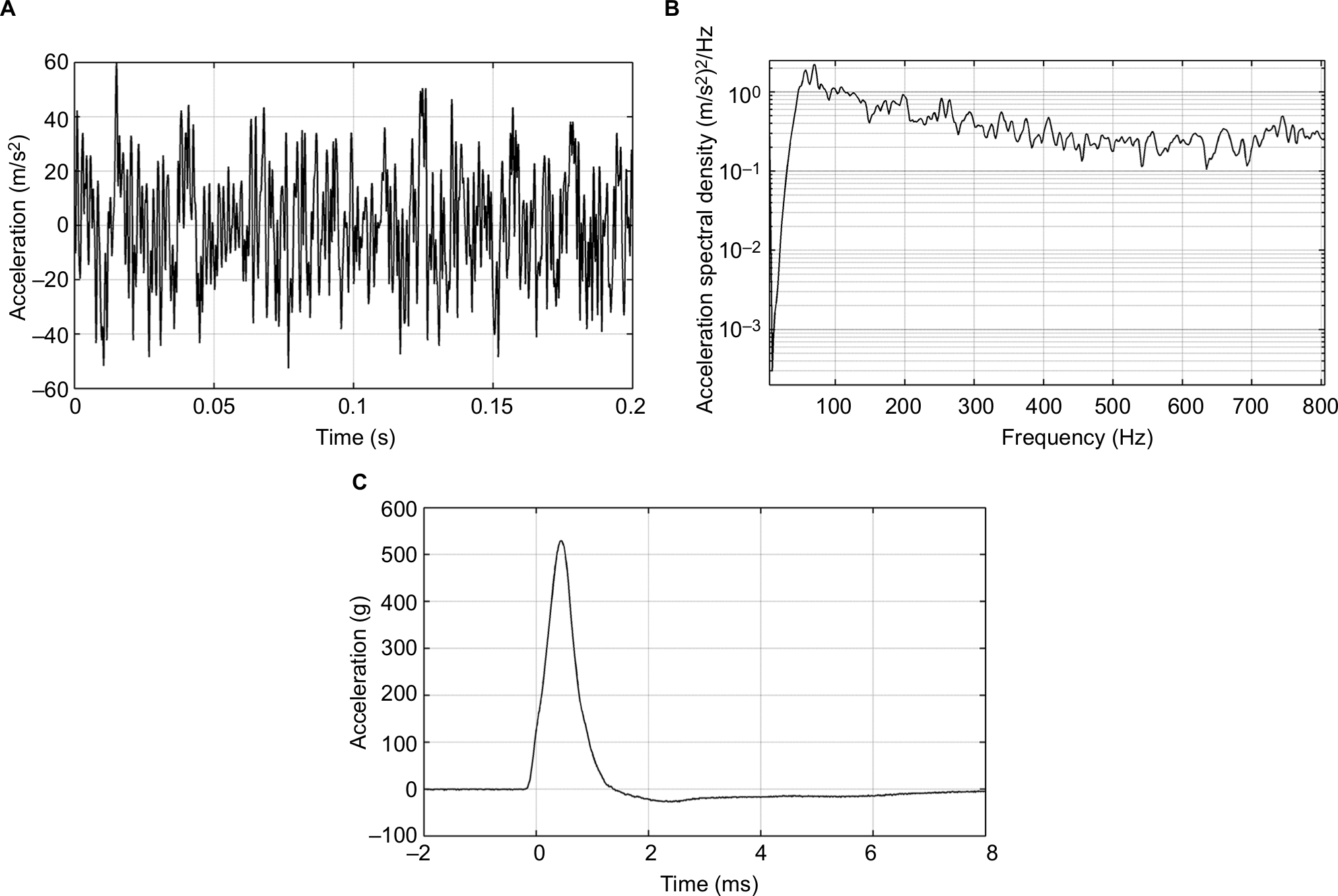 | Figure 3 Mechanical exposure of the random vibration and the shock test. Notes: (A) The time signal and (B) the acceleration spectral density of the same noise as applied in the random vibration test. (C) The average shape of the 500 g pulses over 1 ms that were applied to the five striking directions in the mechanical shock test. |
Lifetime estimation
To estimate the lifetime of the BCI implant, one sample is kept inside a chamber where it is continuously exposed to sound; as of February 2019, it had been tested for 45 months (Figure 4). Its functionality has been verified once a month by measuring its electro-acoustic performance. To include the effect of the body temperature under the skin, where the implant is positioned in patients, the ambient target temperature inside the chamber is 37±1°C, achieved by a heat-radiating light bulb. The temperature has been measured once a month and adjusted if needed. The sound source was chosen to be the Swedish radio channel program 1 comprising a mixture of both speech and music. This test is still running and will continue until the device fails.
 | Figure 4 The external view of the age-acceleration sound chamber used in the long-term sound exposure test of the implant. The chamber includes the bone conduction implant attached to the skull simulator, a speaker playing the Swedish radio channel P1 at 79.8 dBA, a microphone, a heat source, and a temperature sensor. |
The goal is that the BCI should function at least 10 years. To estimate the lifetime of the implant, the “use” can be accelerated by increasing the daily equivalent continuous sound level (LEQ), estimated to be 73.6 dBA by Neitzel et al,21 and increasing the daily time patients use the implant, assumed to be on average 12 hours, both at home and during work.18,19 Therefore, the average LEQ value in the box was increased from 73.6 to 78.6 dBA, and the exposure time from 12 to 24 hours continuously. These increases mean an approximately two times higher sound level (5 dB) than the normal sound exposure, which corresponds to 3.6 times increase in power or energy exposure, and a factor of 2 given by the increased exposure time from 12 to 24 hours. In total this means that the aging of the implant in the sound chamber is estimated to be accelerated by a total factor of ~7 times. The LEQ value and the temperature were measured once a month to ensure they maintained the desired values.
In comparison with the random vibration test, where the exposure to externally imposed vibration is evaluated, the long-term sound exposure test for lifetime estimation evaluates how the transducer is affected by its own vibrations.
MRI testing
A dipole electromagnet GMW 5403 (GMW Associates, Inc.) was used to investigate the effect on the transducer of a static magnetic field inside an MRI scanner (see the measurement setup in Figure 5A and B). The transducer was placed in a gap between two coils, where the dipole electromagnet generated a homogenous static magnetic field of 1.5 T. The static magnetically induced torque was measured at different angles (α) using a force gauge and an angle meter with the transducer mounted on a nonmagnetic rod that could freely rotate inside the field with low friction. In one test, the transducer was rotated 360 degrees, and the magnetically induced torque was measured every 10 degrees. In the other test, the transducer was kept in the magnetic field for 15 minutes at a position where α=0, similar to how it is positioned in a patient being examined in an MRI scanner.
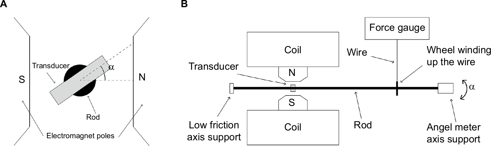 | Figure 5 Setup for magnetically induced torque measurements. Notes: (A) The mounting of the transducer inside the dipole electromagnet relative to the north and south poles where the magnetic field is uniform (1.5 T). (B) The transducer is fixed inside a cylindrical rod that can rotate with low friction, and a force gauge is connected to a disc on the rod to enable torque measurements. At one end an angle meter is positioned. |
Frequency response measurements
The electro-acoustic performance of the transducer was measured before and after all testing by using either an acoustic (Figure 6A) or an electric (Figure 6B) input. In the lifetime estimation experiment and the MRI tests, an acoustic frequency response was measured to detect possible damage to the implant. In the acoustic frequency response measurement, the complete BCI was excited by a speaker inside an anechoic test chamber, B&K 4222 (Brüel and Kjaer). Both the output force level and the THD were measured for frequencies between 100 and 10,000 Hz on a skull simulator using SoundCheck software (Varst Technology A/S, Højberg, Denmark) to control the measurement (Figure 6A).22 The input at the BCI AP microphone was kept at two constant SPLs of either 70 or 90 dB. At 70 dB SPL, the THD was measured, and at 90 dB SPL, the AP was saturated, thus giving the maximum power output (MPO) capacity of the BCI system not influenced by gain settings; at saturation THD is quite meaningless.
 | Figure 6 Setup for acoustic and electric measurements. Notes: (A) Electro-acoustic measurement setup for output force level and total harmonic distortion (THD) of the full bone conduction implant (BCI) system. The implant and audio processor are attached to the skull simulator inside the anechoic test chamber B&K 4222, where a speaker generates a constant sound pressure level from 100 to 10,000 Hz. A microphone connected to a power supply (mic power supply) and high pass filter amplifier (HPF & 20 dB gain) verifies the sound pressure level, and a laptop reads the output signal from the skull simulator. The measurement is monitored and controlled using SoundCheck software (Varst Technology) through a soundcard interface. (B) Setup for the electric frequency response measurements of the implant, from 100 to 10,000 Hz, using a skull simulator, an Agilent 35670A FFT Dynamic Signal Analyzer, and an Agilent 33220A Function/Arbitrary Waveform Generator (Agilent Technologies). The measurement was recorded using LabVIEW software via a universal serial bus (USB) interface. |
In the electric frequency response measurements for frequencies from 100 to 10,000 Hz, a constant input voltage was generated by an Agilent 33220A Function/Arbitrary Waveform Generator and controlled by an Agilent 35670A FFT Dynamic Signal Analyzer (Agilent Technologies Inc.). Data were collected using the software LabVIEW (National Instruments Corporation, Austin, TX, USA) via a universal serial bus interface. This measurement was done throughout the mechanical robustness and age-accelerated lifetime tests to compare with baseline data. The advantage with the electric frequency measurement is that the performance of the implant is measured without acoustical influence. If the AP fails over time, it can easily be replaced or have its audio settings adjusted, but replacing the implant requires surgery; the implant must therefore withstand higher demands.
Criteria
The criteria for maximum acceptable change in the electro-acoustic performance of a BCD could be based on either frequency response measurements, not affected by the settings in the AP, or the MPO when the AP is saturated. If the criteria are based on MPO measurements, compression and automatic functions should be disabled in the AP settings to avoid uncertainty if the maximum output was reached or not. The criteria can be specified in terms of maximum acceptable frequency shifting of the resonance peak(s) and/or loss in magnitude of the frequency response or in the MPO. Comparing the two measurement methods, MPO is a measurement of the whole system, that is, both the AP and the implant, while the frequency response excludes the AP and is a measurement of the implant alone. If the goal is to investigate only the implanted unit, the frequency response is the more reliable measurement. This measurement technique is especially important for long-term measurements, such as the age-accelerated test, because the AP can always be replaced if it fails to function. In other words, if a change is observed in the MPO curve, it is possible to know if the change is related to the condition of the AP or the implant by also measuring the frequency response.
The general goal of the performance acceptance criteria is to make sure that the device offers sufficient hearing rehabilitation for indicated patients and that any change in the electro-acoustic performance due to mechanical exposure is negligible or can be adjusted for in the AP settings without reaching saturation or generating too much distortion. Yet no standardized test methods are developed for active transcutaneous BCDs to investigate the mechanical robustness and specific requirements to withstand. Instead, manufacturers use their own standards to assure proper function for intended use. The stress levels used in these tests are meant to be representative for all active transcutaneous BCDs and based on assumed maximum exposure levels; that is, they are not excessively high or unrealistically low. As long as realistic maximum exposure levels are applied during the tests, the manufacturers can formulate and motivate their criteria for maximum acceptable change in performance of the implant.
We recommend formulating the criteria to meet the output requirements of a fully functioning device based on objective measurable parameters, such as frequency response measurements. In a study by Taghavi et al,10 the frequency response of the BCI was specified to have a low-frequency resonance peak around 800 Hz (640–960 Hz) and a high resonance peak around 4,500 Hz (3,600–5,400 Hz). In terms of production variability, a maximum acceptable deviation in the frequency response is set to ±20% for the resonance frequency peaks and a 5 dB loss in the magnitude at the middle frequencies, around 2 kHz. Therefore, the same criteria as for maximum acceptable production variability is used as criteria for mechanical robustness for the BCI in this study.
Results
Mechanical testing
There was no observed effect on the transducer frequency response after the random vibration test and mechanical shock test in comparison with the baseline measurement (Figure 7A and B, respectively).
 | Figure 7 The frequency response with electric input of 1 Vpeak to the transducer before (solid line) and after (dashed line) (A) the random vibration test, (B) the mechanical shock test, (C) the pendulum test, and (D) the 2.5 J impact test. |
In the pendulum test, the transducer was struck in five orthogonal directions from a height of 50 cm, which resulted in a change of the frequency response. The low-frequency resonance peak shifted from 832 to 724 Hz (13%) and decreased 1.1 dB in amplitude, and the high-frequency peak shifted from 5,492 to 5,012 Hz (9%) and decreased 4.1 dB (Figure 7C). Each direction was tested in ascending order from direction 1 to 5 (Figure 2A), and small increments were observed after each direction, but it was not until the fourth striking direction that the maximum change was reached.
The impact test of 2.5 J did not have any negative effect on the low-frequency resonance peak, while the high-frequency peak increased 2.1 dB in amplitude and shifted from 5,012 to 4,571 Hz (9%; Figure 7D).
Lifetime estimation
The average value of the monthly measured temperature and LEQ-value in the test chamber were 37.8±0.8°C and 78.6±4.5 dBA, respectively. Figure 8A shows the frequency responses of the transducer after the age-accelerating test in comparison with baseline measurement at the start, verifying a stable and unaffected implant performance over time. The transducer and AP combined were also verified to function normally after the age-accelerating test, by measurements of the MPO at 90 dB SPL and THD at 70 dB SPL (Figure 8B).
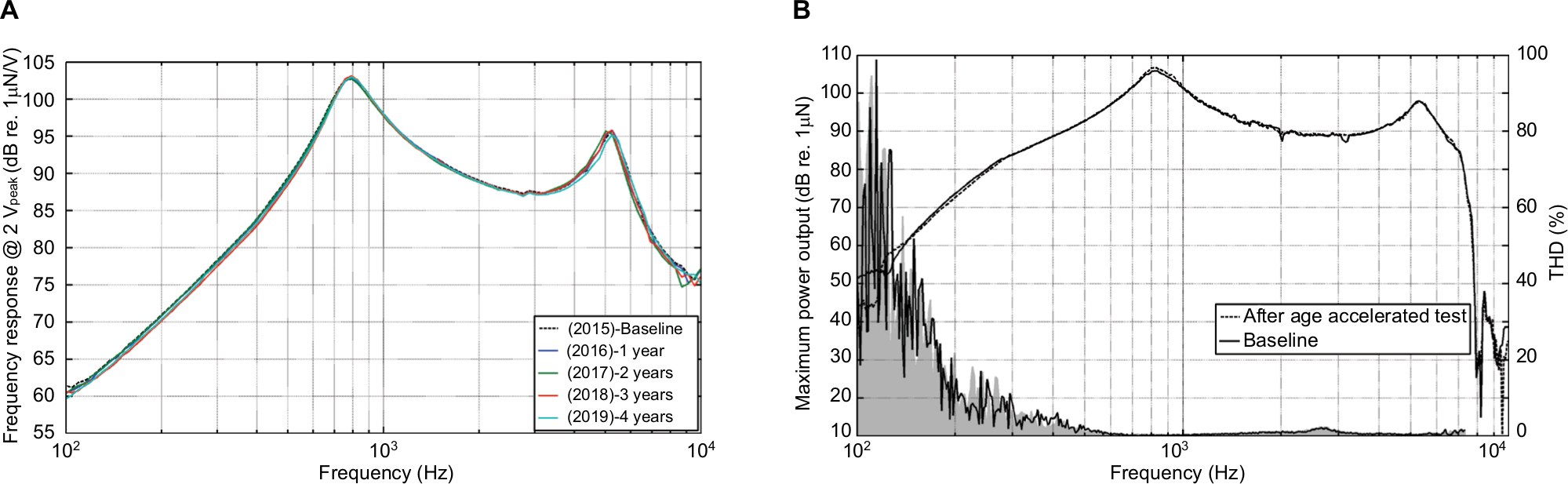 | Figure 8 Performance after the age-accelerated test. Notes: (A) Frequency response of the transducer at baseline (dashed line) and for 3 years (solid lines) in the age-accelerated test, and (B) maximum power output (MPO) at 90 dB sound pressure level (SPL) of the transducer at baseline (dashed line) after the age-accelerated test (solid line), and total harmonic distortion (THD) at 70 dB SPL (gray area) in comparison with baseline (solid line). |
At the time of writing (February 2019), the implant had been operating inside the age-accelerating test chamber without any significant change in performance for over 45 months. With an accelerated aging factor of seven times, these 45 months correspond to a 26-year period of usage for patients who are using the device for 12 hours on a daily basis. In other words, this BCI is estimated to have an expected lifetime of >26 years.
MRI testing
The magnetically induced torque acting on the BCI transducer followed a sinusoidal function with a maximum amplitude of 0.135 Nm as seen in Figure 9A. A ±90 degree angle shift occurred every 90 degrees due to the interaction between the applied magnetic field and the induced magnetic field in the soft iron material of the transducer. Therefore, the torque first had to be measured counterclockwise and then clockwise, or vice versa, in order to measure one full lap from 0 to 360 degrees, as shown in Figure 9A.
 | Figure 9 Results from the MRI testing. Notes: (A) The magnetically induced torque of the transducer when it was rotated 360 degrees inside the static magnetic field of the dipole electromagnet. (B) Maximum power output (MPO) at 90 dB sound pressure level (SPL) of the transducer at baseline (dashed line) and after the magnetic resonance imaging (MRI) test (solid line), and total harmonic distortion (THD) at 70 dB SPL (gray area) in comparison with baseline (solid line). |
When the transducer was exposed to the static magnetic field of 1.5 T for 15 minutes, both the MPO at 90 dB SPL and THD at 70 dB SPL were unaffected (Figure 9B).
Discussion
A series of tests to evaluate robustness has been developed and used on the BCI system. These tests may also be applied to other active transcutaneous BCD. However, relevant criteria of maximum acceptable change in electro-acoustic performance need to be determined for each individual type of device, which was not addressed in this study. For example, these tests do not apply for the transducers in BAHA processors, which are worn externally and therefore expose higher risks to mechanical trauma. On the other hand, if a BAHA processor is damaged, it can easily be replaced without surgery.
The mechanical tests were performed in a certain order, with the random vibration test first, followed by the shock test, as these two tests were assumed to be the least harmful. These tests had no observed effect on the electro-acoustic performance and was followed by the pendulum test to simulate a drop from 50 cm onto a stiff metallic surface. The pendulum test caused a more noticeable effect on transducer performance even though the frequency response remained within the criteria. This change was considered minor and can easily be compensated for by increasing the gain in the AP settings without reaching saturation or generating high distortion. Regarding the relevance of the pendulum test, if an unsealed implant was accidently dropped on the floor before or during surgery, it would be contaminated and should not be implanted. However, if the unsealed implant was accidentally dropped on a sterilized table or roughly handled, it could still be implanted. The pendulum test is therefore limited to 50 cm and should assure that the implant is designed to withstand the scenario of being dropped on a sterile table, typically made of metal where draping of the table is not accounted for. In comparison with the mechanical shock test, the pendulum test is almost identical, except that the pendulum test exerts a faster and larger pulse and is therefore considered much more severe than the mechanical shock test. Therefore, if the implant withstands the pendulum test, there is no need to perform the mechanical shock test.
Once in place, the implant is no longer at risk of being dropped, but it can still be exposed to external impacts and smaller shocks, and it needs to withstand vibrations, both externally imposed and internally generated by the transducer itself during normal use. To test the ability of transducers to withstand external impacts, the mechanical impact test was performed. Remarkably, no major effect was observed in electro-acoustic performance even though the same transducer had been used in the sequence of all mechanical tests.
The age-accelerating test tested the implant for approximately two times longer and at four times higher sound power (~5 dB higher amplitude level) than a BCI in normal use. These conditions give an estimated accelerated aging factor of 7; thus at present, after 45 months of testing, the estimated lifetime of an implant is at least 26 years of normal use. This estimation is based on one sample BCI that was picked from the backup implants remaining after implantation surgery in all 16 patients in the clinical study. All these implants were very similar, had passed all quality assurance tests, and were approved for implantation. The test implant was picked at random. Patients’ lifestyle may be another factor that can affect the lifetime of the implants other than long periods of sound exposure, body temperature, and high sound levels. This effect is difficult to include in the age-accelerating test, since it varies among individuals and is hard to predict, but as the device has passed through all mechanical tests, it should resist such exposures with safe margins.
Because the patient might need an MRI, the implant’s robustness related to MRI must be evaluated as well. From previous studies about the MRI safety of the BCI implant, the magnetically induced torque caused by the retention magnet in the receiver coil is ~0.40 Nm during 1.5 T MRI.31 In comparison with the maximum induced torque on the transducer, which is 0.135 Nm, the retention magnet is concluded to be the main contributor to magnetically induced torque. The observed effects on the electro-acoustic performance are in line with the findings in Fredén Jansson et al,26 where the BCI was scanned in a 1.5 T MRI scanner. However, the torque of the retention magnet and that of the transducer are not assumed to constructively interact as their magnetization directions in relation to the static magnetic field of the MRI scanner are different. For this reason, the torques of the transducer and retention magnet cannot simply be added to determine the total torque of the whole implant in a worst case scenario. This study found that the peak torque on the transducer occurred at a deflection angle perpendicular to the peak torque from the retention magnet, which means that the torque of the transducer is zero when the torque of the retention magnet is maximum and vice versa. This indicates that the worst case scenario torque of the whole implant equals the maximum torque on the retention magnet, because it is higher than the maximum torque of the transducer. Even if the BCI passed these pilot tests of 1.5 T MRI, additional tests are needed for the device to be approved for MRI in a patient. Also, it is common to use MRI scanners with higher static magnetic field strengths, such as 3 T. This will have a significantly stronger impact on an implanted unit than 1.5T, which need to be tested in a separate study. Among all tests in this study, the ones relevant for evaluating the postsurgical robustness of the implant are the MRI test, mechanical shock test, random vibration, and long-term sound exposure, while the pendulum test is more relevant for the presurgical robustness.
Regarding the non-accelerated usage time in actual patients, it has been ~6 years since the first patient received a BCI implant. Based on the measurement of patient-related outcomes and audiometric results, no implant deterioration has been observed in that patient and none of the 16 patients, who to date have an accumulated usage time of 58 years, have reported serious adverse events.
Conclusion
The BCI was tested using a series of mechanical tests comprising a random vibration test, a shock test, a pendulum test, and an impact test. In addition, MRI compatibility of the BCI was tested in a static magnetic field of 1.5 T under normal scanning conditions. Finally, the lifetime of one implant was estimated under accelerated aging conditions.
The criteria proposed for the BCI to be considered fully functional are as follows: 1) the change in resonance peaks should not be >±20% in frequency, and 2) the magnitude should not deteriorate >5 dB for the middle frequencies, typically measured around 2 kHz.
The BCI withstood the static magnetic field of 1.5 T, fulfilled the robustness criteria in all mechanical tests, and had a lifetime estimated to be >26 years for patients using the device for 12 hours on a daily basis.
The same testing can be applied to evaluate other similar active transcutaneous BCDs designed with the transducer directly attached to the skull bone under intact skin and provided that appropriate criteria are set for the specific device.
Acknowledgments
The authors would like to thank R Dumas for his contribution of laboratory access and support. Also great thanks to master’s thesis student HJ Harðardóttir for her laboratory support.
Disclosure
The authors Bo Håkansson, Sabine Reinfeldt, and Måns Eeg-Olofsson have been part-time consultants for Oticon Medical during the clinical study of the BCI. The authors report no other conflicts of interest in this work.
References
Oticon. Industry symposia: Oticon Medical at the Osseo 2015. 5th International Congress on Bone Conduction Hearing and Related Technologies. May 20–23, 2015. Lake Louise, Canada. | ||
Håkansson B, Tjellström A, Rosenhall U, Carlsson P. The bone-anchored hearing aid. Principal design and a psychoacoustical evaluation. Acta Otolaryngol. 1985;100(3-4):229–239. | ||
Reinfeldt S, Håkansson B, Taghavi H, Eeg-Olofsson M. New developments in bone-conduction hearing implants: a review. Med Devices (Auckl). 2015;8:79–93. | ||
Tjellström A, Granström G. Long-term follow-up with the bone-anchored hearing aid: a review of the first 100 patients between 1977 and 1985. Ear Nose Throat J. 1994;73(2):112–114. | ||
Asma A, Ubaidah MA, Hasan SS, et al. Surgical outcome of bone anchored hearing aid (Baha) implant surgery: a 10 years experience. Indian J Otolaryngol Head Neck Surg. 2013;65(3):251–254. | ||
Tjellström A, Håkansson B, Granström G. Bone-anchored hearing aids: current status in adults and children. Otolaryngol Clin North Am. 2001;34(2):337–364. | ||
Snik FM, Mylanus EAM, Proops DW, et al. Consensus statements on the Baha system: where do we stand at present? Ann Otol Rhinol Laryngol. 2005;114(12_suppl):2–12. | ||
Dun CA, Faber HT, de Wolf MJ, Mylanus EA, Cremers CW, Hol MK. Assessment of more than 1,000 implanted percutaneous bone conduction devices: skin reactions and implant survival. Otol Neurotol. 2012;33(2):192–198. | ||
Kiringoda R, Lustig LR. A meta-analysis of the complications associated with osseointegrated hearing aids. Otol Neurotol. 2013;34(5):790–794. | ||
Taghavi H, Håkansson B, Reinfeldt S, et al. Technical design of a new bone conduction implant (BCI) system. Int J Audiol. 2015;54(10):736–744. | ||
Håkansson B, Eeg-Olofsson M, Reinfeldt S, Stenfelt S, Granström G. Percutaneous versus transcutaneous bone conduction implant system: a feasibility study on a cadaver head. Oto Neuro. 2008;29:1132–1139. | ||
Eeg-Olofsson M, Stenfelt S, Håkansson B, et al. Optimal position of a new bone conduction implant. Cochlear Implants Int. 2011;12(Suppl1):S136–S138. | ||
Taghavi H, Håkansson B, Reinfeldt S, Eeg-Olofsson M, Akhshijan S. Feedback analysis in percutaneous bone-conduction device and bone-conduction implant on a dry cranium. Otol Neurotol. 2012;33(3):413–420. | ||
Eeg-Olofsson M, Håkansson B, Reinfeldt S, et al. The bone conduction implant--first implantation, surgical and audiologic aspects. Otol Neurotol. 2014;35(4):679–685. | ||
Reinfeldt S, Håkansson B, Taghavi H, Fredén Jansson KJ, Eeg-Olofsson M. The bone conduction implant: clinical results of the first six patients. Int J Audiol. 2015;54(6):408–416. | ||
Rigato C, Reinfeldt S, Håkansson B, Jansson KJ, Hol MK, Eeg-Olofsson M. Audiometric comparison between the first patients with the transcutaneous bone conduction implant and matched percutaneous bone anchored hearing device users. Otol Neurotol. 2016;37(9):1381–1387. | ||
Taghavi H, Håkansson B, Reinfeldt S. Analysis and design of RF power and data link using amplitude modulation of Class-E for a novel bone conduction implant. IEEE Trans Biomed Eng. 2012;59(11):3050–3059. | ||
Dutt SN, McDermott AL, Jelbert A, Reid AP, Proops DW. Day to day use and service-related issues with the bone-anchored hearing aid: the Entific Medical Systems questionnaire. J Laryngol Otol Suppl. 2002;116(S28):20–28. | ||
Sánchez-Camón I, Lassaletta L, Castro A, Gavilán J. Quality of life of patients with BAHA. Acta Otorrinolaringol Esp. 2007;58(7):316–320. | ||
Flamme GA, Stephenson MR, Deiters K, et al. Typical noise exposure in daily life. Int J Audiol. 2012;51(sup1):S3–S11. | ||
Neitzel RL, Svensson EB, Sayler SK, Ann-Christin J. A comparison of occupational and nonoccupational noise exposures in Sweden. Noise Health. 2014;16(72):270–278. | ||
Håkansson B, Carlsson P. Skull simulator for direct bone conduction hearing devices. Scand Audiol. 1989;18(2):91–98. | ||
Battmer RD, Linz B, Lenarz T. A review of device failure in more than 23 years of clinical experience of a cochlear implant program with more than 3,400 implantees. Otol Neurotol. 2009;30(4):455–463. | ||
Association for the Advancement of Medical Instrumentation. Cochlear implant systems: Requirements for safety, functional verification, labeling and reliability reporting. ANSI/AAMI CI86:2017. | ||
Kim BG, Kim JW, Park JJ, Kim SH, Kim HN, Choi JY. Adverse events and discomfort during magnetic resonance imaging in cochlear implant recipients. JAMA Otolaryngol Head Neck Surg. 2015;141(1):45–52. | ||
Fredén Jansson KJ, Håkansson B, Reinfeldt S, Rigato C, Eeg-Olofsson M. Magnetic resonance imaging investigation of the bone conduction implant – a pilot study at 1.5 Tesla. Med Devices (Auckl). 2016;8:413–423. | ||
Jansson KJ, Håkansson B, Reinfeldt S, Taghavi H, Eeg-Olofsson M. MRI induced torque and demagnetization in retention magnets for a bone conduction implant. IEEE Trans Biomed Eng. 2014;61(6):1887–1893. | ||
Håkansson BE. The balanced electromagnetic separation transducer a new bone conduction transducer. J Acoust Soc Am. 2003;113(2):818–825. | ||
Jansson KJF, Håkansson B, Johannsen L, Tengstrand T. Electro-acoustic performance of the new bone vibrator Radioear B81: a comparison with the conventional Radioear B71. Int J Audio. 2015;54(5):334–340. | ||
Raine CH, Lee CA, Strachan DR, Totten CT, Khan S. Skin flap thickness in cochlear implant patients – a prospective study. Cochlear Implants Int. 2007;8(3):148–157. | ||
Fredén Jansson KJ. The balanced electromagnetic separation transducer for bone conduction audiometry and hearing REHabilitation. Doctoral thesis. Department of Electrical Engineering, Chalmers University of Technology. |
 © 2019 The Author(s). This work is published and licensed by Dove Medical Press Limited. The
full terms of this license are available at https://www.dovepress.com/terms
and incorporate the Creative Commons Attribution
- Non Commercial (unported, 3.0) License.
By accessing the work you hereby accept the Terms. Non-commercial uses of the work are permitted
without any further permission from Dove Medical Press Limited, provided the work is properly
attributed. For permission for commercial use of this work, please see paragraphs 4.2 and 5 of our Terms.
© 2019 The Author(s). This work is published and licensed by Dove Medical Press Limited. The
full terms of this license are available at https://www.dovepress.com/terms
and incorporate the Creative Commons Attribution
- Non Commercial (unported, 3.0) License.
By accessing the work you hereby accept the Terms. Non-commercial uses of the work are permitted
without any further permission from Dove Medical Press Limited, provided the work is properly
attributed. For permission for commercial use of this work, please see paragraphs 4.2 and 5 of our Terms.