Back to Journals » Medical Devices: Evidence and Research » Volume 18
Non-Invasive Laser Surgery With Deep Operating Depth Using Multibeam Interference
Authors Liu J ![]()
Received 31 October 2024
Accepted for publication 22 January 2025
Published 15 February 2025 Volume 2025:18 Pages 123—136
DOI https://doi.org/10.2147/MDER.S498706
Checked for plagiarism Yes
Review by Single anonymous peer review
Peer reviewer comments 2
Editor who approved publication: Dr Scott Fraser
Video abstract presented by Liu.
Views: 176
Joyce Liu
School of Medicine and Dentistry, University of Rochester Medical Center, Rochester, NY, 14642, USA
Correspondence: Joyce Liu, School of Medicine and Dentistry, University of Rochester Medical Center, 601 Elmwood Ave, Rochester, NY, 14642, USA, Email [email protected]
Purpose: Laser surgery can use photo-chemical, photo-thermal, photo-ablative, and photo-mechanical effects to treat various tissues in the human body, and has unique advantages of extremely high precision, non-invasive penetration, and fast operation speed. However, at present, the effective penetration depth of directly illuminating light in the body is only several millimeters. Therefore, increasing the safe operating depth for non-invasive laser surgery will have important, widespread, and irreplaceable applications in the future.
Methods: The method is based on improving a recently emerged technique. Its principle involves using a negative dispersion device to broaden the width of the short light pulse first. Then, after the pulse enters the body, as its peak intensity is reduced, the skin and healthy tissues in the laser propagation path cannot be injured. Meanwhile, since body tissues have positive dispersion, the broadened width of the laser pulse will be shortened back. When the broadened pulse is completely shortened, a thin inner light layer with high intensity will be formed in the body and used as a scalpel to treat target tissue.
Results: The theoretical calculation results have shown that the designed apparatus has excellent performance. Its safe non-invasive operating depth can be more than 70 millimeters with the possibility of up to 130 millimeters. Surgery precisions are around 1 micron transversely and about 1 millimeter longitudinally in theory.
Conclusion: An improved method of non-invasive laser surgery with deep operation depth has been investigated theoretically. The calculations show that the designed apparatus has excellent performance. The proposed method depends on two well-known physical phenomena: light pulse broadening and shortening caused by optical negative and positive dispersions, and thus has solid basis. The developed method will have important, widespread and irreplaceable applications in the medical surgery field.
Keywords: absorption, scattering, negative dispersion fiber, penetration depth
Introduction
As a special type of surgery, laser surgery uses photo-chemical, photo-thermal, photo-ablative, and photo-mechanical effects to irradiate, coagulate, ablate, and even vaporize various tissues in the human body,1,2 such as using irradiation to enhance medicinal effects to desired tissues, using coagulation to control bleeding, using ablation to cut cancerous tumors, using thermal expansion to shatter intraluminal stones, and even using vaporization to eliminate harmful deposits in the trachea, esophagus, intestine, stomach, and blood vessels.
One unusual advantage of laser surgery is the penetration ability of light, which makes some laser therapies non-incisional, such as those used in photodynamic therapy.3 In these cases, the laser light can penetrate the layers of skin to heat tissues underneath, such as tissue containing chromophore, which absorbs light more effectively and so can be treated by the penetrated light.
However, body tissues absorb and scatter light strongly, which not only attenuates the light energy rapidly, but also produces heavy random scattered light to disturb the laser treatment and flood the signal light if imaging the target is needed for imaging-guided surgery. For example, when a 1 milliwatts light beam with wavelength  millimeters travels a distance of 100 millimeters in the human body (namely, the forearm), under the dual actions of absorption and scattering, the beam intensity will drop to below
  milliwatts.4 Such a low intensity cannot induce any effect on body tissues. At present, the effective penetration depth of directly illuminating light in the body is only several millimeters,3 which is too shallow for laser surgery.
Scattered light may go somewhat deeper, such as to 50 millimeters. However, random scattered light is useless and even harmful for controlling the laser treatment and surgery. The safe treatment or operating depth also cannot be increased by raising the incident intensity, otherwise the layers of skin and other tissues in the laser beam traveling path will be injured.
Laser surgery also has another unique advantage of extremely high precision, which is up to the laser light wavelength of around 1 micron. This characteristic makes laser surgery able to do operations accurately, and so is useful for fine or risky operations at locations such as near important nerves or vessels.
Therefore, non-invasive laser surgery having significantly increased safe operating depths will have important, widespread and irreplaceable applications in the medical surgery field, while also considering the other advantages of less infection and fast operation time. Non-invasive laser surgery will make a huge contribution to millions of patients in the future.
The desired non-invasive laser surgery is possible to be realized by utilizing multibeam interference. Its principle was reported at an international conference recently.5 However, in the initially reported work, there are two problems. First, the negative dispersion device is made of two optical prisms. Therefore, the required change rate of the negative dispersion, which must be the exact reverse of the positive dispersion of human tissue, is difficult to be realized because the output surface shape of one prism needs to be nonlinear.5 Second, the values of the achievable safe operating depths are calculated as estimates. Specifically, the absorption and scattering coefficients of the human body were modified by attenuation factor  inappropriately. This results in the calculated results not having a solid basis and being inaccurate.
In this paper, the negative dispersion device is made of negative dispersion fiber and the calculations of achievable safe operating depths are improved. With advances of optical fiber development, current negative dispersion fibers may produce various negative dispersions including the expected mirrored negative dispersion to match human tissues. The optical fiber also has small volume and light weight.
In addition, the new calculations are based on the analysis for the beam intensity change of the multibeam interference in the human body, and so the obtained results are accurate and reliable. These new results show that the achievable safe operating depth in the human body can be over 70 millimeters with good possibility to reach 130 millimeters. The desired laser surgery will have high operation precisions of around 1 micron in the lateral direction, and about 1 millimeter in the depth direction. Considering the thickest depth of the common human body is about 25 centimeters to 30 centimeters at the chest, if the maximum safe operating depth is near 150 millimeters, the hope of being able to treat the whole body will be realized (from two sides of the body, respectively).
Method
Almost all optical media in nature have positive dispersions, including human body tissues.6 Optical dispersions can change light pulse width. On the top of Figure 1, a short light pulse comes from a mode-locked laser and enters a positive dispersion medium. In the medium, the different frequency components of the pulse, that is, the multiple light beams constituting the pulse, travel at different speeds. To describe the pulse width change visually, the solid line, dashed line and dotted line represent three planar wavefronts of the beams corresponding to three different angular frequencies  ,
,  and
and  If
If  the wavefront represented by the solid line travels fastest, that is, the higher the beam frequency is, the slower the beam travels in the positive dispersion medium. Thus, because the phase differences between any two frequency adjacent beams of the multiple beams become larger and larger, the pulse width broadens, which makes the composite intensity of the multiple beams gradually become weaker and weaker. This pulse-broadening process is caused by multibeam destructive interference, which is a typical optical interference phenomenon, and its cause has been explained by many optics books.7 Note that, for a short light pulse, when it has just exited from a mode-locked laser, the phase differences between any two frequency adjacent beams are equal to zero.
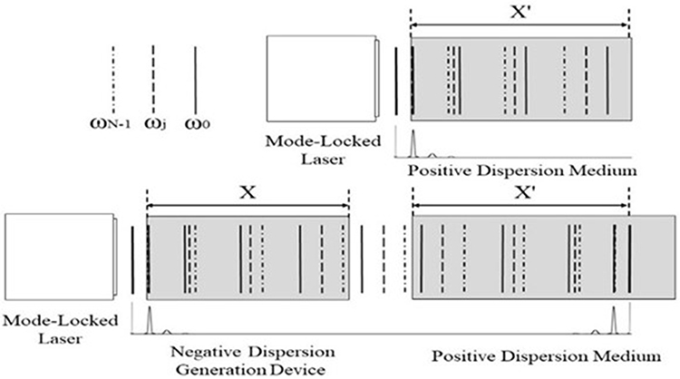 |
Figure 1 Light pulse width broadening and shortening in optical media caused by opposite dispersions. |
When the multiple beams travel in a negative dispersion medium, such as a man-made negative dispersion generation device, their traveling speeds are reversed, that is, the higher the beam frequency is, the faster the beam travels. In the bottom left of Figure 1, a short light pulse comes from a mode-locked laser, and enters a negative dispersion generation device first. Since  in the negative dispersion generation device, the wavefront presented by the dotted line travels fastest. Although the speeds of the three wavefronts are reversed, because the phase differences of the multiple beams gradually become larger and larger too, the pulse width will broaden, and the composite intensity of the multiple beams becomes weaker and weaker in the negative dispersion generation device.
Therefore, no matter whether the medium dispersion is positive or negative, as long as the dispersion increases the phase differences of the multiple beams to become larger and larger, pulse broadening will happen. Otherwise, pulse shortening will happen.
Such a pulse-shortening process is shown in the bottom right of Figure 1. After leaving the negative dispersion generation device, the width-broadened light pulse with expanded phase differences enters a positive dispersion medium. This time, in the positive dispersion medium, the wavefront represented by the solid line travels fastest since  . Thus, the expanded phase differences of the multiple beams now gradually become smaller and smaller in the positive dispersion medium, which shortens the pulse width.
If the negative dispersion generation device can produce a dispersion which equals that produced by the positive dispersion medium accurately and reversely, that is, the negative dispersion generation device can produce a mirrored dispersion, a short light pulse will reappear in the positive dispersion medium at the end and have its initial width. In other words, a composite light intensity maximum of the multiple beams, that is, an inner light layer with high intensity, will be formed by multibeam constructive interference in the positive dispersion turbid medium. This pulse-shortening process caused by multibeam constructive interference is a typical optical interference phenomenon too, and its cause has also been explained by many optics books.7
If the thickness of the formed light layer is thin, in the majority of the path that the laser beam travels in the positive dispersion turbid medium, the composite intensity of the multiple beams is low. Light absorption and scattering are directly proportional to the light intensity.8 Thus, the light absorption and scattering in the majority of the path that the laser beam travels in the turbid medium may be reduced.
The thickness of the formed inner light layer can be very thin and the composite intensity of the multiple beams in the traveling path can be very low if the beam number  of the multiple beams is large (see calculations below). In addition, if the number
  is large, the intensity of the formed inner light layer can be very high.
The method to first broaden and then shorten the light pulse width is similar to the ideal method that involves making the laser beams disappear in the light traveling path to eliminate the light absorption and scattering of the optical turbid medium, and only appear on the desired location to illuminate the target in the medium.
The light pulse broadening and shortening by opposite optical dispersions are two well-known physical phenomena.9 Therefore, the feasibility of using the investigated method to reduce the light absorption and scattering has a solid basis.
Design of the Apparatus
Figure 2 shows the optical structure of the non-invasive laser surgery apparatus designed based on the investigated method. In Figure 2, a mode-locked fiber laser is pumped by several light-emitting diodes with different emitting frequencies for producing laser pulses having a wide spectral range. The fiber laser can decrease apparatus volume and weight for convenience. The pump light enters a doped fiber through a coupling element WDM. An optical isolator and a polarization controller are used to ensure unidirectional beam oscillation.
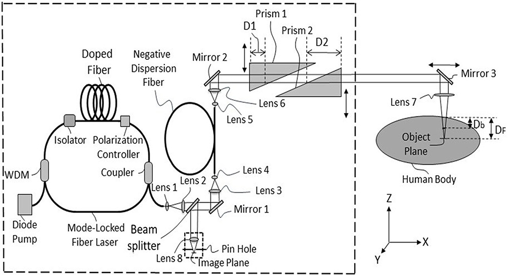 |
Figure 2 Optical structure diagram of the non-invasive laser surgery apparatus. |
After the laser pulse, that is, the multiple beams exit through an optical coupler, the beam diameters are enlarged by lens 1 and lens 2. Because the multiple beams come from a mode-locked laser, their angular frequencies  are different but with equal angular frequency intervals
  ,10 that is,

where  is the number of the beams, and
  is the lowest angular frequency of the
  beams. We suppose these beams are polarized by a polarizer and so they have the same polarization directions.
When these beams propagate along the  direction, since these beams are superimposed to each other, their composite field is
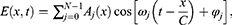
where  and
and  are the amplitude and initial phase of the
  th beam at
  and
and  .
.  is the time.
  is the speed of light in a vacuum.
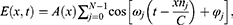
By making dispersion compensation to laser cavity gain using dye,11 the amplitudes  can be modified to become the same. Thus,
  no longer changes with
  Then, when these beams enter an optical medium, since the propagation speed of the
  th beam changes from C to
  where
where  is the refractive index of the medium corresponding to the angular frequency
  Eq. (2) becomes
defining  as the phase difference between two beams corresponding to angular frequencies
  and
and  then
then

When  the
the  beams will interfere with each other constructively, such multibeam constructive interference will create a composite intensity maximum, that is, create a strong light pulse.
Therefore, when the laser beams are just emitted out from the mode-locked laser, they constitute an ultra-short light pulse because their phase differences are all zero and the number  is large. After passing through the beam splitter, 10% of the light energy is reflected by mirror 1 and enters the two lenses 3 and 4 for beam diameter shrinking. Usage of the beam splitter with low transmittance is for less signal light energy loss when the signal light is later reflected by the beam splitter, which is for imaging the target if the laser surgery needs imaging guidance. Then, the
  beams enter a negative dispersion generation device consisting of a fiber.
Current negative dispersion fibers are able to produce negative dispersions with different change rates. There are various micro-structures built in the optical fibers to produce negative dispersions, such as air-core Bragg gratings, square-lattice, dual-core, modal interaction, etc.12–15 Therefore, the fiber device may produce the ideal dispersion, especially, the mirrored negative dispersion to match the corresponding turbid medium. Current optical fiber devices also have fewer components, small volumes and light weights.
For ideally compensating the positive dispersion generated in the turbid medium, all optical path differences produced by all pairs of two frequency adjacent beams in the turbid medium must be generated in the negative dispersion fiber equally and with the opposite signs, that is, a mirrored negative dispersion must be generated.
When the beams travel a distance  in the negative dispersion fiber, two beams corresponding to the angular frequencies
  and
and  will produce an optical path difference
  as
as


and  and
and  are the equivalent refractive indexes of the negative dispersion fiber corresponding to the angular frequencies
  and
and  . Here, the equivalent refractive index is defined as the refractive index of a man-made optical material (such as a negative dispersion generation fiber).
Suppose the optical path difference produced by two beams corresponding to the angular frequencies  and
and  in the turbid medium is


and  and
and  are the refractive indexes of the turbid medium corresponding to the angular frequencies
  and
and 
 is the traveling distance of the beams in the turbid medium (
 may be regarded as the operating depth in the body).
In order to generate mirrored negative dispersion, the negative dispersion generation device needs to generate the following optical path differences

Eq. (9) gives the negative optical path difference  required for two beams corresponding to the angular frequencies
  and
and  in the negative dispersion fiber.
The design of the negative dispersion fiber may start with measuring the turbid medium refractive indexes  corresponding to different frequencies
  within the required range first. Because the number of the frequencies is large, only partial and discrete data need to be measured. Then, one can use a computer to fit the refractive index change curve with respect to frequency from the obtained data. There are several dispersion equations for fitting the refractive index change curves, such as Cauchy, Hartmann, Conrady and Kettler-Drude equations, etc.16
Then,  ,
,  and
and  can be obtained from the fitted refractive index curve of the turbid medium. And then, according to the required processing distance
  , the required negative dispersion change rate of the negative dispersion fiber, that is, the required equivalent refractive indexes
  and
and  , and
, and  may be calculated, which also depend on the chosen value of the length
  of the negative dispersion fiber by Eq. (9). The value
  is variable, which is convenient for determining
  ,
,  and
and  .
.
Except for the negative dispersion fiber, other optical components used in the apparatus will produce positive dispersions. If the total value of the traveling path lengths of the beams in these components is much less than  these additional positive dispersions can be ignored. Otherwise, they also need to be compensated. For simplifying the apparatus manufacturing, and also for simplifying the calculations here, all of the optical components in the apparatus are ideally made of material having the same or approximately the same dispersion property as that of the corresponding turbid medium for the best results. To satisfy such a requirement has become relatively easy in recent years. For example, finding a material whose optical property is approximate to body tissue is not difficult because of the development of tissue-simulating phantoms.17 In the optical spectroscopy, imaging, and therapy research fields, such simulating materials have been widely used. The dispersion, absorption and scattering properties of these materials are characteristic of human body tissues.
The diameters of the  light beams from the negative dispersion fiber are expanded by the lenses 5 and 6. After being reflected by mirror 2, these beams become parallel beams and enter the operating depth adjuster consisting of two triangular prisms 1 and 2.
The length and dispersion change rate of the negative dispersion fiber are fixed, which determines a fixed operating depth  in the turbid medium by Eq. (9), and so every apparatus has a fixed operating depth
Therefore, if the expected operating depth in the body is  the depth changes by adjusting two prisms 1 and 2 are
  and
and  then by making
the expected operating depth  can be adjusted by changing
  Note that the two prisms 1 and 2 should be made from the same material as the turbid medium or have the same or approximately the same dispersion rate as the turbid medium. Because two triangular prisms have symmetrical shapes, no unwanted dispersions will be produced by this operating depth adjuster.
Then, the  parallel beams enter the human body by reflection by mirror 3. An inner light layer will be created with the depth of
When using lens 7, the focal point of lens 7 is at the position with the depth of  . The formed inner light layer and the focal point of lens 7 locate at different positions. It provides the benefit of conveniently controlling the operating area size and operating intensity, because the light layer lateral area size (and so the intensity of the light layer) can be changed by adjusting the depth difference of
  .
.
Apparatus Performance Analyses and Calculation Results
Surgery Precisions of the Apparatus
First, as a surgery apparatus using laser beams, the apparatus has very high surgical precision. For example, when the light layer is formed at the focal point of lens 7, the surgery lateral precision is up to the laser light wavelength of around 1 micron. It is because when the laser beam is focused, the focal diameter of the laser beam is approximately equal to the wavelength of the laser, and the wavelength of the visible laser is less than 1 micron. This is determined by the optical diffraction properties of the laser.18 When the light layer is not formed at the focal point of lens 7, the layer shape and size (in the lateral direction) can still be accurate enough because the laser beam control is precise.
The apparatus surgery precision in the longitudinal direction depends on the thickness of the formed inner light layer. The layer thickness is determined by two factors.
One is the beam number  and the frequency interval
  of the
  beams according to the relation of
  .19
.19  is the duration of the light pulse when
  The inner light layer thickness
  is determined by
  , where
  is the average speed of the
  beams in the body. If the total spectral width of the
  beams is wide enough, the layer thickness can be very thin, such as about 0.226 microns for the pulse of 1 femtosecond.
Another factor is chromatic dispersion. As mentioned above, the medium dispersion will broaden the pulse width. We define the time length to decrease the pulse peak intensity from 100% to a significantly small percentage, such as 1%, as the initial broadening period  . Outside the initial broadening distance
  the light absorption and scattering will become considerably small because the light peak intensity has dropped significantly.
  is the average speed of the
  beams in the dispersion medium. In the same way, the final shortening period
  is defined as the time length to increase the pulse peak intensity from a very small percentage, such 1% of its maximum value, to 100% of its maximum value. Because pulse shortening is the complete reverse process of pulse broadening,
  should be equal to
  for the same dispersion medium. The narrower the initial width of the pulse, the faster the pulse broadens, and the quicker the pulse peak light intensity decreases because the shorter pulse has a wider frequency range and contains more frequency components.
The initial broadening period  or the pulse broadening can be estimated as

where  is the pulse spectral width in wavelength,
  is the chromatic dispersion coefficient,
  is the propagation distance of the pulse in the dispersion medium, and
  is the full width of half maximum of the pulse.20 For seawater, typical
  values are from 60 picoseconds/(nanometer٠kilometer) to 300 picoseconds/(nanometer٠kilometer) in the visible light spectrum region.21
Because the dispersion coefficients of human tissues have not currently been determined, and considering that about  of the human body is water by weight, thus the dispersion coefficients of seawater are used to simulate the broadening effect of the light pulse propagating in the human body temporarily. Supposing a 1 femtosecond light pulse with central wavelength of
  microns enters the human body, then
  nanometers. Then by taking
  picoseconds/(nanometer٠kilometer) and
  millimeter, from Eq. (11), we get
  femtoseconds. It means that a 1 femtosecond pulse is broadened to 32 femtoseconds after traveling a short distance of 1 millimeter, which also means that a pulse of 0.226 microns long is expanded to a pulse of 7.2 microns long after traveling a distance of 1 millimeter in the human body. Because the 1 femtosecond pulse is broadened to 32 femtoseconds, the peak intensity of the pulse will drop to below 3.1% of its maximum value. Therefore, since the light pulse of a 1 femtosecond can be broadened fast enough in the human body, if the pulse of a 1 femtosecond is broadened by the negative dispersion in the negative dispersion fiber first, then this broadened light pulse will also be shortened fast enough by the positive dispersion in the human body during the final shortening period
  . Thus, the light energy loss due to light absorption and scattering during the final shortening period
  is small. Since outside the distance of about 1 millimeter, the peak intensity of the pulse is significantly low, the thickness of the formed light layer may be regarded as about 1 millimeter.
In fact, the longitudinal precision of the laser surgery is not required to be very high. The lateral precision is more important than the longitudinal precision in real practice, and the disadvantage of low longitudinal precision may be bypassed by selecting a suitable illuminating direction. Thus, many fine operations can be performed, and many risks can be avoided. Therefore, high lateral precision of around 1 micron with somewhat lower longitudinal precision of about 1 millimeter or even longer than 1 millimeter is enough for most fine and risky operations. In addition, fortunately, it is currently not very difficult even to obtain an ultrafast femtosecond laser.
Imaging Ability of the Apparatus
Many medical surgeries and treatments need imaging of the target tissue for guidance. This apparatus also has good imaging ability. The signal light beams reflected from the target tissue return along the incident path reversely. Generally speaking, the  beams constituting the incident pulse will be reflected mostly by the target tissue. During the return path, the signal light pulse will broaden by positive dispersive tissues again as the signal light pulse still contains multiple beams, which results in decrease of the composite intensity of the signal light beams, and so results in decrease of the light absorption and scattering in the body again. Then, the signal light beams exit the body. The optical path differences of the signal light beams are further enlarged by a positive dispersion operating depth adjuster. After being reflected by mirror 2, the signal light beams enter the negative dispersion fiber again. Please note that, this time, the broadened signal pulse will be shortened by the negative dispersion fiber.
When the signal beams reach the beam splitter again, the signal light beams travel a distance which equals D’ exactly. Thus, the expected short signal pulse is created by constructive interference of the  signal beams. After being reflected by the beam splitter, as the beam splitter has high reflectivity, most energy (90%) of the signal light pulse is focused on the image plane by lens 8.
If lens 7 is not used, the designed apparatus has a commonly used imaging structure, which can make one point on the object plane become one point on the image plane. This structure can easily combine existing ultra-resolution technologies,22 such as by placing a phase filter before the focusing lens 8. In this way, the imaging resolution along the object plane can exceed the theoretical diffraction limit, which is significantly less than the laser light wavelengths.
The main reason for using lens 7 is to improve the longitudinal imaging resolution. As described above, the thickness of the formed light layer is obviously larger than its theoretical thickness, which will reduce the longitudinal resolution of the imaging. Confocal imaging can solve this problem.23 By using lens 7 to focus the operating light to scan the target tissue, and using a spatial pinhole placed before the image plane, the out-of-focus light may be blocked for image formation. Thus, the imaging longitudinal resolution can be increased to wavelength level, that is, around  micron and with better contrast.
When the target tissue is observed clearly, it means that the target tissue is aimed at by the laser beams. Then by raising the laser output power, the target tissue can be treated by the formed inner light layer, which may be regarded as the laser scalpel. When the operating intensity, that is, the light layer intensity is raised, the composite intensity of the laser beams in their traveling path is still under the safe threshold value due to multibeam destructive interference (see calculations below).
Because the return process of the signal light pulse is the complete reverse process of the laser pulse illuminating process, and this paper is aimed at laser surgery application, detailed calculations about imaging are omitted.
Mirror 2 can move in the x-direction. The apparatus or the body can move in the y-direction. Thus, by adjusting the operating depth  in the z-direction, three-dimensional non-invasive laser surgery can be performed.
Achievable Safe Operating Depth of the Apparatus
The refractive indexes of many optical media change approximately linearly with the angular frequency, including pure water and human hemoglobin, which can be seen in Figure 3.6,24 In Figure 3, the refractive index changes of the pure water and human hemoglobin with the angular frequency are shown in the top and bottom sections, respectively. In Figure 3, the angular frequency changes from 1.44997 Petahertz to 3.92699 Petahertz (1 Petahertz =  ), which corresponds to a wavelength change range from 1300 nanometers to 480 nanometers. Note that it is not easy to measure the refractive index of human tissue. The shortage of measured data and inevitable measuring errors make the change curve shown in the bottom of Figure 3 not smooth.
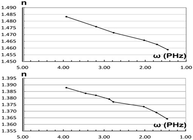 |
Figure 3 The refractive index changes of pure water (top) and human hemoglobin (bottom) with angular frequency ω. |
Thus, in order to simplify the calculation, we assume that the refractive index of the turbid media (including body tissues) changes linearly with respect to the angular frequency. Because there is a large amount of water in the body as mentioned before, such an approximation is acceptable. Thus, we have

where  is the refractive index of the turbid medium corresponding to the angular frequency
  Thus, because of Eq. (1), we have

where  is a proportion constant. Thus, the phase item in the square brackets of Eq. (3) can be written as, when

Because  is much less than
  , and even
  is still less than
  in many situations, Eq. (14) can be written approximately as

Replacing the phase item in the square bracket of Eq. (3) by Eq. (15), and using the triangular series sum formula, the composite light intensity of the multibeam interference of the N beams becomes
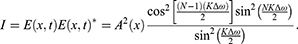
where 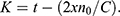 When
When  becomes zero, the value of
  goes to the maximum. The results of numerical calculations by Eq. (16) are shown in Figure 4 and Table 1. In Figure 4,
  changes with parameter
  Using
Using  as the unit of transverse coordinate is for avoiding complicated theoretical derivations, and the essential characteristics of the multibeam interference in dispersion medium can still be seen. The
  curve in Figure 4 may be regarded as the change of the composite light intensity of
  beams with respect to
  at the moment when the inner light layer is recreated. In the calculations,
  In order to show the width of the composite light intensity maximum clearly, we just take
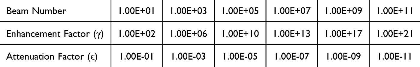 |
Table 1 Light Intensity Enhancement With Different Beam Number N in Human Body |
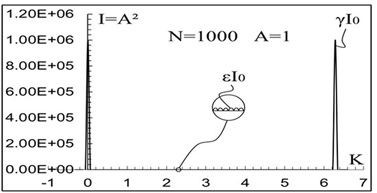 |
Figure 4 The composite light intensity change of the multibeam interference in an optical dispersive medium. |
In Table 1, N is the beam number.  is the enhancement factor of the composite intensity maximum
 is the attenuation factor of the remaining composite intensity
  between two composite intensity maximums (see Figure 4).
  is the incident intensity of each beam of the
  beams. We see that
  increases rapidly with increases in
  . For example, when
  or
or 
 can be more than 13 or even 21 orders of magnitude higher than
  , respectively. If considering the attenuation of the remaining composite intensity,
  can be more than ~20 or even ~33 orders of magnitude higher than
  , respectively.
In the human body, since the different tissues have different absorption and scattering coefficients, and different refractive indexes, we may only use the average values of these parameters for calculations. The absorption and scattering coefficients of muscle are used as the average values of body tissues temporarily. The absorption and (reduced) scattering coefficients of human forearm muscle are  per millimeter and
  per millimeter at wavelength
  nanometers.4 In the light absorption and scattering media including human body tissues, the light intensity changes with traveling distance (operating depth)
  as8
as8
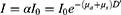
From Eq. (17), we get illuminating light intensity change with traveling distance (operating depth) shown in Table 2. In Eq. (17) and Table 2,  is the light intensity attenuation rate. We can see that the laser light intensity decays with
  rapidly. For example, when
  millimeters or
  millimeters,
  can be less than 10 or even 19 orders of magnitude lower than
  , respectively.
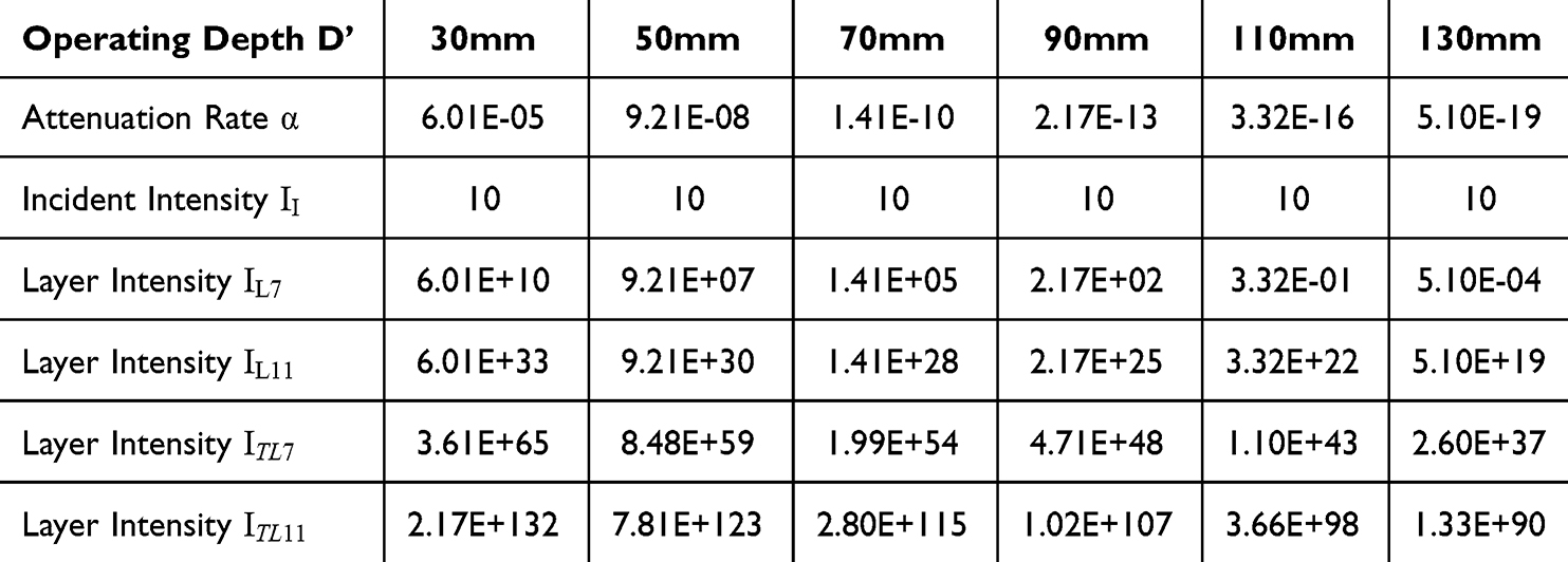 |
Table 2 Light Intensity Change With Different Operating Depths D’ in Human Body |
Comparing Table 1 and Table 2, we see that, when the number  is large, the absolute value of the enhancement factor
  may be larger than the absolute value of the attenuation rate
  , and even the operating depth is relatively deep. Therefore, the laser light intensity decay caused by the light absorption and scattering in the human body may be compensated by multibeam interference effectively.
We suppose that after passing the negative dispersive fiber, the width of a laser pulse has been broadened and so its peak intensity drops to be  . Then let this broadened pulse, that is, the
  beams with reduced composite intensity enter the body. After traveling the distance
  , the composite intensity maximum of the
  beams becomes
  .
.
Due to the multibeam constructive interference, an inner light layer is formed in the body. If the light layer is formed at the depth of  millimeters or
  millimeters, the intensity of the light layer will become
  or
or  from
from  . Here,
  or
or  is the intensity of the light layer formed at the depth of
  millimeters or
  millimeters in body, respectively.
Because the composite intensity of the  beams is first attenuated by light absorption and scattering in the traveling path, then it is enhanced by the multibeam constructive interference, we have


In Eq. (19),  is the composite intensity maximum of the
  beams when considering both effects of the enhancement factor
  and attenuation factor
  . According to Eq. (18) and Eq. (19), we get the intensities of the formed light layer at different operating depths also shown in Table 2.
In Table 2,  ,
,  ,
,  and
and  express the light intensities of the formed light layer under two multibeam interference conditions corresponding to two beam numbers or values of
  .
.  and
and  correspond to
  .
.  and
and  correspond to
  . In addition,
  and
and  are the results when considering the influences of the attenuation rate
  and enhancement factor
  .
.  and
and  are the results when considering the influences of the attenuation rate
  , the enhancement factor
  and attenuation factor
  . In Table 2, the intensity units of
  ,
,  ,
,  ,
,  and
and  are milliwatts per square centimeter.
We suppose the initial incident composite intensity of the  beams entering the human body is
  milliwatts per square centimeter. Since the composite intensity of the incident laser beams is only 10 milliwatts per square centimeter, the body tissues in the laser beam traveling path will certainly not be injured. Then, according to Eq. (18) and Eq. (19), the intensities of
  ,
,  ,
,  , and
, and  with different operating depths
  are calculated and are shown in Table 2. We can see that the larger the number
  , the higher the created operating light intensity, and the deeper the operating depth.
The number N is determined by the frequency component number of the used laser pulse, which depends on the longitudinal mode number of the mode-locked laser. In order to obtain a large number  , the laser must have a wide frequency range
  and a narrow frequency interval
  because

Obtaining a wide frequency range has a limitation because most optical media have a window where the light absorption and scattering are low. For human tissues, the width of such a window is about  Hertz, which corresponds to a light wavelength range from 700 nanometers to 1200 nanometers.8 The frequency interval
  of the mode-locked laser depends on laser cavity length
  as10
as10

where  is the refractive index of the lasering medium in the laser cavity, and
  is the light speed in vacuum. The choice of using a fiber laser allows for ultra-long cavity length. From Eq. (20) and Eq. (21), when
  ,
,  is
is  ,
,  and
and  corresponding to the laser cavity lengths of
  kilometer,
  kilometers and
  kilometers, respectively. Currently, obtaining fiber lasers with ultra-long lengths (using optical fiber), such as even
  kilometers, is possible.25
Because the obtainable number  may be more than 1
 or even
  , from Table 2, the light layer intensity, that is, the obtainable laser operating intensity may be much higher than
  watts per square centimeter at depths deeper than
  millimeters and even
  millimeters. The intensity of
  watts per square centimeter can do almost all kinds of laser surgeries.1,2,26
However, considering that the absorption and scattering coefficients of some body tissues are larger than those of muscle,27 and the described calculations are approximate, the achievable safe and maximum operating depth in the human body is estimated conservatively as 70 millimeters here. Of course, there is a good possibility for the depth value to be up to 130 millimeters.
As mentioned above, the thickest part of the average human body is about 250 to 300 millimeters at the chest (measured vertically from the front to the back when the person is lying horizontally on the bed). When laser beams enter the body from the front, the maximum depth can reach 130 millimeters, and similarly, when the beams enter from the back, the maximum depth can also reach 130 millimeters. Therefore, the total depth the laser beams can reach is 260 millimeters. Since the thickness of other parts (measured vertically when the person lies horizontally) of the body will not exceed the chest thickness, if the achievable operating depth is near 130 millimeters, the method and apparatus have a good possibility of treating the whole body. This is because the laser beams can enter the body lying horizontally on the bed from above and below, respectively.
At this stage, the technical parameters of this non-invasive laser surgery apparatus can only be estimated as no apparatus is being manufactured currently. The key component of the apparatus is the mode-locked fiber laser, which requires a long fiber to build the necessary laser resonator. As described above, the fiber length will be 1 to 10 kilometers or even longer to obtain deeper safe operating depth with higher laser power. However, because the laser resonator can be made of industrial optical bare fiber which weighs in at just 30 milligrams per meter,28 that is, 30 grams per kilometer, the total weight of the fiber laser should be no more than 20 kilograms and have a volume of about 0.5 cubic meters. Compared to the fiber laser, the weight and volume of other components used in the apparatus, such as negative dispersion fiber, operating depth-adjusting prisms, and focusing lenses, are smaller. Therefore, excluding the bed for the patient, the total weight and volume of the apparatus should be no more than 50 kilograms and 1 cubic meter. The apparatus’ laser has a wide spectrum range from near-infrared to visible. The average operating light power of the apparatus is about 50 watts. The operating precision is approximately 1 micron in the lateral direction and 1 millimeter in the longitudinal direction.
Conclusion
In this paper, the method and apparatus of non-invasive laser surgery with deep operating depth are investigated theoretically. The principle of the method has a solid physical basis. By using multibeam destructive interference, the composite intensity of laser beams becomes very low in the body, which reduces light absorption and scattering and avoids injuries to layers of skin and undesired tissues. Meanwhile, by using multibeam constructive interference, an inner light layer with high intensity may be formed in the body as a scalpel to treat target tissue. The designed apparatus has very high surgery precisions of around  micron in the lateral direction and about 1 millimeter in the longitudinal direction. Calculations show that the achievable safe non-invasive operating depth can be more than
  millimeters with good possibility to reach up to
  millimeters in the human body.
As a special type of surgery, non-invasive laser surgery uses photo-chemical, photo-thermal, photo-ablative, and photo-mechanical effects to irradiate, coagulate, ablate, and even vaporize various tissues in the human body,1,2 such as using irradiation to enhance medicinal effects to desired tissues, using coagulation to control bleeding, using ablation to cut cancerous tumors, using thermal expansion to shatter intraluminal stones, and even using vaporization to eliminate harmful deposits in the trachea, esophagus, intestine, stomach, and blood vessels. Therefore, this type of laser surgery will have important, widespread, and irreplaceable applications in the future.
The excellent performance of the investigated method and apparatus is not strange. Multibeam interference has demonstrated its astonishing abilities in the past, such as the fastest ever man-made event of a light pulse of attoseconds, and the strongest ever man-made event of light power of terawatts. It will make a great contribution to the millions of patients in the future.
Acknowledgment
The author is grateful for the help from Mr. Shangqing Liu from the Willow Optics Corp. in Toronto, Canada.
Author Contributions
The author made a significant contribution to the work reported, whether that is in the conception, study design, execution, acquisition of data, analysis and interpretation, or in all these areas; took part in drafting, revising or critically reviewing the article; gave final approval of the version to be published; have agreed on the journal to which the article has been submitted; and agree to be accountable for all aspects of the work.
Funding
The author declares no funds, grants, or other support was received during the preparation of this manuscript.
Disclosure
Partial content of this paper was presented at the SPIE Conference “SPIE Photonics Europe, 2022, Strasbourg, France” as a conference talk with interim findings. The partial content of this paper was published in “Proceedings of SPIE, Vol. 12142”: Hyperlink with doi:10.1117/12.2623912.
Ms Joyce Liu reports a patent Apparatus of Inner Light Layer Formed by Multibeam Interference for Processing Object in Optical Turbid Medium pending to N/A. The author declares no competing interests in this work.
References
1. Khalkhal E, Rezaei-Tavirani M, Zali MR, Akbari Z. The evaluation of laser application in surgery: a review article. J Lasers Med Sci. 2019;10(Suppl 1):S104–S111. doi:10.15171/jlms.2019.S18
2. Shokrollahi K, Raymond E, Murison MSC. Lasers: principle and surgical applications. J Surg. 2004;2(1):28–34. doi:10.1016/S1743-9191(06)60023-X
3. Huang Z. A review of progress in clinical photodynamic therapy. Technol Cancer Res Treat. 2005;4(3):283–293. doi:10.1177/153303460500400308
4. Gratton E, Fantini S, Franceschini MA, Gratton G, Fabiani M. Measurements of scattering and absorption changes in muscle and brain. Phil Trans R Soc B Boi Sci. 1997;352(1354):727–735. doi:10.1098/rstb.1997.0055
5. Liu J. Laser energy delivery method and apparatus using multiple beam interference. Proc SPIE 121420. 2022;12142:121420V1–121420V17.
6. Bashkatov AN, Berezin KV, Dvoretskiy KN, et al. Measurement of tissue optical properties in the context of tissue optical clearing. J Biomed Opt. 2018;23(9):091416.1–091416.31. doi:10.1117/1.JBO.23.9.091416
7. Greivenkamp JE. Multiple Beam Interference. Handbook of Optics. 1995;2:2.29–2.36.
8. Setchfield K, Gorman A, Simpson HRW, Somekh MG, Amanda JW. Relevance and utility of the in-vivo and ex-vivo optical properties of the skin reported in the literature: a review. Biomed Opt Express. 2023;4(7):3555–3583. doi:10.1364/BOE.493588
9. Fork RL, Martinez OE, Gordon JP. Negative dispersion using pairs of prisms. Opt Lett. 1984;9(5):150–152. doi:10.1364/OL.9.000150
10. Silfvast WT. Lasers. Handbook of Optics. 1995;11:11.20–11.22.
11. Woodward RL. Dispersion engineering of mode-locked fiber lasers. J Opt. 2018;20(3):1–18. doi:10.1088/2040-8986/aaa9f5
12. Ouyang G, Xu Y, Yariv A. Theoretical study on dispersion compensation in air-core Bragg fibers. Opt Express. 2002;10(17):899–908. doi:10.1364/OE.10.000899
13. Bouk AH, Cucinotta A, Poli F, Selleri S. Dispersion properties of square-lattice photonic crystal fibers. Opt Express. 2004;12(5):941–946. doi:10.1364/OPEX.12.000941
14. Prabhakar G, Peer A, Rastogi V, Kumar A. Large effective-area dispersion-compensating fiber design based on dual-core microstructure. Appl Opt. 2013;52(19):4505–4509. doi:10.1364/AO.52.004505
15. Engeness TD, Ibanescu M, Johnson S, et al. Dispersion tailoring and compensation by modal interactions in omni guide fibers. Opt Express. 2003;11(10):1175–1196. doi:10.1364/OE.11.001175
16. Smith WJ. Optical materials and interference coatings. In: Modern Optical Engineering. Vol. 7. New York: McGRAW-Hill; 2000:176.
17. Pogue BW, Patterson MS. Review of tissue simulating phantoms for optical spectroscopy, imaging and dosimetry. J Biomed Opt. 2006;11(4):02.1–02.16. doi:10.1117/1.2335429
18. Marathay AS. Diffraction. Handbook of Optics. 1995;3:3.22–3.25.
19. Carters WH. Coherence theory. Handbook of Optics. 1995;4:
20. Bunge CA, Beckers M, Lustermann B. Polymer Optical Fibres, Fibre Types, Materials, Fabrication, Characterization and Applications. Elsevier Ltd, Woodhead Pub; 2017:47–118.
21. Seawater intrusion and mixing in estuaries. Coastal Wiki. Available from: https://www.coastalwiki.org/wiki/Seawater_intrusion_and_mixing_in_estuaries.
22. Huszka G, Gijs MAM. Super-resolution optical imaging: a comparison. Micro and Nano Eng. 2019;2:7–28. doi:10.1016/j.mne.2018.11.005
23. Inoue S, Oldenbourg R. Microscopes. Handbook of Optics. 1995;17.
24. Haynes WM, Lide DR, Bruno TJ. CRC Handbook of Chemistry and Physics.
25. Aston University. World’s Longest Laser-270 km Long Created. Science Daily. 2009. Available from: www.sciencedaily.com/releases/2009/12/091215160000.htm.
26. Jiao L, Wang J, Fan Y, Yang Z. Porcine skin damage thresholds and histological damage characteristics from 1319-nm laser radiation. J Biomed Opt. 2019;24(9):1–9. doi:10.1117/1.JBO.24.9.095003
27. Sandell JL, Zhu TC. A review of in-vivo optical properties of human tissues and its impact on PDT. J Biophotonics. 2011;4(11–12):773–787. doi:10.1002/jbio.201100062
28. Mitschke F. Fiber Optics: Physics and Technology. 2016:12.
 © 2025 The Author(s). This work is published and licensed by Dove Medical Press Limited. The
full terms of this license are available at https://www.dovepress.com/terms
and incorporate the Creative Commons Attribution
- Non Commercial (unported, 3.0) License.
By accessing the work you hereby accept the Terms. Non-commercial uses of the work are permitted
without any further permission from Dove Medical Press Limited, provided the work is properly
attributed. For permission for commercial use of this work, please see paragraphs 4.2 and 5 of our Terms.
© 2025 The Author(s). This work is published and licensed by Dove Medical Press Limited. The
full terms of this license are available at https://www.dovepress.com/terms
and incorporate the Creative Commons Attribution
- Non Commercial (unported, 3.0) License.
By accessing the work you hereby accept the Terms. Non-commercial uses of the work are permitted
without any further permission from Dove Medical Press Limited, provided the work is properly
attributed. For permission for commercial use of this work, please see paragraphs 4.2 and 5 of our Terms.