Back to Journals » Nanotechnology, Science and Applications » Volume 7
New materials graphyne, graphdiyne, graphone, and graphane: review of properties, synthesis, and application in nanotechnology
Authors Peng Q, Dearden A, Crean J, Han L, Liu S, Wen X, De S
Received 27 December 2013
Accepted for publication 3 February 2014
Published 10 April 2014 Volume 2014:7 Pages 1—29
DOI https://doi.org/10.2147/NSA.S40324
Checked for plagiarism Yes
Review by Single anonymous peer review
Peer reviewer comments 4
Qing Peng,1 Albert K Dearden,2 Jared Crean,1 Liang Han,1 Sheng Liu,3 Xiaodong Wen,4,5 Suvranu De1
1Department of Mechanical, Aerospace and Nuclear Engineering, Rensselaer Polytechnic Institute, Troy, NY, USA; 2Department of Physics, Applied Physics, and Astronomy, Rensselaer Polytechnic Institute, Troy, NY, USA; 3Institute for Microsystems, School of Mechanical Engineering, Huazhong University of Science and Technology, Wuhan, People's Republic of China; 4State Key Laboratory of Coal Conversion, Institute of Coal Chemistry, Chinese Academy of Sciences, Taiyuan, People's Republic of China; 5Synfuels China Co, Ltd, Huairou, Beijing, People's Republic of China
Abstract: Plenty of new two-dimensional materials including graphyne, graphdiyne, graphone, and graphane have been proposed and unveiled after the discovery of the "wonder material" graphene. Graphyne and graphdiyne are two-dimensional carbon allotropes of graphene with honeycomb structures. Graphone and graphane are hydrogenated derivatives of graphene. The advanced and unique properties of these new materials make them highly promising for applications in next generation nanoelectronics. Here, we briefly review their properties, including structural, mechanical, physical, and chemical properties, as well as their synthesis and applications in nanotechnology. Graphyne is better than graphene in directional electronic properties and charge carriers. With a band gap and magnetism, graphone and graphane show important applications in nanoelectronics and spintronics. Because these materials are close to graphene and will play important roles in carbon-based electronic devices, they deserve further, careful, and thorough studies for nanotechnology applications.
Keywords: two-dimensional materials, graphene-like structures, properties and synthesis, nanotechnology applications, graphyne, hydrogenation of grapheme
Introduction
Found in almost all known life forms, carbon provides the basis for life on Earth. Carbon has various hybridized states (sp, sp2, sp3) and can form diverse bonding, with the ability to bind to itself and to nearly all elements. As a consequence, carbon has numerous allotropes1,2 such as graphene,3,4 fullerenes,5 carbon nanotubes,6 nanorings,7 and nanobuds.8 Synthesis and discovery of new carbon phases with high stability, novel bonding characteristics, unique properties, and applications will be an ongoing effort for theoretical, synthetic, and material scientists.2 Ever since graphene was first created in 2004,9 many claim that it can be used in a host of device applications, carbon-based electronics, even rivaling silicon as the electronics material of choice in the future.10
As a monatomic layer of carbon atoms in a honeycomb lattice,11 graphene is one of the strongest materials ever tested with tensile strengths greater than 100 GPa and a tensile modulus of 1 TPa.12 With high carrier mobility and saturation velocity, graphene has promising applications in ultrahigh speed radiofrequency electronics.13–15 Plenty of new two-dimensional materials16,17 were proposed and unveiled, such as hexagonal boron nitride monolayers,18 hybrid graphene/boron nitride monolayers,19–22 thallium nitride monolayers,23 zinc oxide monolayers,24 aluminum nitride monolayers,25 germanium carbide monolayers,26 gallium nitride monolayers,27 silicene,28–30 molybdenum disulfide,31 and graphene oxide32 after the discovery of the “wonder material” graphene. As new forms of non-natural carbon allotropes related to graphite/graphene, graphyne (Figure 1) and graphdiyne have been the subjects of interest due to their unique structures and intriguing electronic, optical, and mechanical properties,33,34 as well as promising nanoelectronics and energy storage applications.35 A very recent study indicates that graphyne is potentially superior to graphene in directional electrical conductivity.10
 | Figure 1 Geometry of γ-graphyne. |
Although the unique electronic (“Dirac cone” like) and mechanical properties of graphene have amazed researchers, a zero band gap limits its applications in field effect transistors with a high on–off ratio, as well as logic and high speed switching devices, since the current can never be turned off completely.36–39 However, hydrogenation is a chemical modification method intended to open the band gap of graphene.40–45 As a derivative of graphene, graphane is a theoretical nonmagnetic semiconductor with an energy gap formed by 100% hydrogenation of graphene with stoichiometry CH. These hydrogen atoms, which alternate direction along the graphane sheet, transform the carbon lattice from sp2 to sp3 hybridization. Graphane can also be converted back into graphene through annealing. It turns out that such hydrogenation greatly reduces the in-plane stiffness by about 30%.46 Through a reversible process, graphane opens new possibilities for the use of carbon based materials in applications involving manipulation of electronic properties,41 thermal conductivity,47 hydrogen storage,48 and magnetization.49,50
Since the process by which graphene can be transformed into graphane is reversible, many intermediate forms can exist. Here, graphone is the midpoint between graphene and graphane in which the graphene sheet is only partially hydrogenated. Unlike graphane (100% hydrogenation) and graphene (0% hydrogenation), graphone is a graphene sheet with 50% hydrogenation and stoichiometry C2H. Additionally, the hydrogen atoms are only on one side of the carbon sheet, resulting in a mixture of hybridized sp2 and sp3 carbon atoms. The synthesis of graphone is achieved by desorption of hydrogen from graphane.51
With the discovery of these new materials, extensive studies were conducted on exploring their properties and applications. We have to limit our focus to the mechanical, physical, and chemical properties, and their applications in nanotechnology in this short review.
Graphyne
Properties
Graphyne is an allotrope of carbon. Its structure is a one atom thick planar sheet of sp and sp2 bonded carbon atoms arranged in a crystal lattice. There are more two-dimensional planar carbon structures besides graphene, such as the so-called graphyne10,52–54 which has also been predicted to exist, but up to now only molecular fragments have been synthesized.55,56 Indeed, there may be a vast number of possible graphynes (Figures 1 and 2), each with the double and triple bonds in slightly different arrangements (Figure 2). The existence of graphyne was conjecture before 1960,57 and attracted attention after the discovery of fullerenes. Theorists have been studying graphynes since the 1980s.
 | Figure 2 Structures of graphene and graphyne. |
Graphyne is a variation of graphene that has acetylenic linkages connecting the hexagons of graphene, as demonstrated in Figure 1. Graphyne was first proposed in 1987 by Baughman et al as part of a larger investigation into the properties of new forms of carbon that had been sporadically reported, but not systematically investigated.52 Graphyne is of particular interest due to its electronic structure, which is quite different from that of existing materials, including other carbon based materials such as diamond and graphite. The most common form of graphyne is γ-graphyne, although several others have been studied as well.10 If unspecified, γ-graphyne is assumed in this paper. The γ-graphyne unit cell consists of 12 carbon atoms arranged in a closed figure.
One of the attractive features of graphyne is its mechanical properties, both in infinite sheets58–60 and in nanoscale flakes.59 Cranford and Buehler59 have investigated the mechanical properties of graphyne flakes using the first principles based ReaxFF61 interatomic potential. A short time step of 0.2 femtoseconds was used to accurately capture the high frequency vibrations present in acetylenic bonded systems. Energy minimization of the unstrained system indicates stability, with very consistent bond lengths of 1.19 Å for triple bonds, and 1.48 Å and 1.49 Å for single and aromatic bonds, respectively. The constant strain rate approach whereby the sheet was strained at a constant rate while the virial stress was calculated for the interior volume of the sheet, avoiding any boundary effects, yielded the armchair modulus as 532.5 GPa and the zigzag modulus as 700.0 GPa, whereas the energy minimization approach gave 629.4 GPa and 772.0 GPa, respectively, which are significantly different. The energy minimization approach strained the sheet a specified amount and performed energy minimization on the strained system while calculating the elastic energy density. The authors chose to pursue this method in addition to the constant strain rate approach because it does not contain strain rate dependence, although it is not a truly dynamic method, so dynamic phenomena such as failure are not accurately modeled. The calculated values for the ultimate stresses are much more consistent. In the armchair and zigzag directions they are approximately 46 GPa and 104 GPa, respectively. The differing Young’s modulus values indicate some strain rate dependence; however, the similarity of the ultimate stresses indicated that it does not affect the breaking strength of the material. It should be noted that the conversion of N/m to GPa used a thickness value of 3.20 Å, which was determined to be the minimum system potential energy with respect to interlayer distance.59
Zhang et al60 investigated graphyne using molecular dynamics (MD) with the Adaptive Intermolecular Reactive Empirical Bond Order (AIREBO) potential, a hydrocarbon potential that is capable of modeling the formation and breaking of bonds, as well as bonds of different order. Using a constant strain rate approach analogous to Cranford and Buehler,59 ultimate stresses of 63.17 GPa in the armchair direction, and 49.78 GPa in the zigzag direction are reported,60 compared to 46 GPa and 104 GPa, respectively, from the first study59 using ReaxFF. Because ReaxFF is based on a hybrid potential bond order scheme, using data from first principle quantum mechanics, it is a more accurate description method of the interactions between atoms than AIREBO, although it is more computationally expensive. It is also noteworthy that one study60 used a finite sized sheet of graphyne called a ribbon, while the other study59 used periodic boundary conditions to create an infinite sheet.
Using density functional theory (DFT) calculations, Peng et al58 employed a quasistatic method analogous to the energy minimization method employed by Cranford and Buehler59 to determine the elastic constants of graphyne up to the fifth order. The constants themselves were determined by expressing the components of the Piola-Kirchhoff stress tensor as a Taylor series and curve fitting the stress strain values obtained from DFT calculations.58 Fourteen independent nonzero components were found, and the nonsymmetry indicates that graphyne must be anisotropic. The ultimate strengths were also found to be 55.8 GPa for armchair and 58.8 GPa for zigzag, using a thickness of 3.20 Å from Cranford and Buehler.59 The armchair strength is similar to previous studies;60 however, the zigzag strength is not. Zhang et al60 reported a somewhat lower value, while Cranford and Buehler59 reported a significantly higher value.
While graphyne itself is not stable in finite form, the edges of the flake are terminated with hydrogen atoms to satisfy the bonding requirements of the carbon atoms on the edge of the flake. In this configuration, the ultimate stress is found to be 48.2 GPa for the armchair direction, and 107.5 GPa in the zigzag direction, with corresponding stiffness of 532.5 GPa and 700 GPa, respectively.59
The electronic properties of graphyne have also been studied. Graphyne ribbons with finite width have been investigated using first principle calculations and it has been shown that graphyne nanoribbons have band gaps in the semiconductor range, from 0.59–1.25 eV for ribbons having widths of 1 repeat unit to 8 repeat units.62 An investigation has shown the band gap of infinite sheets of graphyne to respond to mechanical strain.34 A tensile strain of 0.15 causes the band gap to increase by 1 eV, and conversely, compressive strain of 0.1 reduces the band gap by 0.3 eV.
In addition to the mechanical means of affecting the electronic properties of graphyne, chemical means have been explored. From a physical chemistry perspective, adsorbing transition metals onto sheets of graphyne have been shown to cause significant changes in the overall behavior of the material.63 When chromium and iron are adsorbed, graphyne becomes a spin polarized metal rather than a semiconductor. Adsorption of other transition metals can result in either a narrow gap semiconductor or a spin polarized half semiconductor. These absorptions are energetically favorable, which indicates they are possible to accomplish with an actual sheet of graphyne.
Studies have also shown that graphyne has unusual optical properties. The complex dielectric function has been calculated for graphyne as a function of the energy adsorbed for an electric field parallel and perpendicular to the graphyne sheet.34 These two cases show distinctly different responses, which opens the possibility of using graphyne in sensing applications where directionality is important. The responses are particularly different across the 9 eV mark: below 9 eV, the parallel electric field has the greatest response, above 9 eV, the perpendicular field has the greatest response.
Synthesis
The first steps toward the preparation of extended graphynes have been proposed and developed (Figure 3).55,64 Especially, in 1994, Diederich55 proposed that the success of attempts to construct new carbon phases is largely determined by high quality organic synthesis, such as modern acetylene chemistry, advanced by powerful new organometallic synthetic methodologies. In addition, it may be important to be receptive to unusual methods produced by other disciplines if unprecedented and unconventional synthetic methods are to be discovered.
 | Figure 3 Synthetic approaches to graphyne from organic compounds. |
In 2008, Haley65 presented the synthetic strategies toward and optoelectronic properties of substructures of the non-natural, planar carbon networks graphyne, which is based on the dehydrobenzo12 annulene framework65 as depicted in Figure 4. He also pointed out that it is necessary to extensively develop and utilize metal catalyzed cross coupling, homocoupling, and metathesis reactions to synthesize the targets.
 | Figure 4 Synthetic strategies toward graphyne subunits. |
Future synthesis of graphyne materials may involve the use of surfaces as supports and templates in approaches related to the recently reported synthesis of graphene on metal surfaces by chemical vapor deposition of organic precursor molecules.66 Whether attempts to synthesize extended graphyne materials are worthwhile depends on the properties such materials would have, in particular, on their electronic properties. We should stress the fact that graphyne has not been made in the laboratory in significant quantities as yet; only trace amounts have been fabricated.
Applications
Although graphyne has yet to be synthesized well, its properties are promising for several applications, such as nanofillers, transistors, sensors, semiconductor metal hybrids, anisotropic conductors, and desalinators.
Nanofillers
The mechanical properties of graphyne show strong promise for its use as a nanofiller in composite materials. Small flakes of graphyne can be dispersed in a polymer matrix to increase both stiffness and strength. The edge bonding of the graphyne sheets could facilitate the adhesion of the filler molecules to the matrix, which will increase the effectiveness of the filler by preventing separation of the matrix and the graphyne flake. This forestalls one of the primary failure modes of composites, ie, the separation of the inferior matrix from the high performance fiber. Another promising indication is the high surface adhesion energy of graphyne, 223.5 mJ/m2,59 which provides a second mechanism to adhere the graphyne flakes to the matrix. Although graphyne flakes exhibit anisotropic behavior, mixing into the matrix will result in random orientation of the flakes, giving the resulting composite isotropic properties. In this way, graphyne can be substituted for existing fillers such as short graphite fibers.
Transistors
Computational studies clearly indicate that the band gap of graphyne is tunable by mechanical means, which lends itself to easy manufacturing of transistors with different characteristics that are dependent on band gap, such as the on–off ratio. It also enables these properties to be determined much later in the manufacturing process than is possible with conventional semiconductors, the properties of which are determined during the chemical doping process. Graphyne semiconductor properties can be determined by the fabrication size.
Sensors
Electromechanical coupling is a highly desirable property for a variety of semiconductor devices. Mechanical strain is relatively easy to apply and measure, allowing easy modification of the material for a particular application. Additionally, graphyne exhibits a large elastic strain region which enables the material to be strained, relaxed to its original shape, and strained again without permanent deformation, enabling resilient electromechanical coupling which can be useful in a variety of applications including temperature sensing.
Semiconductor metal hybrids
Besides mechanically tuning the band gap of graphyne, which is reversible, creating narrow band semiconductors and spin polarized half semiconductors is very useful since the semiconductor phase is substantially different from the metal phase, opening the route to make semiconductor metal hybrids on a single monolayer using graphyne for both transistor and the interconnecting metal in Very-Large-Scale Integration fabrication. Because graphyne is a single sheet, chemical treatment can be done as a final step in the fabrication process without the limited penetration that would occur with three-dimensional materials. Additionally, the excellent mechanical properties of graphyne,58 although likely to be somewhat altered by adsorption of other atoms, remain significant in the prevention of mechanical failure that can result from repeated thermal expansion and contraction that occurs with current technology.
Anisotropic conductor
The models for graphyne show that it has the potential for Dirac cones on its double and triple bonded carbon atoms. Due to the Dirac cones, there is a single point in the Fermi level where the conduction and valence bands meet in a linear fashion. The advantage of this scheme is that electrons behave as if they have no mass, resulting in energies that are proportional to the momentum of the electrons. Like in graphene, hexagonal graphyne has electric properties that are direction independent.10
Due to the symmetry of the proposed rectangular 6,6,12-graphyne, the electric properties would change along different directions in the plane of the material. The directional dependency of 6,6,12-graphyne could allow for electrical grating at the nanoscale. This will help with designing faster transistors and a variety of electronic components which process one way current.
Desalinator
Most of the water on earth is salt water, or sea water, which takes up about 97.5% of the total global water.67 Desalination that produces clean fresh water from sea water, namely desalination, holds the promise of solving the global water shortage for drinking, agriculture, and industry. The double and triple bonds in graphyne create holes between the carbon atoms. These holes are large enough for water molecules to pass through. However, they are not big enough for sodium and chlorine ions, which are larger because they attract a shell of water molecules since they are charged. By MD simulations and first principles modeling (Figure 5), it was found that pristine graphyne can achieve 100% rejection of ions in sea water, including Na+, Cl−, Mg2+, K+, and Ca2+, at an exceptionally high water permeability, about two orders of magnitude higher than that of commercial state-of-the-art reverse osmosis membranes with a salt rejection of 98.5%.68 This complete ion rejection by graphyne, independent of the salt concentration and the operating pressure, is revealed to originate from the significantly higher energy barriers for ions than for water.68 This intrinsic specialty of graphyne provides a new possibility for the efforts to alleviate the global shortage of fresh water and other related environmental problems.
 | Figure 5 Schematic diagram of the computational system for salination of graphyne. |
Graphdiyne
Properties
After the discovery of graphene and the prediction of graphyne, additional two-dimensional materials have received significant research attention. Among those is graphdiyne, a variant of graphyne that contains two acetylenic linkages in each unit cell rather than the one linkage as in graphyne, as depicted in Figure 6.69 The two acetylenic linkages double the length of the carbon chains connecting the hexagonal rings.70 As a result, graphdiyne does not share graphyne’s exceptional mechanical properties. Graphdiyne is a softer material than either graphyne or graphene, with an in plane stiffness of 120 N/m, which is equivalent to a Young’s modulus of 375 GPa, if a thickness of 0.320 nm is assumed.70
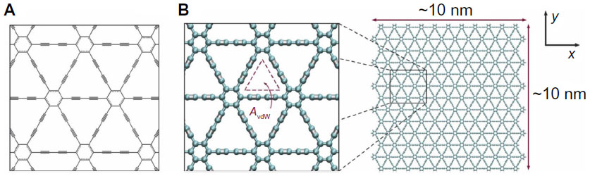 | Figure 6 Structure of graphdiyne. (A) Chemical structure of graphdiyne, a two-dimensional structure of sp–sp2-hybridized carbon atoms with characteristic hexagons of graphene by diacetylenic (single- and triple-bond) linkages forming a repeating and regular nanomesh. (B) Full atomistic model of graphdiyne depicting the atomistic triangular pores, with van der Waals openings (AvdW) on the order of 6.3 A2. The graphdiyne membrane employed here has dimensions on the order of 10 nm ×10 nm (approximately 250 exposed pores); graphdiyne edges are terminated with hydrogen atoms for stability. |
Graphdiyne was first predicted by Haley et al in 1997.71 Early work was focused on synthesizing the material from similar organic molecules and using computational models of similar materials to estimate the properties of graphdiyne itself.71 Graphdiyne is part of the graphyne family; however, due to its interesting properties, it is typically considered separately.70,72
Performing ab initio calculations using the Vienna ab initio simulation package (VASP), Pei72 predicted the in plane stiffness and calculated the Poisson’s ratio as 0.453. In a strain free state, the band gap is calculated to be 0.47 eV and 1.12 eV using two different methods. The first method, the generalized gradient approximation with the Perdew-Burke-Ernzerhof exchange correlation functional tends to underestimate the band gap, whereas the second method, using the Heyd-Scuseria-Ernzerhof exchange correlation functional tends to overestimate the band gap. These results bind the range of possible band gaps, limiting it to nonzero values, which presents a distinct advantage over graphene for transistors with high on–off ratios.
Additionally, the band gap was shown to be proportional (with a positive proportionality constant) to externally applied strain.72 The band gap varied from 0.28 eV with ε=−0.05 to 0.71 eV at ε=0.06, with the strain free value of 0.47 eV. This shows the band gap of graphdiyne to be readily tunable for specific applications. Additionally, the near massless behavior of electrons, as predicted by the Dirac cone shape of the electron band gap, is verified, resulting in a very attractive semiconductive material.
Further investigation was conducted by Cui et al73 using the Projector Augmented Wave method. Equal biaxial strain was shown to increase the band gap, confirming the previous results, and uniaxial strain was shown to decrease the band gap by changing the electron densities around the carbon atoms in the diacetylenic linkages. The coupling of mechanical loading in electronic properties is very promising for, and useful in, engineering applications.
Because of the similarity of graphyne and graphdiyne, using a thickness of 3.20 Å for both, this is a reasonable approximation for qualitative comparison. The stiffness of graphdiyne is approximately 30% that of graphyne and its strength is expected to be noticeably reduced.69,72 These reductions are a direct result of the extra acetylenic linkage which effectively reduced the atomic coordination number, resulting in weaker bonding. It is also noteworthy that the mechanical behavior of graphdiyne appears to be isotropic.72 For these reasons, graphdiyne is not suitable for use in nanocomposites.
Although its mechanical properties are lackluster, the electronic properties of graphdiyne are predicted to be exceptional. Graphdiyne has been synthesized recently,72 but many properties are predicted through computational rather than strictly experimental means. Of particular interest is the low effective electron mass that results from the Dirac cone structure of the electron bands. Effective masses on the order of 0.08 of the mass of an actual electron are reported, and the band gap is in the semiconduction range.72
Graphdiyne nanoribbons have been studied to determine the effects of finite width on the properties of the material. The band gap was shown to increase with decreasing ribbon width.74 For both armchair and zigzag orientations the trend was similar; however, there was a noticeable offset between the two data sets. Additionally, as width increases, the two trends appeared to converge, indicating infinite sheets of graphdiyne would not exhibit directional dependence. The same study also investigated the response of the band gap to electric fields. An electric field perpendicular to the nanoribbon was shown to decrease the band gap, eventually closing it at a field strength 0.11 V/Å.
Synthesis
Haley65 presented the synthetic strategies toward, and optoelectronic properties of, substructures of the non-natural, planar carbon networks graphdiyne, which is based on the dehydrobenzo18 annulene framework,65 in 2008. He pointed out that it is necessary to extensively develop and utilize metal catalyzed cross coupling, homocoupling, and metathesis reactions to synthesize the targets, as depicted in Figure 7.
 | Figure 7 Synthetic strategies toward graphdiyne subunits. |
In 2010, graphdiyne (graphyne with diacetylene groups) was successfully synthesized on copper substrates on the surface of copper via a cross coupling reaction using hexaethynylbenzene (Figure 8).75 Analysis using energy dispersive X-ray spectroscopy suggests that the graphdiyne film consists only of elemental carbon. The authors also employed Raman spectroscopy to evaluate the quality and uniformity of graphdiyne on the surface of copper foil and to identify the characteristic bonds between carbon atoms based on the theoretical structure of graphdiyne. The results indicated the presence of aromatic rings as well as carbon-carbon triple bonds, the center of an acetylenic linkage. This suggests the successful synthesis of graphyne, although additional verification is required.
 | Figure 8 Synthesized graphdiyne in experiment. |
Applications
Although graphdiyne has yet to be synthesized well in large sizes, its properties are promising for several applications, such as transistors, sensors, and field effect transistors (FETs). It is worth noting that opposed to graphyne, graphdiyne is impermeable to water and ions due to its limited pore size.68 As a result, graphdiyne is not good for desalinators.
Transistors
One of the most promising applications of graphdiyne is semiconduction. The low effective electron mass and the band gap in the semiconduction range suggest graphdiyne could make a far better semiconductor than existing silicon based ones. Because the effective electron mass is so low, the electrons should move very quickly, even when a small potential field is applied. This changes one of the fundamental limitations of silicon based transistors, where the maximum switching frequency is limited by the velocity of the electrons across the transistor channel relative to the length of the channel. This consideration drives the continual die size reduction used to create higher performance devices. Graphdiyne presents an alternative way to create such devices.
Methods of changing the electron band gap also exist. As in graphyne, mechanical strain changes the band gap, with compressive strain reducing the band gap and tensile strain increasing it. Unlike graphyne, the trend is both linear and symmetric about the strain free state, with a band gap of 0.28 eV for strain of −0.05, and 0.71 eV from tensile strain of 0.06.72 This is highly useful for design purposes, both because it enables the design of transistors with desirable properties and because linear relationships make both forward and reverse design easy.
Sensors
The electromechanical coupling of graphdiyne also presents many applications for both mechanically driven systems, such as sensors including thermal and strain, and for electronically driven systems, such as tuning transistors. One particular example is the use of a graphdiyne transistor as part of a thermal control system. As the device increases in temperature, it will be under tensile strain, increasing the band gap of the graphdiyne. The resulting voltage drop across the transistor is detectable and can be used to signal thermal control mechanisms to activate.
Adsorption of transition metals can cause overall electronic behavior changes in graphdiyne as well as in graphyne. Because of the different electronic structures of the pristine materials, a wider range of adsorbed atoms causes the semiconductor to metal transition. Vanadium and manganese, in addition to iron and chromium for graphyne, cause this transition in graphdiyne, the potential of which was noted above.
Traditional doping techniques have also yielded results with graphdiyne in computational studies. In doping pristine graphdiyne with boron and nitrogen atoms, two distinct mechanisms for band gap changes were discovered.76 At low dopant levels, the boron nitrogen (BN) pairs replace the carbon atoms in the acetylenic linkages which increases the band gap somewhat, in the order of 1 eV, by restricting electron motion through the BN linkages by the increased ionic character of the bonds. For large dopant levels, BN pairs replace the carbon atoms in the hexagons of graphdiyne, severely restricting the delocalized π bonding that was responsible for the easy electron transport throughout the lattice. The large dopant trend linearly increases the band gap with increasing dopant concentration. When BN has completely replaced the carbon atoms, a new material, called BNdiyne, is formed, which has a band gap of 4.39 eV, characterizing this material as more of an insulator than a semiconductor. Because the replacement of carbon atoms with BN would destabilize the structure, this material would likely have to be synthesized with the concentration of dopant prespecified, rather than pure graphdiyne being synthesized and modified later, as was discussed for transition metal adsorption. This kind of doping is potentially useful for modulating the properties of graphdiyne using widely available dopant nitrogen and boron. Additionally, selective doping could be used to create patterned sheets of doped graphdiyne with different segments of the sheet having different properties. This can be used to control the flow of electrons through the sheets which is useful in applications involving large amounts of current flow.
FETs
The response of graphdiyne to magnetic fields also has useful applications. One particular example is the creation of a FET. Application of a sufficiently large electric field closes the band gap of graphdiyne, making it behave like a metal. This property can be used to create a FET where the channel is composed of graphdiyne that will “open” when a sufficient electric field is applied to the transistor gate, enabling free flow of electrons. The FET should share the low mass electronic behavior of pristine graphdiyne, creating a high performance device.
A device based on graphdiyne films for measurement of electrical properties has been fabricated and shows conductivity of 2.516 × 10⁻⁴ Sm−1, indicating it is a semiconductor.75 In addition, the high conjugation of graphdiyne meshes with the idea of carbon-rich organic molecules featuring tunable structural and optoelectronic properties for next generation electronic and optoelectronic devices, especially for the development of faster transistors and nanoscale electronic devices.
Graphone
Graphone has been examined in a number of studies that investigate band gap modulation,77–79 ferromagnetism,50,80,81 antiferromagnetism,82,83 spin orbit coupling,84 structure,85 and thermal stability.86 However, there has been no successful synthesis of graphone and it remains a difficult challenge for experimentation, although a technique has been proposed by Zhou and Sun.87
Properties
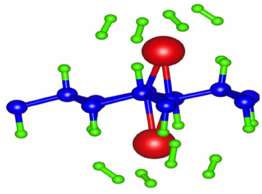
In 2009, Zhou et al predicted a semihydrogenated derivative of graphene which they called graphone.80 Their work stems from the fact that while zigzag edges are able to induce magnetism in graphene sheets, they are less energetically favorable than armchair edges. However, armchair edged graphene sheets do not exhibit magnetism. Therefore, it was proposed that tunable hydrogenation of graphene would induce magnetism.
Using first principles DFT calculations employing the generalized gradient approximation88 as described by the Perdew et al89 functional in the VASP,90–92 Zhou and Sun examined the structure of graphone.87
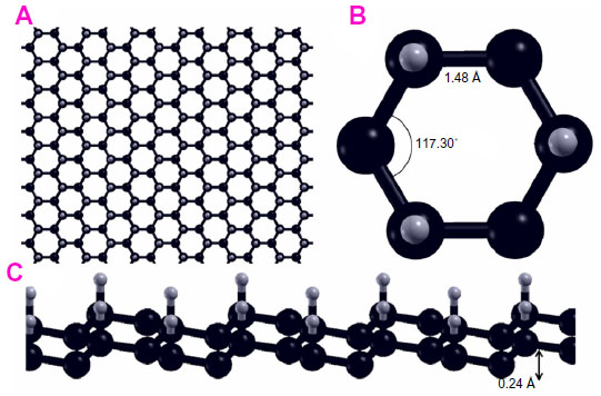
Graphone is a graphene sheet with 50% hydrogenation and stoichiometry C2H. Additionally, the hydrogen atoms are only on one side of the carbon sheet, resulting in a mixture of hybridized sp2 and sp3 carbon atoms. Upon geometry relaxation, it was found that graphone has a somewhat zigzag shape as can be seen in Figure 9. Zhou and Sun87 found that the carbon-carbon bond increased slightly from that of graphene to 1.495 Å, while the carbon-hydrogen bonds were 1.157 Å in a direction normal to the graphene plane. Furthermore, it was found that the distance between the two planes of carbon atoms within the zigzag shape was 0.322 Å. Furthermore, the stability of graphone was examined through MD simulations. After running 3,000 steps of the MD simulations at room temperature with a time step of 1 femtosecond, the geometry of graphone remained unchanged. This indicates that graphone is a stable structure at room temperature.
 | Figure 9 Geometry of a sheet of graphone. |
Next, the magnetism of the graphone sheet was examined.87 It was stated that when half of the carbon atoms are hydrogenated, strong σ bonds are formed between the carbon and hydrogen atoms. These σ bonds not only disrupt the usual π bonding network of graphene that leads to the metallic and nonmagnetic two-dimensional sheet, but also causes the electrons on the carbon atoms not bonded to hydrogen to become localized and unpaired. To study the magnetism of graphone, three magnetic configurations were considered: ferromagnetic (FM), antiferromagnetic (AF), and nonmagnetic states. It was found that the FM state was the ground state with a magnetic moment of about 1 μB on the unhydrogenated carbon atoms. This FM state was 0.15 eV lower in energy than the AF and 0.49 eV lower in energy than the nonmagnetic states for the supercell considered. Furthermore, mean field theory was used to estimate the Curie temperature of the magnetic graphone sheet, which was found to be 278 K when graphone was treated as three-dimensional and 417 K when treated as two-dimensional.
Another study by Boukhvalov83 examines the properties of stable AF graphone, as shown in Figure 10. Using DFT, Boukhvalov argues that although the energy barrier for removal of hydrogen is high enough to make graphone stable, migration of the hydrogen atoms is in fact favorable with an energy barrier less than 0.1 eV, and thus hydrogen based graphone is unsuitable for use in devices. Instead, Boukhvalov suggests fluorinated graphone. Structurally, replacing hydrogen with fluorine has little effect on the graphone sheet, where the carbon bond lengths and out of plane distortions are comparable to hydrogenated graphone. However, the bond length between carbon and the fluorine atoms is larger than that of the carbon and hydrogen bonds, with a C–F bond length of 1.456 Å. The electronic nature, however, is dramatically changed. Fluorine shows markedly different activation and migration energies compared to hydrogen. Removal of one adatom of hydrogen has a barrier of 1.15 eV, while removal of fluorine has a barrier of 1.43 eV. Removal of the second adatom for hydrogen is in fact favorable where the removal of a second fluorine atom has a barrier of 0.50 eV. The migration barrier of fluorine is also much higher than that of hydrogen, with a barrier of 0.72 eV. Examining the density of states of both the hydrogenated and the fluorinated graphone, hydrogen shows two sharp peaks near the Fermi level which corresponds to the unpaired electrons from the nonfunctionalized carbon atoms. When hydrogen is replaced by fluorine, strong hybridization occurs between carbon and the fluorine two p-orbitals which results in a smearing of the localized bands that correspond to unpaired electrons.
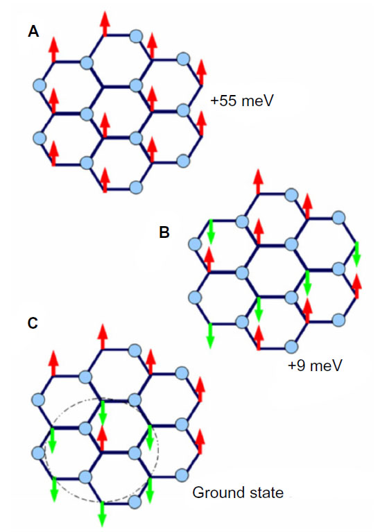 | Figure 10 Comparison of ferromagnetic and antiferromagnetic graphone. |
The magnetic states of the fluorinated graphone were also examined.83 Unlike hydrogenated graphone, the FM state of fluorinated graphone was found to be energetically unfavorable. Instead, the AF state was found to be the more stable configuration by 55 meV. Furthermore, although the specific number was not reported, Boukhvalov83 mentions that there is an opening of the energy gap in the AF fluorinated graphone.
Synthesis
Despite the promising properties of graphone, it still has yet to be synthesized easily. Zhou and Sun87 have proposed a potential strategy by applying pressure to a boron and nitrogen sheet that is on a fully hydrogenated graphene sheet substrate. It was argued that because a fully hydrogenated graphene sheet and a boron and nitrogen sheet have already been synthesized and that the lattice mismatch between the two is small, and that the bonding between fluorine and nitrogen sites in the BN sheet is weak, fluorine atoms introduced to the BN sheet will bind with the boron. Because the nitrogen atoms contain unpaired electrons, they will be reactive. By applying pressure to the hydrogenated graphene and the BN sheets, the nitrogen will pick up the hydrogen from graphene that is between the two sheets. When the pressure is released, the resulting graphene sheet is now only semihydrogenated, with all hydrogen atoms on one side of the sheet. To verify this idea, Zhou and Sun87 performed a series of DFT calculations, which will be detailed in the following paragraphs.
Using the computational software VASP,90–92 Zhou and Sun87 studied different stacking patterns, which they label as trans for boat and cis for chair configurations, in which the difference between the two is a 30° rotation along the z axis. They defined a notation where if the hydrogen atoms on the hydrogenated graphene point toward boron (or nitrogen) atoms of the BN sheet, then they append B (or N) to the notation. For example, if the hydrogen atoms were pointed toward boron, then the system that consisted of the hydrogenated graphene with the fluorinated BN sheet would be donated as G2+F-BN(B). If the hydrogen atoms point toward a hollow site, then nothing would be appended. After performing geometry relaxations, they found that G2+F-BN(N) is the system with the lowest energy, with both trans and cis having degenerate energies. Furthermore, they found the equilibrium distance between the two sheets to be d=6.40 Å, defined as the distance between the fluorine and the hydrogen atoms. It was found that the distance between the two sheets was too large for hydrogen to move from graphene to the BN sheet, despite the bond energy between nitrogen and hydrogen in the F-BN sheet of 4.701 eV, while the bond energy between carbon and hydrogen in the graphene sheet was 4.466 eV. In order for the hydrogen atoms to transition from graphene to the BN sheet, pressure must be applied. As pressure is applied, they found that the G2+F-BN(N) configuration remains energetically favorable, and that the difference between this and the other configurations increases. When the applied pressure causes the two sheets to be within 5.90 Å of each other, the hydrogen atoms moved from the graphene sheet to the BN sheet, forming what they call the trans-G1+F-BN-H(N) configuration. It was noted that the cis form also behaves in a similar manner. This new system was found to be about one eV per supercell more stable than the initial systems, which they attributed to the fact that each N–H bond is more stable than the C–H bond by about 0.235 eV, and that there are four such bonds per supercell.
Applications
FETs
Despite the current difficulties in synthesizing graphone, the applications for graphone make the effort worth pursuing. In a study by Fiori et al,93 graphane, which is a completely hydrogenated form of graphene that will be discussed in the Graphane section, and graphone were examined as a possible material for FETs. They argued that the operation and performance of functionalized graphene-based devices has not been studied to a sufficient degree. Thus, their study focused on these topics in which they performed a multiscale approach using data obtained from GW approximations performed in VASP90–92 for the energy dispersion relations, fitting the computed energy bands to a three-nearest neighbor sp3 tight binding Hamiltonian, and then fed it into a semiclassical model based on ballistic transport to determine the transport properties.
Their modeled system was a double gate device using graphane or graphone and SiO2. Taking the distance of the top and bottom layers of SiO2 as 1 nm away from graphone and a drain-to-source voltage of VDS=VDD=0.8 V, they examined the n-type metal oxide semiconductor and p-type metal oxide semiconductor FETs. From Figure 11, it can be seen that all the devices considered are able to provide large currents, and that the graphone p-type metal oxide semiconductor had the highest quantum capacitance. Furthermore, they found that all devices considered had a high on–off ratio, as can be seen in Figure 12. This study shows some of the promising potential applications for graphone devices.
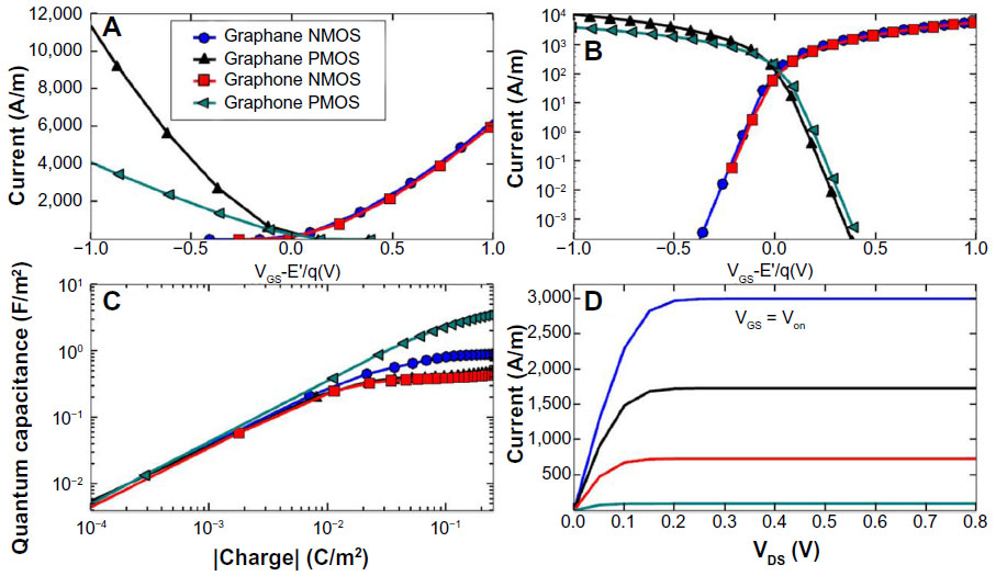 | Figure 11 Transfer characteristics of graphane and graphone. |
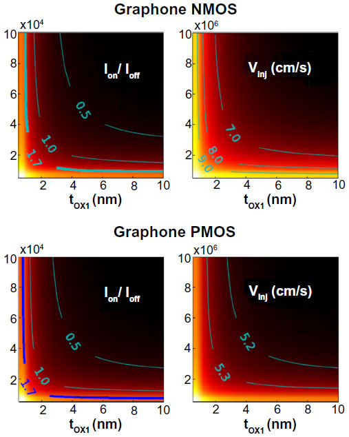 | Figure 12 Color map of Ion/Ioff ratios and injection velocity for graphane and graphone devices as a function of tOX1. |
Organic ferroelectrics
Graphone also has applications in situations that require organic ferroelectrics,81 which have gained considerable interest as organic ferroelectrics are light, flexible, and nontoxic. In their work, Wu et al81 used DFT to investigate the effects of replacing the hydrogen atoms on graphone with OH molecules. They found that the stacking of the hydroxylized graphone, which is denoted as HLGO, results in a spontaneous polarization of 43.7 μC/cm2 along the direction in which the OH molecules point. Furthermore, they found that the system is just as magnetic as graphone, with a magnetic moment of 2.0 μB per unit cell.
In a previous study,94 it was shown that conventional organic ferroelectric materials often face steric hindrance or high energy barriers during switching due to limited intermolecular space. Wu81 argues that using graphone for this type of ferroelectric device is advantageous because: 1) protons in hydrogen-bonded ferroelectrics are free to move due to less spatial constraint; 2) the directional preference of hydrogen bonding allows for a spontaneous polarity to form; and 3) the presence of hydroxyl protons tightly bound to oxygen prevents against thermal agitation which allows for a robust high temperature ferroelectricity. Wu also argues that these hydroxyl decorated systems can serve as ideal cathode materials for use in rechargeable proton batteries. It was shown that even when hydrogen is released from the systems, the structures are still stable. Furthermore, Wu proceeds to calculate specific capacities of these hydroxyl graphene systems to be six times that of the highest theoretical value of the lead acid battery PbO2 and five times that of lithium ion batteries. The appeal to this is that while the lead acid or the lithium ion batteries involve manufacturing methods that require nonrenewable resources, the hydroxyl graphene systems are made of renewable resources.
Molecular packing
In addition to being a component of a device, graphone can also be used to fabricate devices. In a recent study by Reddy et al,95 the effects of a graphone domain embedded within graphene sheets was investigated. Reddy et al examined how patterned graphone domain arrays could serve as a trap for small molecules by means of physisorption. Using atomistic simulations, a large area of graphene was examined, with a side length of 320 Å. This was necessary since the inclusion of the graphone domain will produce distortions that will not be captured with simulations covering a small area. Using the reactive empirical bond order96 and the modified AIREBO version,97 it was found that the circular graphone domain remained planar after a geometry relaxation; however, there were deformations in the out of plane direction that had different morphologies depending on the size of the structure. The largest distortion occurred at the interface between graphene and graphone. Furthermore, three classes of morphologies were defined. The first class appears when the diameter of the graphone is less than 30 Å. This class resembles a bubble on the surface of graphene, where the graphone curves outward in a spherical shape that flattens as the size of the graphone domain increases. For graphone sizes between 30 Å and 130 Å, the second class is defined. In this range, the graphone is highly curved at the interface but then forms either a flat or concave shape. The third class is defined for graphone with a diameter larger than 130 Å. This morphology has sharp curves at the interfaces in both the graphene and graphone; however, the curves between the two point in opposite directions. Toward the center of the graphone domain, the structure is nearly flat. Furthermore, through MD simulations, it was stated that these systems are stable at room temperature and computational results match well with what has been found experimentally.
To demonstrate the viability of molecular packing using graphone domains, C60 molecules were used as an example.95 Calculations were run by placing the C60 molecule above graphone domains of varying size. It was found that for domains less than 15 Å in diameter, there is only one energy minimum whose location is at the center. Depending on the size of the domain, the depth can be between 0.25 eV and 0.65 eV. For graphone domains larger than 15 Å, there were multiple energy minima and they were no longer near the center but instead near the edges of the interface. It was stated that the energy profiles are insensitive to the distances between neighboring graphone domains; however, for a safer design, the distance between two graphone domains should be greater than 20 Å due to possible van der Waals interactions between adjacent molecules. It was claimed that since the energy barriers are larger than the thermal energy at room temperature, the C60 molecule is effectively and stably trapped in the graphone domain. However, at higher temperatures, the C60 molecule is able to escape the trap. Thus, this leads to two types of mechanisms that can lead to release of the packed molecules. First, the molecules can be released by thermal activation, while the second mechanism is through dehydrogenation caused by thermal energy.
Next, the study95 investigates the use of graphone domains as a molecular packing template. Using a square array of graphone domains, C60 molecules were placed within each domain of varying size, which are separated by at least 20 Å to avoid van der Waals interactions between adjacent C60 molecules. It was found that the C60 molecules in the square arrangement of graphone domains behaved in the same manner as the C60 molecule within the isolated graphone domain, even as the domains are increased in size. Expanding the study, the case where multiple C60 molecules are within the same graphone domain was examined. It was found that, for a domain with a 20 Å diameter, three C60 molecules can be placed within the domain. For a domain with a 40 Å diameter, as the C60 molecules were added one at a time, it was found that the molecules first occupied the edges of the graphone domain and then proceeded to fill up the center as more molecules were added. After sufficient molecules were added, they self-assembled into a cluster due to the van der Waals interactions. All situations considered were stable at room temperature. Furthermore, these graphone domains in graphene can act as a template for structures other than C60 molecules. It was claimed that structures such as hydrogen and methanol molecules for energy applications, as well as proteins and DNA for biological applications, can also be stacked in the graphone domains. Hydrogen storage is also a potential application as the height of the out of plane deformation of the graphone domains can be tuned by varying the graphone domain sizes, which then can be used to control the interlayer spacing of the graphene sheets. The packing density can also be modulated by controlling the spacing of the graphone domains.
Graphane
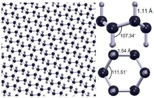
Similar to graphone, graphane is a hydrogenated sheet of graphene, where a primitive graphane cell contains two carbon atoms and two hydrogen atoms.98 The difference in this case is that the graphene sheet is 100% hydrogenated as opposed to 50% hydrogenated. However, the structural parameters are similar. There is roughly a 5° difference in the C—C—C bond angle while there is less than 0.1 Å difference in the C—C bond lengths. As can be seen in Figure 13, the most notable difference is that each carbon in graphane is bound to a single hydrogen atom resulting in complete sp3 hybridization, as opposed to graphone’s mixture of sp2 and sp3 hybridized bonds or graphene’s sp2 hybrid structure. Another difference from previous structures is that at finite temperatures, graphane does not exhibit intrinsic thermal ripples that are present in graphene.99 Furthermore, unlike graphone, graphane has been successfully synthesized, and various studies have been performed on graphane investigating its electronic,100–102 optical,103 mechanical,46,104–108 and thermal109 properties. Graphane is an attractive material due, in part, to the fact that the hydrogenation of graphene into graphane can be reversed through annealing at high temperatures, thus restoring the original properties of graphene.110 The applications for graphane have also been examined in the areas of hydrogen storage,111,112 biosensing,113 transistors,114 and spintronic devices.115
 | Figure 13 Geometry of graphane. |
Properties
Predicted first by Sluiter and Kawazoe116 in 2003 and then by Sofo et al117 in 2007, graphane is a sheet of graphene that has been completely hydrogenated, with one hydrogen atom bound to each carbon atom. As a result, a band gap opens up, even in structures such as graphane nanoribbons (GNRs). The transport properties of these GNRs have been investigated by Zou et al.100 Using VASP,90–92 a series of hybrid graphene-GNRs was examined. Basing their idea on those of Singh and Yakobson41 and Semenoff et al118 who used a “nanoroad” and domain wall embedded in GNRs, Zou et al100 created a hybrid structure formed by substituting zigzag GNRs into zigzag graphene nanoribbons from the middle or edge sides as seen in Figure 14. To investigate the transport properties of the hybrid structures, Zou et al100 used first principles calculations with nonequilibrium Green’s functions.
 | Figure 14 Graphane nanoribbons substituted into graphene nanoribbons. |
It was found that pristine zigzag graphene nanoribbons (ZGNRs) can have their transport properties modulated by the concentration of graphane present in the system as well as the overall stability of the nanoribbons.100 As the width of the substituted GNRs increased, the hybrid systems became more stable. Furthermore, all hybrid systems were found to be more stable than the pure graphene ZGNRs. This conclusion was reached by examining the Gibbs free energy of the hybrid systems. Interestingly, it was found that the most stable of all systems considered were those that had graphane ZGNRs along the edges, as seen in Figure 14B. This indicates that the sp3 hydrogen edge passivation is more favorable than monatomic hydrogen passivation for graphene ZGNRs.
For structures like the one shown in Figure 14A, there is an enhancement of the transmission peak at the Fermi energy compared to graphene nanoribbons, which increases with increasing GNR density. After the density of the GNRs compared to the graphene nanoribbons reaches a certain point, the peak forms into a plateau and eventually splits, forming two distinct platforms on either side of the Fermi energy. This is a result of the GNRs dominating the transport properties. Similar results are also seen for the remaining two configurations of graphone nanoribbons with graphene nanoribbons, although the effects are not as pronounced. The reason behind this observed enhancement of the transmission was shown through examination of the local density of states (LDOS) at the Fermi energy at zero bias of the hybrid systems with varying graphane density.100 It was shown that for pristine graphene ZGNRs, the LDOS concentrates primarily along the edge carbon atoms. However, for a hybrid graphene/graphane system that is comprised of the GNR located between two graphene nanoribbons, the LDOS existed along not only the edge carbon atoms, but also along the interfacial carbon atoms adjacent to the substituted graphane region. Furthermore, the LDOS in this area increased as the width of the GNRs increased. It was noted, however, that in systems where the graphene ZGNRs on either side of the GNR are not equivalent in size, the LDOS distributes only along the edge with the wider graphene nanoribbon. This resulted in a decrease in effective transport channels thus causing a reduction in transport enhancement.
Graphane also provides interesting optical properties when cut into nanoribbons. In work performed by Yang et al103 using first principles calculations through the Cambridge Serial Total Energy Package (CASTEP) software,119 it was found that opposed to graphene nanoribbons, the dielectric function spectra of GNRs are independent of the ribbon edge shapes and widths. Furthermore, it was found that a moderate anisotropy with respect to the type of light polarization exists.
In Yang’s work, the chair conformation of graphane was examined as this is believed to be the most stable configuration.49,103,117 It was first discussed that unlike graphene nanoribbons, GNRs exhibit similar electronic properties between ribbons of different sizes and edge states. This was argued through examination of the band gaps of GNRs and comparing between armchair and zigzag edges. It was then hypothesized that these similar electronic properties may lead to similar optical properties. By calculating the dynamic imaginary dielectric function ε2(ω), which can be seen in Figures 15 and 16, it was found that the armchair and zigzag GNRs exhibit similar shapes and peak positions. Yang points out that because the imaginary dielectric function is zero in the band gap area independent of the orientation and polarization direction, GNRs have no direct transition from the valence band maximum to the conduction band minimum. Yang explains that for parallel polarized light, the imaginary spectra show peaks at around 9.8 eV and 11.7 eV and results from the transition of carbon 2p and hydrogen 1s orbitals to hydrogen 1s and carbon 2p orbitals. On the other hand, for perpendicularly polarized light, peaks appear at around 6.8 eV and 13.2 eV. The 6.8 eV peak is a result of the transition of hydrogen 1s and carbon 2p orbitals to hydrogen 1s orbitals, while the 13.2 eV peak is a result from the transition of carbon 2s, carbon 2p, and hydrogen 1s orbitals to hydrogen 1s orbitals. The slight differences in the energy positions of the peaks may be due to the slight difference in conduction bands. These findings are independent of the edge shapes for both parallel and perpendicular light polarization. Furthermore, since the spectra for the parallel and perpendicular light polarizations are different, it was concluded that graphane and GNRs exhibit optical anisotropy.
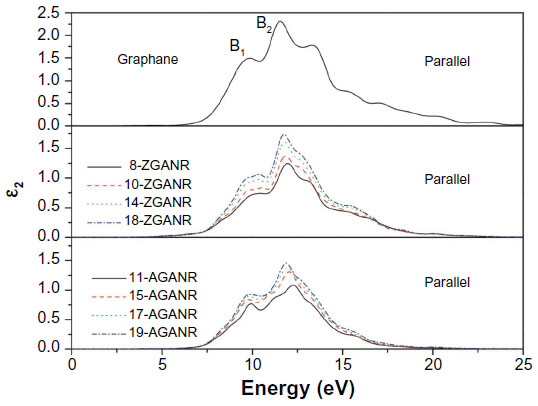 | Figure 15 Imaginary portion of the dielectric function for two-dimensional graphane: parallel polarization. |
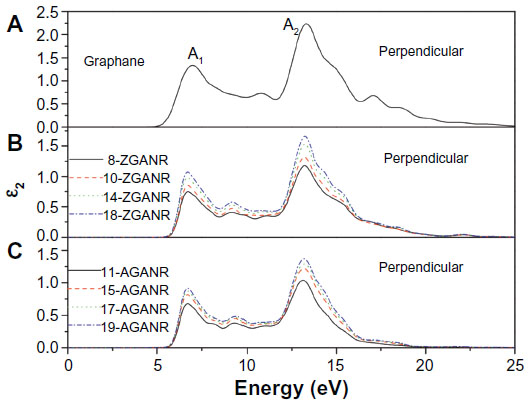 | Figure 16 Imaginary portion of the dielectric function for two-dimensional graphane: perpendicular polarization. |
In addition to interesting optical properties, graphane has interesting mechanical attributes. In a study performed by Peng et al,104 the mechanical response of graphane under various amounts of strain was examined using a continuum model that was fit to results from DFT as implemented in VASP90–92 with104 and without120 van der Waals interactions. It was found that under strain, graphane exhibits anisotropic deformation along the armchair, zigzag, and biaxial directions, indicating an anharmonicity in graphane structures.
As can be seen in Figure 17, the critical strain for graphane, which is the point of maximum strain before rupture, is 0.22 which is less than that of graphene’s at 0.31. Additionally, the ultimate stress and strain was examined for graphane and compared with graphene.104 The ultimate stress and the corresponding ultimate strain is the maximum stress or strain that a system can withstand while being stretched. It was reported that under ideal conditions, the critical strain is larger than the ultimate strain. Graphene and graphane beyond the ultimate strains are in a metastable state, which can then be easily destroyed by long wavelength perturbations, vacancy defects, and high temperature effects.46 The ultimate strain should be considered since it acts as a lower limit of the critical strain. It was found that both graphene and graphane behave in an asymmetric manner with respect to compressive and tensile strains.104 It was found that graphane’s ultimate strength in the armchair, zigzag, and biaxial directions, and the ultimate strain in the armchair direction were less than that of graphene; however, the ultimate strain in the zigzag and biaxial directions were greater and equal to graphene, respectively. This indicates that graphane will rupture before graphene under similar strain. However, through analysis of the elastic constants of both graphene and graphane, it was found that graphane is much softer, with a stiffness of 242 Nm-1, about two thirds that of graphene. Furthermore, to the best of the authors’ knowledge,104 graphane has the smaller Poisson ratio among known monolayer honeycomb structures. This makes graphane a good candidate for materials in building tubes or pipelines for transporting materials at high speed and pressure. This, combined with the reversibility of the hydrogenation of graphane, gives rise to the possibility of high efficiency, high density hydrogen storage.
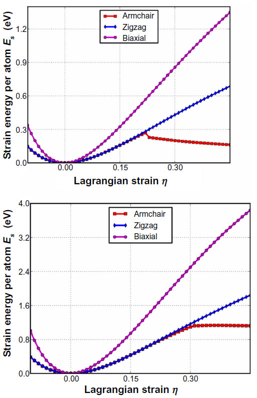 | Figure 17 Energy strain responses for graphane and graphene. |
The electronic properties of graphane have also been investigated. In a study by Chandrachud et al,121 a series of calculations ranging from 0% (graphene) to 100% (graphane) hydrogenated carbon sheets were examined. The goal of the work was to understand the evolution of the electronic structure upon hydrogenation of graphene and gain insight into the way the band gap opens. Using VASP,90–92 it was found that hydrogenation of graphene takes place via clustering of hydrogen atoms. Furthermore, analysis of the density of states indicated that before the gap opens as hydrogenation takes place, the graphene sheet transitions to a metallic character where this metallic state is spatially inhomogeneous, and then to an insulator. The metallic state consists of insulating regions of hydrogenated carbon atoms surrounded by hydrogen free carbon atom channels. By selective decoration of hydrogen atoms, it is possible to tune the electronic structure.
Chandrachud et al121 begins by examining the most stable structure of a 20% hydrogenated graphene system in two configurations. It was found that the most stable configuration is when the hydrogen atoms form a compact cluster. When the hydrogen atoms are randomly placed, the system is 0.9 eV per hydrogen atom higher in energy. Expanding to 50% coverage of hydrogen atoms, a series of different configurations was examined to investigate tuning of the electronic structure. In this instance, seven cases of hydrogenation were examined, which were 1) randomly distributed hydrogen atoms, 2) a chain of bare carbon atoms, 3) three separated clusters, 4) a single cluster with zigzag edges at the interface on two sides and a line of bare carbon atoms on a third, 5) a mixture of armchair and zigzag patterns at the interface, 6) an armchair pattern at the interface, and 7) a zigzag pattern at the interface. Consistent with 20% hydrogenation, the most compact 50% hydrogenation configuration was the most stable. Interestingly, however, it was found that the zigzag interface was the most stable of the compact configurations, with armchair being the second most stable, followed by the mixed armchair and zigzag configuration. The stability of the clusters is explained by the fact that the hydrogen atom placed on a bare carbon atom causes the carbon to move up above the plane by 0.33 Å which deforms the surrounding area. As a result, hydrogen atoms placed further away from the cluster require more energy than ones being placed adjacent to the cluster, thus hydrogenation of graphene to graphane occurs via clustering of hydrogen atoms. This is supported by another study.122 By examining the density of states of the hydrogenated graphene systems from 0% to 100%, it was found that the systems transitioned from graphene like, to metallic with a density of states peaking around 3.5 eV at about 50% hydrogenation, to an insulator at hydrogen concentrations beyond 80% as can be seen in Figure 18.121
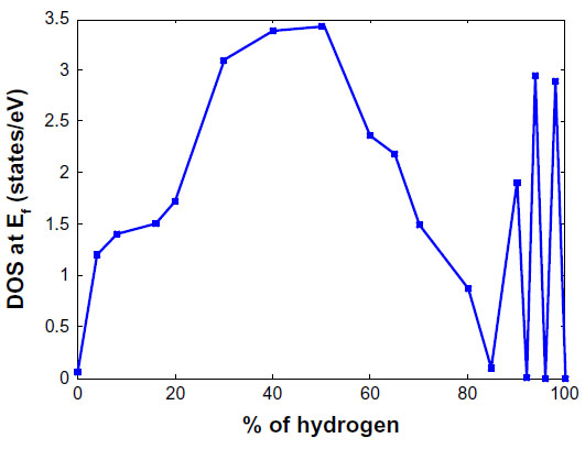 | Figure 18 Variation of the DOS at the Fermi level as a function of hydrogen coverage in graphene. |
Chandrachud et al121 explains that the contribution at the Fermi energy is from the pz orbitals of the bare carbon atoms. As the concentration of hydrogen atoms is increased, there are fewer and fewer bare carbon atoms available for the formation of delocalized π bonds. As a result, the value of the density of states at the Fermi energy approaches zero and a gap opens up, resulting in an insulating system. The oscillating character of the density of states beyond 80% hydrogen concentration is described as graphane with defects by the removal of a few hydrogen atoms which give rise to midgap states. Furthermore, the nature of the metallic states is explained through examination of the electron localization function. It was shown that a charge density exists only along the portions of the hydrogenated graphene systems that do not contain hydrogen atoms. As a result, for systems with around 50% hydrogenation and clustered groups of hydrogen atoms, conducting channels form on the bare carbon atoms while no charge density exists in the insulating regions.
Another aspect of graphane is its thermal properties. In a study by Neek-Amal and Peeters,109 the thermal properties of suspended graphane were examined and compared with the results found for graphene determined through MD simulations. Investigating a graphane sheet with dimensions 183 Å × 185 Å and a graphene sheet with dimensions 170 Å × 170 Å to consider both zigzag and armchair directions, the authors performed their investigation at nonzero temperatures above 50 K. By allowing the systems to relax during the first 5 picoseconds, it was found that both the graphane and graphene lattices shrink through surface corrugation. They found that at thermal equilibrium, graphene’s length is longer than that of graphane, which indicates that graphane’s surface is much more corrugated than graphene. This is attributed to the larger amplitude of the ripples in graphane when compared to graphene due to the hydrogen atoms above and below the carbon sheet which pushes them in different directions. They also found that despite graphane being thicker than graphene, and thus having a positive or at least smaller thermal contraction with respect to graphene, graphane has larger negative thermal contraction. Furthermore, at temperatures above 1,500 K, a buckling of graphane was observed.
Next, Neek-Amal and Peeters109 examined the roughness of the graphane and graphene sheets. It was found that the average square root out of plane deviation of the carbon atoms for graphane was 1.3 Å, 6.5 times larger than graphene’s deviation of 0.2 Å. The authors then proceeded to estimate the roughness exponent χ of graphane, which is obtained from the second order structure function S(δ).123 It was found that S(δ) for graphane was almost an order of magnitude larger than that of graphene, which indicates larger corrugation. By examining the slope of S(δ), χ can be determined. They found that below room temperature, graphene has a larger χ value, indicating that graphene is smoother than graphane. However, at higher temperatures, both systems approach χ~1. Furthermore, it was found that by examining the total energies of the systems as the temperature is varied, the heat capacity can be obtained. For graphene, the heat capacity was found to be 24.98 J/mol · K which compares well with another study,124 while the heat capacity for graphane was found to be 29.32 J/mol · K.
Aside from the boat-type graphane already synthesized in experiments, Wen et al theoretically predicted eight isomeric two-dimensional graphane sheets.125 Four of these nets – two built on chair cyclohexanes and two on boat – are thermodynamically more stable than the isomeric benzene or polyacetylene, as shown in Figure 19. Under high pressure, there are phase transitions among these isomeric graphane sheets, indicating that high pressure may offer a novel way to synthesize other graphane isomers.
 | Figure 19 Graphane sheets and crystals. |
Synthesis
Unlike graphone, graphane has been successfully synthesized. In an experimental study by Elias et al,40 graphane was synthesized for the first time by first annealing graphene crystals at 300°C in an argon atmosphere for 4 hours to remove any contaminants. Afterward, the samples were exposed to cold hydrogen plasma. Using a low pressure hydrogen argon mixture with samples 30 cm away from the discharge zone, the samples were treated for a time period of typically 2 hours. Before treatment with atomic hydrogen, the samples exhibited weak temperature dependence of their resistivity at all gate voltages, with a metallic dependence observed close to the neutrality point below 50 K and half-integer quantum Hall effect at cryogenic temperatures, which are indications that the samples were indeed graphene. However, this behavior changed after treatment with atomic hydrogen. The samples exhibited an insulating behavior where the resistivity grew by two orders of magnitude with decreasing temperature. Carrier mobility decreased at liquid helium temperatures and the quantum Hall plateaus completely disappeared. Furthermore, the neutrality point gate voltages shifted by around 50 V. These samples were stable at room temperature for many days and showed the same characteristics during repeated measurements. It was also found that by annealing the hydrogenated samples at 450°C in an argon atmosphere for 1 day, the samples returned to graphene. This provides excellent evidence for the creation and control of hydrogenated graphene for use in devices.
Additional experimental investigations have been performed in an effort to convert graphene to graphane. In a study by Poh et al,126 a scalable method for hydrogenation of graphene was presented that was based on thermal exfoliation of graphite oxide in a hydrogen atmosphere at high pressure and temperature. What is interesting about this method is that it does not require a plasma source and is able to produce gram quantities of graphane, thus it has the potential for mass production of graphane. The investigation was carried out using three different sets of reaction conditions. The first set had the temperature held constant at about 220°C as the hydrogen gas pressure was varied between 60 and 150 bar during the exfoliation process. For the second set, the hydrogen gas pressure was held constant at 100 bar while the temperature during exfoliation was varied from 200°C to 500°C. The third set was a control, where graphene was exfoliated in an inert argon gas atmosphere, and was used as a comparison with the other two sets. Since the initial material used was graphite oxide, scanning electron microscopy images of the control and hydrogenated graphene samples were taken. The resulting images gave a clear indication that the graphite oxide was successfully exfoliated and that no observable differences between the control and the hydrogenated graphene samples were present. Furthermore, transmission electron microscopy was used to examine single to few layer sheets of the resulting materials. Aside from wrinkling of some hydrogenated graphene structures exfoliated at high temperatures, no observable differences existed between the control and the hydrogenated graphene samples. Thus, the scanning and transmission electron microscopy results provide evidence that the exfoliation process is able to confirm the effective exfoliation of graphite oxide.
To determine the quality of the resulting hydrogenated graphene samples, the density of defects was investigated using Raman spectroscopy.126 The Raman spectroscopy data revealed two distinct peaks, one at 1,300 cm−1 and another at 1,590 cm−1. The first peak corresponds to a defect in the sp2 lattice (D peak) and the other to the sp2 hybridized carbon (G peak). The ratio between the D and G is a good indicator of the quality on bulk samples. If both bands have similar intensity this indicates a high quantity of structural defects. The D/G ratio increases from 0.85 to 1.10 as the exfoliation gas pressure increases from 60 bar to 150 bar at a constant temperature of 220°C. This is attributed to the increasing amount of defects introduced when higher hydrogen gas pressures were used during the exfoliation process. Figure 20 shows the results for when the pressure is held constant at 100 bar while the temperature is varied from 200°C to 500°C. As the exfoliation temperature increases, it was found that the D/G ratio decreases from 0.87 at 200°C to 0.77 at 350°C. The difference between the graphene that was exfoliated in hydrogen gas and the graphene that was exfoliated in argon was attributed to the partial hydrogenation of graphene that may have occurred.
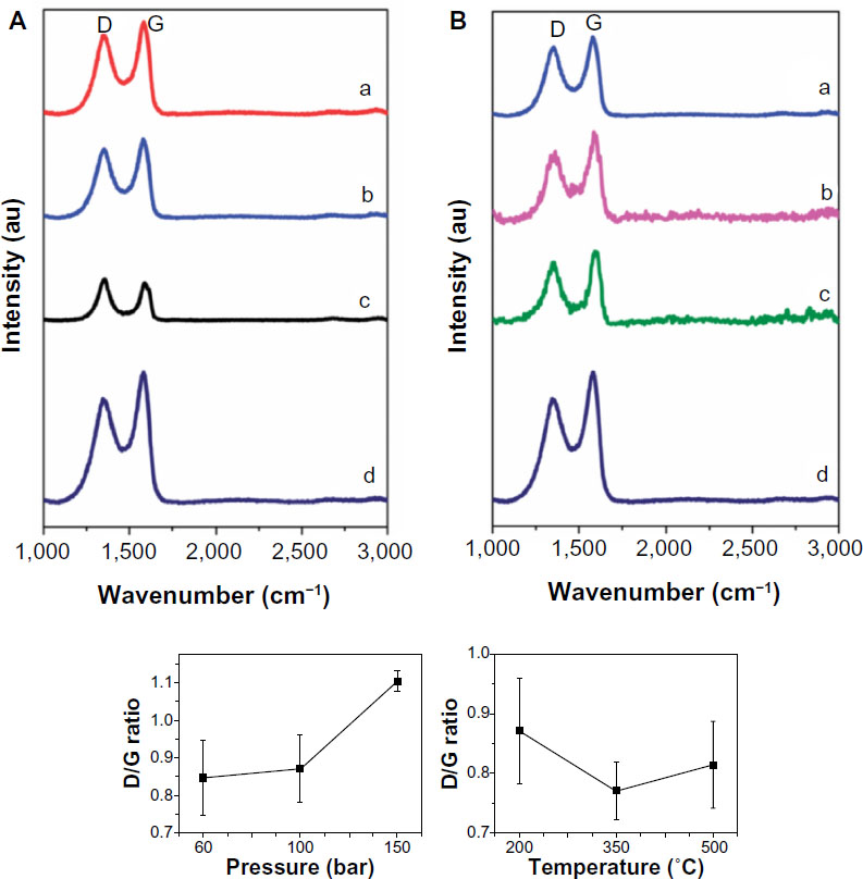 | Figure 20 Raman spectra of hydrogenated graphenes. |
To investigate the hydrogenation efficiency of the materials, the X-ray photoelectron spectroscopy (XPS) technique was used.126 By using a wide scan XPS measurement, the amount of oxygen-containing groups present after exfoliation/hydrogenation was measured. It was found that for a fixed temperature of 220°C, higher pressures of hydrogen gas contained far more oxygen groups than at lower pressures. On the other hand, with the pressure held constant at 100 bar, the amount of oxygen groups present at 200°C decreased greatly at 500°C. This indicates that to more easily remove the oxygen groups during exfoliation/hydrogenation, lower pressures of hydrogen gas combined with higher temperatures must be employed. However, while the XPS method is useful in determining the type of chemical bonds present, its effectiveness in determining the degree of hydrogenation is limited due to the small difference between single and double bonded carbon atoms in terms of bonding energy. To make this distinction, the authors126 claim that the best approach is to conduct a combustion elemental analysis. At the beginning of the study, the authors were aware that the graphite oxides contained 50.64% carbon, 20.82% hydrogen, and 28.54% oxygen. Combining this data with results from Fourier transform infrared spectroscopy, it was concluded that all of the hydrogen atoms in the graphene oxides were bonded to the oxygen atoms present in the starting material. Investigating the graphene exfoliated under high pressure and temperature in the hydrogen gas atmosphere, it was found that the composition consisted of 80.55% carbon, 11.6% hydrogen, and 7.84% oxygen. From the previous analysis of the graphite oxide,126 where the hydrogen atoms were all bound to oxygen, it can be deduced that the remaining 3.76% hydrogen was bound directly to the carbon backbone to give graphane. For graphene exfoliated in a nonhydrogen atmosphere, it was found that there was a lack of hydrogenation of graphene. Thus, through the methods presented by the authors,126 large quantities of graphane may be synthesized by using a hydrogen gas pressure of 100 bar at 500°C. This development may prove useful in future device synthesis.
Applications
With the varying properties of graphane examined, there are a number of application possibilities present, of which a few will be discussed here, such as hydrogen storage, biosensing, and spintronics.
Hydrogen storage
We begin with the application of graphane for uses in hydrogen storage. In a study by Hussain et al,111 DFT and MD simulations as implemented in VASP90–92 were used to examine the stability, electronic structure, and hydrogen storage capacity of strain-induced stabilization of lithium doped graphane. Two symmetries, hexagonal and rectangular, in the dispersion of lithium on graphane were examined and their relative stabilities were compared. Furthermore, the effects of lithium stabilization on the enhancement of hydrogen storage capacity of lithium doped graphane were discussed.
For their choice of the supercell, Hussain et al111 replaced two hydrogen atoms with lithium, resulting in a doping concentration of 25%. Upon geometry optimizations of the system, the two lithium atoms centered above the bond between two carbon atoms as seen in Figure 21. It was found that, without strain, the hexagonal cell binding energy for lithium was 1.755 eV, while for the rectangular cell, the binding energy was 2.231 eV, which indicates that the dispersion of lithium in the rectangular symmetry on graphane is more energetically favorable. With strain, it was found that the binding energy of lithium increased when compared to the case without strain. For the hexagonal cell, the maximum binding energy of lithium with graphane was found to be 2.401 eV with a biaxial strain of 7.5% in the x direction and 10.0% in the y direction, a value 38% higher than in the zero strain case. For the rectangular case, the maximum binding energy was the same as the biaxial strain; however, the effect was less pronounced at 2.48 eV. The authors claimed that this increase in binding energy is an indication of the stability of lithium on the graphane monolayer at higher temperatures and doping concentrations. Continuing with their study, the authors performed MD simulations using the Nose-thermostat algorithm at 400 K with a 1 femtosecond time step on the lithium doped graphene system. It was found that the structure remained intact even after 3 picoseconds, indicating the stability of the system. Furthermore, investigating the impact of the lithium dopant, it was found that the band gap of graphane disappeared, and the system now had a metallic character. Examination of the partial density of states indicates that there is strong hybridization between the lithium atom and the carbon atom to which lithium is covalently bonded, and that the bands near the Fermi energy are due to the lithium dopant.
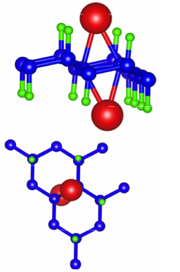 | Figure 21 Side and top view of optimized graphane with two lithium dopants. |
To investigate the adsorption of hydrogen on the lithium doped graphane system, first the rectangular system was examined.111 Beginning with the adsorption of hydrogen on the system without strain, hydrogen molecules were introduced to both lithium atoms on opposite sides of the graphane sheet in a stepwise manner. Through a charge analysis, it was found that the lithium atoms possess a positive charge. This charge polarizes the hydrogen molecules which are then held to the lithium ions by van der Waal’s forces. In the case of zero strain, it was found that at most, three hydrogen molecules can be adsorbed on each lithium atom. This results in a storage capacity of 9.37 wt%. However, in the case of the applied strain that produces the highest lithium binding energy, the number of hydrogen molecules that can bind to lithium increases to four per lithium atom, as seen in Figure 22. This increases the hydrogen storage capacity to 12.12 wt%, which is well beyond the Department of Energy (DOE) target until 2017. Furthermore, the binding energies of the adsorbed hydrogen molecules are consistently between 0.15 eV and 0.20 eV, regardless of how many hydrogen molecules are adsorbed. This study provides a potential application of graphane for hydrogen storage using lithium dopants.
 | Figure 22 Optimized structure of lithium doped graphane with maximum amount of H2 coverage. |
Biosensing
Another possible application of graphane is for use in biosensing. In experimental work by Tan et al,113 the properties of graphane were compared with graphene for use in electrochemical oxidation of biomarkers by using a ferro/ferricyanide probe via cyclic voltammetry and electrochemical impedance spectroscopy.127 The use of graphane in biosensing could be a novel use for carbon based devices in biotechnological applications.
To perform their electrochemical measurements,113 the synthesized graphene and hydrogenated graphene structures were dispersed in dimethylformamide by sonication. After sonication, the aliquot of the suspension was placed onto a glassy carbon electrode that had been previously polished. The deposited material was then allowed to dry. This process was repeated three times to form three layers of a coating. Afterward, the system was dipped into an electrochemical cell with an electrolyte solution before starting the electrochemical measurements.
As can be seen in Figure 23, Tan et al113 found that there were varying peak intensities and positions between the three examined biomarkers, which were ascorbic acid, dopamine, and uric acid. However, in all cases examined, the hydrogenated graphene system, or graphane, was able to provide a detection peak with lower electric potential than both the glassy carbon and graphene surfaces. This could possibly allow for less harmful ways for detection of biomarkers, resulting in experiments that allow for a greater viability of the examined cells. It should be pointed out, however, that these results were not compared with other methods such as current techniques used in biosensing, and thus the effectiveness of using graphane as a biosensor is left unanswered. However, this study still provides an interesting look into uses for graphane other than in electronic device applications.
 | Figure 23 Hydrogenated graphene surfaces. |
Spintronics
Although by no means a complete list of applications for graphane, a final aspect we examine is its spintronic device applications. In a study by Da et al,115 a number of different transition metals were embedded within graphane. This transition metal atom replaces both the carbon atom that would normally be in that position as well as the bound hydrogen. The result of these embedded transition metal atoms is that there are varying amounts of net magnetization within the systems studied. Furthermore, it was shown that by designing a heterojunction structure with nickel and vanadium embedded within graphane, the spin current can be effectively manipulated. As a result, one spin current, which in this work has been deemed the spin down current, can be completely suppressed when a negative bias voltage is applied, resulting in a perfect spin filter and spin current diode. This study provides an exciting look into the effective manipulation of spin currents in device applications.
Using VASP,90–92 Da et al115 begin their investigation by optimizing the graphane structures with the embedded transition metals. It was found that the original configuration of graphane remains intact, with the only difference being the metal atoms moved out of the plane due to their larger sizes, which induced a local curvature that the authors labeled “h”. Interestingly, when examining embedded zinc, it was found that there was a positive binding energy, indicating that there is a repulsion between graphane and the zinc atom. As the various transition metal embedded systems were examined, the authors took note of the band gaps, both for spin up and spin down. Interestingly, with the exception of scandium and cobalt, all transition metals examined exhibited spin splitting between the spin up and spin down channels.
After a detailed discussion about the effects of various transition metal atoms, including the induced magnetic moments as a function of simulation cell size, Da et al115 begin to discuss the possible applications of the nickel/vanadium-embedded graphane for use in spintronic devices, as can be seen in the inset in Figure 24A. The transport properties of the system were investigated using a fully self-consistent nonequilibrium Green’s function method combined with DFT as implemented in the Atomistix ToolKit.128–130 The results of their transport calculations can be seen in Figure 24A. From the figure, it can be seen that the spin down current vanishes for both positive and negative bias. The authors attribute this to the zero density of states around the Fermi level in both the nickel and vanadium graphane structures. For both positive and negative bias voltages, the spin down current is completely suppressed in the system. However, for a positive bias voltage, the spin up current increases slightly and then is completely suppressed, while with a negative bias, the spin current increases monotonically. This provides a possible spin current diode application. To help understand the physical insights of the transport behavior of the spin up electrons, the authors examined the density of states of the nickel/vanadium embedded graphane and plotted the transmission spectra for a few select voltages, which can be seen in Figure 24B. It can be seen that, on the left part of Figure 24B, with a negative bias voltage, the density of states of the embedded atoms overlap which enhances the transmission. However, examining the right side of the figure shows that with positive bias voltage, the density of states of the two atoms move apart, resulting in a lack of transmission. This provides an excellent description of the behavior of a spin current diode and also shows high spin filter efficiency. The authors comment, however, that there are other processes that exist when the systems are exposed to a hydrogen plasma environment, and that these processes may alter the electronic and magnetic properties and thus change the transport functions of the materials, but that was outside the current scope of their study.
 | Figure 24 Transition metal atom embedded graphane. |
Conclusion and outlook
In summary, we have reviewed the mechanical, physical, and chemical properties, and the applications in nanotechnology of four new two-dimensional materials: graphyne, graphdiyne, graphone, and graphane. Studies of graphyne and its family of materials, including graphdiyne, have uncovered some useful properties. The different bonding structures of graphyne-1 and the changes in electronic properties of the n-graphynes give a rich set of properties, even in the pristine state, and the introduction of vacancies, adsorbed atoms, external electric fields, and mechanical strains provide ample means to modify these properties, most importantly the band gap. Graphyne has not yet been synthesized in large quantities, although research is continuing, and will be needed to provide experimental data against which to test the computational predictions as well as to clarify some discrepancies regarding mechanical properties. Still, the predicted electronic properties of graphyne show great promise for use in transistor electronics as well as optoelectronics. Its nonzero band gap combined with high charge carrier mobility are very desirable characteristics for high speed switching applications with large on–off ratios. In addition, the electromechanical coupling exhibited by graphyne is useful in many sensing applications.
Graphdiyne, despite having mechanical properties inferior to graphyne and graphene, has several useful electronic properties, some of which have been verified experimentally following successful synthesis in 2010.75 Graphdiyne is a semiconductor where the electrons behave as though they were massless, both in theory and experimentally, promising to break one of the fundamental limits of silicon based transistors, the electron speed. This opens up new possibilities for many electronic devices, particularly FETs, because of the electromagnetic properties also exhibited by finite sheets of graphdiyne. Graphyne and graphdiyne also present many opportunities for modification through doping with a variety of methods including adsorption and substitution of other structures such as BN into the lattice.
We have examined the properties of graphone, from its first prediction in 200980 where its stability at room temperature and magnetic properties were examined. It was seen that graphone is able to provide a stable net magnetic moment at room temperature without the necessity to engineer different edge states which thus aids in reducing the difficulty in manufacturing magnetic carbon based structures. Unfortunately, a reliable method for synthesizing graphone is yet to be found, although we have examined one possible method which involves applying pressure to a BN sheet that resides on top of a graphane substrate. By applying pressure, the nitrogen of the BN sheet pulls the hydrogen atoms off graphane, thus stripping one size of the graphane sheet and becoming graphone. However, despite the difficulty in synthesizing graphone, its possible applications make it a worthwhile endeavor. Graphone was shown to have promising applications for FETs with a high on–off ratio. Additionally, by replacing the hydrogen atoms with OH molecules, graphone may be used in organic ferroelectrics. The advantage of using graphone in this manner is that there is less spatial confinement for the protons in the system, the directional preference of hydrogen in these systems allows for a spontaneous polarization to form, and that the presence of the hydroxyl protons bound to oxygen prevents against thermal agitation, thus allowing for robust high temperature ferroelectricity. Furthermore, graphone may be used for molecular packing. Small domain arrays of graphone can be used to trap small molecules by means of physisorption. These domains can then be used as packing templates for structures such as C60 molecules. Overall, despite the current difficulty in synthesizing graphone, graphone remains a promising structure for use in a variety of devices.
We have also examined graphane in our review. We have seen that when graphane is used to form nanoroads of graphene structures, there are interesting transport properties present. These nanoroads enhance transmission peaks around the Fermi energy. It can also be seen that there is a concentration of the density of states right at the graphene/graphane junction. Furthermore, GNRs also allow for interesting optical properties. We have seen that, as opposed to graphene nanoribbons, the dielectric function spectra of GNRs are independent of the ribbon edge shapes and widths. Additionally, there was anisotropy with respect to the light polarization. The mechanical properties of graphane were also reviewed. Through a DFT study,104 it was seen that graphane is softer than pure graphene, and that graphane cannot be distorted as much as graphene before rupture. However, the increased flexibility of graphane gives rise to possible high efficiency, high density hydrogen storage.
In addition to the optical and mechanical properties of graphane, we have also reviewed the electronic and thermal aspects. In an attempt to understand the evolution of the electronic structure of graphene as the hydrogenation process goes from 0% (graphene) to 100% (graphane), it was found that clusters of hydrogen atoms form on graphane. This was determined by the fact that the most stable configuration of the systems during the hydrogenation process was when the hydrogen atoms formed tight clusters, and that the addition of more hydrogen atoms occurred more easily at the boundaries of the hydrogen clusters rather than further away. As for the thermal properties of graphane, the rippling behavior and heat capacity were reviewed. It was found that as temperature increases, graphane becomes more rippled, while the heat capacity was seen as 29.32 J/mol K, which is slightly higher than that of graphene.
We have also reviewed how graphane is synthesized. Unlike graphone, graphane has been successfully synthesized using a couple of different methods. The first creation of graphane was through hydrogen plasma; however, this method allows for relatively smaller samples of graphane. On the other hand, it may be possible to synthesize large amounts of graphane through thermal exfoliation that does not require a plasma source.
Some of the applications of graphane have been reviewed. It has promising applications for hydrogen storage, where we have seen that by using lithium dopant atoms, graphane has the possibility of being used as a high density hydrogen storage device. We have seen that the binding energies of hydrogen molecules to the lithium dopant are independent of how many hydrogen molecules are present, and that there is a high density of these molecules per lithium atom. Another application for graphane reviewed was its use in biosensing. It was seen that graphane allows for the sensing of the tested molecules at a lower electrochemical potential than that of graphene or glassy carbon. Furthermore, we have reviewed the use of graphane in spintronic devices. We have seen that by doping graphane with different transition metals, graphane can act as a spin current diode. These are just some of the possible applications in which graphane can be used.
Acknowledgments
The authors would like to acknowledge the generous financial support from the Defense Threat Reduction Agency (DTRA) Grant # BRBAA08-C-2-0130 and # HDTRA1-13-1-0025.
Disclosure
The authors declare no conflicts of interest in this work.
References
Diederich F, Kivala M. All-carbon scaffolds by rational design. Adv Mater. 2010;22:803–812. | |
Hirsch A. The era of carbon allotropes. Nat Mater. 2010;9:868–871. | |
Geim AK, Novoselov KS. The rise of graphene. Nat Mater. 2007;6:183–191. | |
Novoselov KS, Fal’ko VI, Colombo L, Gellert PR, Schwab MG, Kim K. A roadmap for grapheme. Nature. 2012;490:192–200. | |
Kroto HW, Heath JR, O’Brien SC, Curl RF, Smalley RE. C60:Buckminsterfullerene. Nature. 1985;318:162–163. | |
Iijima S. Helical microtubules of graphitic carbon. Nature. 1991;354: 56–58. | |
Kong XY, Ding Y, Yang R, Wang ZL. Single-crystal nanorings formed by epitaxial self-coiling of polar nanobelts. Science. 2004;303:1348–1351. | |
Nasibulin AG, Pikhitsa PV, Jiang H, et al. A novel hybrid carbon material. Nat Nanotechnol. 2007;2:156–161. | |
Novoselov KS, Geim AK, Morozov SV, et al. Electric field effect in atomically thin carbon films. Science. 2004;306:666–669. | |
Malko D, Neiss C, Viñes F, Görling A. Competition for graphene: graphynes with direction-dependent dirac cones. Phys Rev Lett. 2012;108:086804. | |
Novoselov KS, Geim AK, Morozov SV, et al. Two-dimensional gas of massless Dirac fermions in grapheme. Nature. 2005;438:197–200. | |
Lee C, Wei X, Kysar JW, Hone J. Measurement of the elastic properties and intrinsic strength of monolayer grapheme. Science. 2008;321:385–388. | |
Lin YM, Jenkins KA, Valdes-Garcia A, Small JP, Farmer DB, Avouris P. Operation of graphene transistors at gigahertz frequencies. Nano Lett. 2009;9:422–426. | |
Lin YM, Dimitrakopoulos C, Jenkins KA, et al. 100-GHz transistors from wafer-scale epitaxial graphene. Science. 2010;327:662. | |
Liao L, Lin YC, Bao M, et al. High-speed graphene transistors with a self-aligned nanowire gate. Nature. 2010;467:305–308. | |
Peng Q, Crean J, Dearden AK, et al. Defect engineering of 2d monatomic-layer materials. Mod Phys Lett B. 2013;27:1330017. | |
Xu M, Liang T, Shi M, Chen H. Graphene-like two-dimensional materials. Chem Rev. 2013;113:3766–3798. | |
Peng Q, Ji W, De S. Mechanical properties of the hexagonal boron nitride monolayer: ab initio study. Comput Mater Sci. 2012;56:11–17. | |
Peng Q, De S. Tunable band gaps of mono-layer hexagonal BNC heterostructures. Physica E. 2012;44:1662–1666. | |
Peng Q, Zamiri AR, Ji W, De S. Elastic properties of hybrid graphene/boron nitride monolayer. Acta Mech. 2012;223:2591–2596. | |
Peng Q, Ji W, De S. First-principles study of the effects of mechanical strains on the radiation hardness of hexagonal boron nitride monolayers. Nanoscale. 2013;5:695–703. | |
Peng Q, Chen XJ, Ji W, De S. Chemically tuning mechanics of graphene by BN. Adv Eng Mater. 2013;15:718–727. | |
Peng Q, Liang C, Ji W, De S. A first principles investigation of the mechanical properties of g-TlN. Model Numer Simul Mater Sci. 2012;2:76–84. | |
Peng Q, Liang C, Ji W, De S. A first principles investigation of the mechanical properties of g-ZnO: the graphene-like hexagonal zinc oxide monolayer. Comput Mater Sci. 2013;68:320–324. | |
Peng Q, Chen XJ, Liu S, De S. Mechanical stabilities and properties of graphene-like aluminum nitride predicted from first-principles calculations. RSC Adv. 2013;3:7083–7092. | |
Peng Q, Liang C, Ji W, De S. A first-principles study of the mechanical properties of g-GeC. Mech Mater. 2013;64:135–141. | |
Peng Q, Liang C, Ji W, De S. Mechanical properties of g-GaN: a first principles study. Appl Phys A. 2013;13:483–490. | |
Peng Q, Wen X, De S. Mechanical stabilities of silicone. RSC Adv. 2013;3:13772–13781. | |
Kara A, Enriquez H, Seitsonen AP, et al. A review on silicene – new candidate for electronics. Surf Sci Rep. 2012;67:1–18. | |
Jose D, Datta A. Structures and chemical properties of silicene: unlike graphene. Acc Chem Res. Epub November 12, 2013. | |
Peng Q, De S. Outstanding mechanical properties of monolayer MoS2 and its application in elastic energy storage. Phys Chem Chem Phys. 2013;15:19427–19437. | |
Peng Q, De S. Mechanical properties and instabilities of ordered graphene oxide C6O monolayer. RSC Adv. 2013;3:24337–24344. | |
Narita N, Nagai S, Suzuki S, Nakao K. Optimized geometries and electronic structures of graphyne and its family. Phys Rev B. 1998;58:11009–11014. | |
Kang J, Li J, Wu F, Li SS, Xia JB. Elastic, electronic, and optical properties of two-dimensional graphyne sheet. J Phys Chem C. 2011;115: 20466–20470. | |
Srinivasu K, Ghosh SK. Graphyne and graphdiyne: promising materials for nanoelectronics and energy storage applications. J Phys Chem C. 2012;116:5951–5956. | |
Novoselov KS, Jiang D, Schedin F, et al. Two-dimensional atomic crystals. Proc Natl Acad Sci U S A. 2005;102:10451–10453. | |
Ma Y, Dai Y, Guo M, Huang B. Graphene-diamond interface: gap opening and electronic spin injection. Phys Rev B. 2012;85:235448. | |
Brumfiel G. Graphene gets ready for the big time. Nature. 2009;458:390–391. | |
Kaloni TP, Cheng YC, Schwingenschloegl U. Electronic structure of superlattices of graphene and hexagonal boron nitride. J Mater Chem. 2012;22:919–922. | |
Elias DC, Nair RR, Mohiuddin TM, et al. Control of graphene’s properties by reversible hydrogenation: evidence for graphane. Science. 2009;323:610–613. | |
Singh AK, Yakobson BI. Electronics and magnetism of patterned graphene nanoroads. Nano Lett. 2009;9:1540–1543. | |
Balog R, Jorgensen B, Nilsson L, et al. Bandgap opening in graphene induced by patterned hydrogen adsorption. Nat Mater. 2010;9:315–319. | |
Ma Y, Dai Y, Guo M, Niu C, Zhang Z, Huang B. Electronic and magnetic properties of the two-dimensional C4H-type polymer with strain effects, intrinsic defects and foreign atom substitutions. Phys Chem Chem Phys. 2012;14:3651–3658. | |
Burgess JS, Matis BR, Robinson JT, et al. Tuning the electronic properties of graphene by hydrogenation in a plasma enhanced chemical vapor deposition reactor. Carbon. 2011;49:4420–4426. | |
Castellanos-Gomez A, Wojtaszek M, Arramel, Tombros N, van Wees BJ. Reversible hydrogenation and bandgap opening of graphene and graphite surfaces probed by scanning tunneling spectroscopy. Small. 2012;8:1607–1613. | |
Topsakal M, Cahangirov S, Ciraci S. The response of mechanical and electronic properties of graphane to the elastic strain. Appl Phys Lett. 2010;96:091912. | |
Pei QX, Sha ZD, Zhang YW. A theoretical analysis of the thermal conductivity of hydrogenated graphene. Carbon. 2011;49:4752–4759. | |
Dillon AC, Heben MJ. Hydrogen storage using carbon adsorbents: past, present and future. Appl Phys A. 2001;72:133–142. | |
Sahin H, Ataca C, Ciraci S. Magnetization of graphane by dehydrogenation. Appl Phys Lett. 2009;95:222510. | |
Xie L, Wang X, Lu J, et al. Room temperature ferromagnetism in partially hydrogenated epitaxial grapheme. Appl Phys Lett. 2011;98:193113. | |
Sessi P, Guest JR, Bode M, Guisinger NP. Patterning graphene at the nanometer scale via hydrogen desorption. Nano Lett. 2009;9:4343–4347. | |
Baughman RH, Eckhardt H, Kertesz M. Structure-property predictions for new planar forms of carbon-layered phases containing sp2 and sp atoms. J Chem Phys. 1987;87:6687. | |
Coluci VR, Braga SF, Legoas SB, Galvão DS, Baughman RH. Families of carbon nanotubes: graphyne-based nanotubes. Phys Rev B. 2003;68:035430. | |
Baughman RH, Galvao DS, Cui CX, Wang Y, Tomanek D. Fullereneynes: a new family of porous fullerenes. Chem Phys Lett. 1993;204:8–14. | |
Diederich F. Carbon scaffolding: building acetylenic all-carbon and carbon-rich compounds. Nature. 1994;369:199–207. | |
Bunz UH, Rubin Y, Tobe Y. Polyethynylated cyclic pi-systems: scaffoldings for novel two and three-dimensional carbon networks. Chem Soc Rev. 1999;28:107–119. | |
Balaban AT, Rentia CC, Ciupitu E. Chemical graphs 6. Estimation of relative stability of several planar and tridimensional lattices for elementary carbon. Rev Roum Chim. 1968;13:231. | |
Peng Q, Wei J, De S. Mechanical properties of graphyne monolayer: a first-principles study. Phys Chem Chem Phys. 2012;14:13385–13391. | |
Cranford SW, Buehler MJ. Mechanical properties of graphyne. Carbon. 2011;49:4111–4121. | |
Zhang YY, Pei QX, Wang CM. Mechanical properties of graphynes under tension: a molecular dynamics study. Appl Phys Lett. 2012;101:081909. | |
Duin Adri CT, Dasgupta S, Lorant F, Goddard W. J Phys Chem A. 2001;105:9396–9409. | |
Pan LD, Zhang LZ, Song BQ, Du SX, Gao HJ. Graphyne- and graphdiyne-based nanoribbons: density functional theory calculations of electronic structures. Appl Phys Lett. 2011;98:173102. | |
He J, Ma SY, Zhou P, Zhang CX, He C, Sun LZ. Magnetic properties of single transition-metal atom absorbed graphdiyne and graphyne sheet from DFT + U calculations. J Phys Chem C. 2012;116:26313–26321. | |
Gholami M, Melin F, Mcdonald R, Ferguson MJ, Echegoyen L, Tykwinski RR. Synthesis and characterization of expanded radialenes, bisradialenes, and radiaannulenes. Angew Chem Int Ed Engl. 2007;46:9081–9085. | |
Haley MM. Synthesis and properties of annulenic subunits of graphyne and graphdiyne nanoarchitectures. Pure Appl Chem. 2008;80:519–532. | |
Kim KS, Zhao Y, Jang H, et al. Large-scale pattern growth of graphene films for stretchable transparent electrodes. Nature. 2009;457:706–710. | |
Postel SL, Daily GC, Ehrlich PR. Human appropriation of renewable fresh water. Science. 1996;271:785. | |
Xue M, Qiu H, Guo W. Exceptionally fast water desalination at complete salt rejection by pristine graphyne monolayers. Nanotechnology. 2013;24:505720. | |
Cranford SW, Buehler MJ. Selective hydrogen purification through graphdiyne under ambient temperature and pressure. Nanoscale. 2012;4:4587–4593. | |
Ivanovskii AL. Graphynes and graphdyines. Prog Solid State Chem. 2013;41:1–19. | |
Haley MM, Brand SC, Pak JJ. Carbon networks based on dehydrobenzoannulenes: synthesis of graphdiyne substructures. Angew Chem Int Ed Engl. 1997;36:836–838. | |
Pei Y. Mechanical properties of graphdiyne sheet. Physica B. 2012;407: 4436–4439. | |
Cui HJ, Sheng XL, Yan QB, Zheng QR, Su G. Strain-induced dirac cone-like electronic structures and semiconductor-semimetal transition in graphdiyne. Phys Chem Chem Phys. 2013;15:8179–8185. | |
Kang J, Wu F, Li J. Modulating the bandgaps of graphdiyne nanoribbons by transverse electric fields. J Phys Condens Matter. 2012;24:165301. | |
Li G, Li Y, Liu H, Guo Y, Li Y, Zhu D. Architecture of graphdiyne nanoscale films. Chem Commun. 2010;46:3256–3258. | |
Bu H, Zhao M, Zhang H, Wang X, Xi Y, Wang Z. Isoelectronic doping of graphdiyne with boron and nitrogen: stable configurations and band gap modification. J Phys Chem B. 2012;116:3934–3939. | |
Balog R, Jorgensen B, Nilsson L, et al. Bandgap opening in graphene induced by patterned hydrogen adsorption. Nat Mater. 2010;9:315–319. | |
Haberer D, Vyalikh DV, Taioli S, et al. Tunable band gap in hydrogenated quasi-free-standing graphene. Nano Lett. 2010;10:3360–3366. | |
Kharche N, Nayak SK. Quasiparticle band gap engineering of graphene and graphone on hexagonal boron nitride substrate. Nano Lett. 2011;11:5274–5278. | |
Zhou J, Wang Q, Sun Q, Chen XS, Kawazoe Y, Jena P. Ferromagnetism in semihydrogenated graphene sheet. Nano Lett. 2009;9:3867–3870. | |
Wu M, Burton JD, Tsybal EY, Zheng XC, Jena P. Hydroxyl-decorated graphene systems as candidates for organic metal-free ferroelectrics, multiferroics, and high-performance proton battery cathode materials. Phys Rev B. 2013;87:081406. | |
Feng L, Zhang WX. The structure and magnetism of graphone. AIP Advances. 2012;2:042138. | |
Boukhvalov DW. Stable antiferromagnetic graphone. Physica E. 2010;43:199–201. | |
Gmitra M, Kochan D, Fabian J. Spin-orbit coupling in hydrogenated grapheme. Phys Rev Lett. 2013;110:246602. | |
Pujari BS, Gusarov S, Brett M, Kovalenko A. Single-side-hydrogenated graphene: density functional theory predictions. Phys Rev B. 2011;84:041402. | |
Podlivaev AI, Openov LA. On the thermal stability of graphone. Semiconductors. 2011;45:958–961. | |
Zhou J, Sun Q. How to fabricate a semihydrogenated graphene sheet? A promising strategy explored. Appl Phys Lett. 2012;101:073114. | |
Perdew J, Burke K, Ernzerhof M. Generalized gradient approximation made simple. Phys Rev Lett. 1996;77:3865–3868. | |
Perdew JP, Burke K, Ernzerhof M. ERRATA:Generalized gradient approximation made simple. Phys Rev Lett. 1997;78:1396. | |
Kresse G, Furthmuller J. Efficiency of ab-initio total energy calculations for metals and semiconductors using a plane-wave basis set. Comput Mater Sci. 1996;6:15–50. | |
Kresse G, Hafner J. Ab initio molecular dynamics for liquid metals. Phys Rev B. 1993;47:558–561. | |
Kresse G, Furthmüller J. Efficient iterative schemes for ab initio total-energy calculations using a plane-wave basis set. Phys Rev B. 1996;54:11169–11186. | |
Fiori G, Lebegue S, Betti A, et al. Simulation of hydrogenated graphene field-effect transistors through a multiscale approach. Phys Rev B. 2010;82:153404. | |
Horiuchi S, Kumai R, Tokura Y. Hydrogen-bonding molecular chains for high-temperature ferroelectricity. Adv Mater. 2011;23:2098–2103. | |
Reddy CD, Zhang YW, Shenoy VB. Patterned graphone? A novel template for molecular packing. Nanotechnology. 2012;23:165303. | |
Brenner DW, Shenderova OA, Harrison JA, Stuart SJ, Ni B, Sinnot SB. A second-generation reactive empirical bond order (REBO) potential energy expression for hydrocarbons. J Phys Condens Matter. 2002;14: 783–802. | |
Stuart S, Tutein A, Harrison J. A reactive potential for hydrocarbons with intermolecular interactions. J Chem Phys. 2000;112:6472–6486. | |
Sahin H, Ataca C, Ciraci S. Electronic and magnetic properties of graphane nanoribbons. Phys Rev B. 2010;81:205417. | |
Costamagna S, Neek-Amal M, Los JH, Peeters FM. Thermal rippling behavior of graphane. Phys Rev B. 2012;86:041408. | |
Zou W, Yu Z, Zhang CX, Zhong JX, Sun LZ. Transport properties of hybrid graphene/graphane nanoribbons. Appl Phys Lett. 2012;100:103109. | |
Sahin H, Ataca C, Ciraci S. Electronic and magnetic properties of graphane nanoribbons. Phys Rev B. 2010;81:205417. | |
Cudazzo P, Tokatly IV, Rubio A. Dielectric screening in two-dimensional insulators: implications for excitonic and impurity states in grapheme. Phys Rev B. 2011;84:085406. | |
Yang YE, Yang YR, Yan XH. Universal optical properties of graphane nanoribbons: a first-principles study. Physica E. 2012;44:1406–1409. | |
Peng Q, Liang C, Ji W, De S. A theoretical analysis of the effect of the hydrogenation of graphene to graphane on its mechanical properties. Phys Chem Chem Phys. 2013;15:2003–2011. | |
Cadelano E, Palla PL, Giordano S, Colombo L. Elastic properties of hydrogenated grapheme. Phys Rev B. 2010;82:235414. | |
Cadelano E, Colombo L. Effect of hydrogen coverage on the Young’s modulus of grapheme. Phys Rev B. 2012;85:245434. | |
Leenaerts O, Peelaers H, Hernández-Nieves AD, Partoens B, Peeters FM. First-principles investigation of graphene fluoride and graphane. Phys Rev B. 2010;82:195436. | |
Munoz E, Singh AK, Ribas MA, Penev ES, Yakobson BI. The ultimate diamond slab: graphAne versus graphEne. Diamond and Related Materials. 2010;19:368–373. | |
Neek-Amal M, Peeters FM. Lattice thermal properties of graphane: thermal contraction, roughness, and heat capacity. Phys Rev B. 2011;83:235437. | |
Lu YH, Feng YP. Band-gap engineering with hybrid graphane-graphene nanoribbons. J Phys Chem C. 2009;113:20841–20844. | |
Hussain T, Sarkar AD, Ahuja R. Strain induced lithium functionalized graphane as a high capacity hydrogen storage material. Appl Phys Lett. 2012;101:103907. | |
Pujari BS, Kanhere DG. Density functional investigations of defect-induced mid-gap states in graphane. J Phys Chem C. 2009;113:21063–21067. | |
Tan SM, Sofer Z, Pumera M. Biomarkers detection on hydrogenated graphene surfaces: towards applications of graphane in biosensing. Electroanalysis. 2013;25:703–705. | |
Huang L, Zheng Z. Patterning graphene nanostripes in substrate-supported functionalized graphene: a promising route to integrated, robust, and superior transistors. Front Phys. 2012;7:324–327. | |
Da H, Feng YP, Liang G. Transition-metal-atom-embedded graphane and its spintronic device applications. J Phys Chem C. 2011;115:22701. | |
Sluiter MH, Kawazoe Y. Cluster expansion method for adsorption: application to hydrogen chemisorption on grapheme. Phys Rev B. 2003;68:085410. | |
Sofo JO, Chaudhari AS, Barber GD. Graphane: a two-dimensional hydrocarbon. Phys Rev B. 2007;75:153401. | |
Semenoff GW, Semenoff V, Zhou F. Domain walls in gapped grapheme. Phys Rev Lett. 2008;101:087204. | |
Segall MD, Lindan PJ, Probert MJ, et al. First-principles simulation: ideas, illustrations and the CASTEP code. J Phys Condens Matter. 2002;14:2717. | |
Peng Q, Chen Z, De S. A density functional theory study of the mechanical properties of graphane with van der Waals corrections. Mech Adv Mater Struc. 2013; DOI:10.1080/15376494.2013.839067 | |
Chandrachud P, Pujari BS, Haldar S, Sanyal B, Kanhere DG. A systematic study of electronic structure from graphene to graphane. J Phys Condens Matter. 2010;22:11. | |
Hornekær L, Rauls E, Xu W, et al. Clustering of chemisorbed H(D) atoms on the graphite (0001) surface due to preferential sticking. Phys Rev Lett. 2006;97:186102. | |
Neek-Amal M, Asgari R, Rahimi Tabar MR. The formation of atomic nanoclusters on graphene sheets. Nanotechnology. 2009;20:135602. | |
Zakharchenko KV, Katsnelson MI, Fasolino A. Finite temperature lattice properties of graphene beyond the quasiharmonic approximation. Phys Rev Lett. 2009;102:046808. | |
Wen XD, Hand L, Labet V, et al. Graphane sheets and crystals under pressure. Proc Natl Acad Sci U S A. 2011;108:6833–6837. | |
Poh HL, Sanek F, Sofer Z, Pumera M. High-pressure hydrogenation of graphene: towards graphane. Nanoscale. 2012;4:7006–7011. | |
Poh HL, Sofer Z, Pumera M. Graphane electrochemistry: electron transfer at hydrogenated graphenes. Electrochem Commun. 2012;25:58–61. | |
Brandbyge M, Mozos JL, Ordejon P, Taylor J, Stokbro K. Density-functional method for nonequilibrium electron transport. Phys Rev B. 2002;65:165401. | |
Soler JM, Artacho E, Gale JD, et al. The SIESTA method for ab initio order-N materials simulation. J Phys Condens Matter. 2002;14:2745–2779. | |
Taylor J, Guo H, Wang J. Ab initio modeling of quantum transport properties of molecular electronic devices. Phys Rev B. 2001;63:245407. |
 © 2014 The Author(s). This work is published and licensed by Dove Medical Press Limited. The
full terms of this license are available at https://www.dovepress.com/terms
and incorporate the Creative Commons Attribution
- Non Commercial (unported, 3.0) License.
By accessing the work you hereby accept the Terms. Non-commercial uses of the work are permitted
without any further permission from Dove Medical Press Limited, provided the work is properly
attributed. For permission for commercial use of this work, please see paragraphs 4.2 and 5 of our Terms.
© 2014 The Author(s). This work is published and licensed by Dove Medical Press Limited. The
full terms of this license are available at https://www.dovepress.com/terms
and incorporate the Creative Commons Attribution
- Non Commercial (unported, 3.0) License.
By accessing the work you hereby accept the Terms. Non-commercial uses of the work are permitted
without any further permission from Dove Medical Press Limited, provided the work is properly
attributed. For permission for commercial use of this work, please see paragraphs 4.2 and 5 of our Terms.