Back to Archived Journals » Reports in Medical Imaging » Volume 7
Magnetic resonance imaging of metal artifact reduction sequences in the assessment of metal-on-metal hip prostheses
Authors Aboelmagd S, Malcolm P, Toms A
Received 12 February 2014
Accepted for publication 13 March 2014
Published 21 May 2014 Volume 2014:7 Pages 65—74
DOI https://doi.org/10.2147/RMI.S40052
Checked for plagiarism Yes
Review by Single anonymous peer review
Peer reviewer comments 2
Sharief M Aboelmagd, Paul N Malcolm, Andoni P Toms
Department of Radiology, Norfolk and Norwich University Hospital National Health Service Trust, Norwich, UK
Abstract: Recent developments in metal artifact reduction techniques in magnetic resonance (MR) have, in large part, been stimulated by the advent of soft tissue complications associated with modern metal-on-metal total hip replacements. Metallic orthopedic implants can result in severe degradation of MR images because ferromagnetic susceptibility causes signal loss, signal pile-up, geometric distortion, and failure of fat suppression. There are several approaches to controlling these susceptibility artifacts. Standard fast spin echo sequences can be adapted by modifying echo times, matrix, receiver bandwidth, slice thickness, and echo trains to minimize frequency encoding misregistration. Short tau inversion recovery and 2-point Dixon techniques are both more resistant to susceptibility artifacts than spectral fat suppression. A number of dedicated metal artifact reduction sequences are now available commercially. The common approach of these multispectral techniques is to generate three dimensional datasets from which the final images are reconstructed. Frequency encoding misregistration is controlled using a variety of techniques, including specific resonant frequency acquisition, view-angle tilting, and phase encoding. Metal artifact reduction MR imaging has been the key to understanding the prevalence, severity, and prognosis of adverse reactions to metal debris in metal-on-metal hip replacements. Conventional radiographs are typically normal or demonstrate minimal change and are unable to demonstrate the often extensive soft tissue abnormalities, which include necrosis, soft tissue masses and fluid collections, myositis, muscle atrophy, tendon avulsions, and osteonecrosis. These MR findings correlate poorly with clinical and serological measures of disease, and therefore MR imaging is the principal tool for the diagnosis of soft tissue disease and surveillance in metal-on-metal hip replacements.
Keywords: MRI, artifact, hip, arthroplasty, soft tissue
Introduction
Total hip replacements (THRs) are probably the commonest cause of metal artifact in cross-sectional imaging. In pelvic computed tomography (CT) and magnetic resonance (MR), they have long been an incidental nuisance in which the artifact can usually be ameliorated by simple measures and a diagnostic study achieved. Over the past 10 years or so, there has been a rapid increase in interest in cross-sectional imaging of the bone and soft tissues adjacent to the THR itself.1 This has largely been driven by the adverse reaction to metal debris (ARMD) associated with modern metal-on-metal (MOM) THRs that were first implanted in the mid- to late 1990s. Until then, the mainstay of THR surveillance had been the plain radiograph, which is satisfactory for monitoring the more common mechanisms of failure in metal-on-polyethylene (MOP) THRs such as osteolysis and cement failure. In contrast, the ARMD seen in MOM THRs is often rapid and predominantly affects soft tissues in the immediate periprosthetic environment. The plain radiographs are either normal or woefully underrepresent the extent of the disease.2 Metal artifact reduction (MAR) MR imaging has been key to the identification,3–6 staging,7,8 surveillance,9 and management of this disease. The demand for MAR MR imaging has stimulated a systematic approach to protocol optimization and the development of advanced artifact reduction sequences. MAR MR is now being used to investigate other diseases of THRs, such as infection, and the principles are routinely applied to other metal implants.
The aim of this article is to describe how metal artifacts are generated on MR, how they can be controlled by adjusting standard parameters in conventional sequences, and how some of the more advanced MAR techniques work and their application in clinical practice.
Metal artifact
Metal artifact consists of four main effects: signal loss, signal pile-up, geometric distortion, and failure of fat suppression. Signal loss produces a drop in the signal-to-noise ratio (SNR), and therefore a noisy image, and when severe, it results in signal voids. Signal pile-up manifests as a curvilinear hyperintense signal that typically follows the contour of the prosthesis and lies adjacent to an area of signal void. Geometric distortion causes warping of the normal periprosthetic anatomy. All of these effects are worse with higher field strength, ferromagnetic alloys rather than titanium, and spherical rather than linear prostheses.10,11
Magnetic susceptibility
The source of these artifacts is the difference in magnetic susceptibility between the metal implant and the surrounding soft tissues. The magnetic susceptibility of a material is a constant (Χ) that describes how magnetized (M) a material becomes within a given magnetic field (H), where M= ΧH.12 The magnetic susceptibility χ of water is negative, which means that the internal magnetic field M of water is reduced compared with the external magnetic field H. This is a property of diamagnetic materials. If Χ is positive, then the magnetic field within the material is strengthened (a feature of paramagnetic materials). Ferromagnetic materials also have a positive magnetic susceptibility and, in addition, remain positively magnetized even after they have been removed from a magnetic field. The relationship between M and H is not linear, with the result that the differences in magnetization (in other words, the difference in strength of the magnetic field between the THR and the surrounding soft tissues) are large. This large difference occurs over a small distance, and so the rate of change of magnetization from one anatomical location to the next is rapid. The change from one anatomical location to a second point creates a localized magnetic field gradient, and it is this that disrupts the homogeneity of the external magnetic field. Protons would normally precess at a frequency that is proportional to the strength of the external magnetic field, but close to a prosthesis, with rapid field gradients, the natural precessional frequency is increased (Figure 1).
 | Figure 1 Diagram demonstrating a point or spherical ferromagnetic body placed in a static magnetic field (A), which will become highly magnetized, forming a dipole aligned with the outside field. The field lines of this dipole alternately align with and oppose the outside magnetic field, producing a “four-leaf clover” pattern of susceptibility artifact (B). In-plane frequency misregistration causes alternating bands of signal loss and signal pile-up (C). |
Geometric distortion
To generate an MR image, a single point has to be localized in three dimensions, so it can be assigned to the correct slice and, within a slice, to the correct coordinate along the in-plane axes of the image. A slice select radiofrequency (RF) gradient is applied during the acquisition of the image so that along the slice select direction, protons precess at different frequencies, depending on their position along the gradient. The frequency of the excitation RF pulse is selected to correspond to the precessional frequency of those protons at one point along that gradient, so that in a perfectly homogeneous magnetic field, only a perfectly defined slice of tissue is excited and contributes to the echo from which the image will be constructed.
However, in an inhomogeneous magnetic field, some of the protons within the target slice of tissue will not be precessing at the assumed frequency, and protons at other slice locations will be precessing at the frequency of the excitation pulse. This results in the selected slice being warped and in the final image containing data from adjacent slices. This is known as the through-plane or “potato chip” artifact (Figure 2).
 | Figure 2 Diagrammatic representation of the reconstruction of a stack of magnetic resonance slices that assumes linearity in the two frequency encoding and one phase encoding directions (A). The misregistration resulting from the high field gradients caused by metal bodies causes signal loss, pile-up, and both in-plane and through-plane geometric distortion, producing a “potato chip” artifact (B). |
A frequency encoding gradient is also used to encode the position of signal in one of the orthogonal planes of the slice. Again, this encoding gradient should be linear, but local field gradients can distort it so that it becomes curvilinear, with the result being that the position of the data from a voxel will be misregistered along that axis. This is known as in-plane distortion. Local field gradients do not affect the phase of precession, and so the phase encoding direction is resistant to in-plane geometric distortion.11
Signal void and pile-up
There are three causes of the signal voids on MR imaging of THRs. The first is the prosthesis itself, which generates no signal. The second is dephasing, and the third, and arguably most important, is misregistration along frequency encoding gradients.
When a volume of tissue is excited, the protons absorb the energy of the RF excitation pulse and precess at a given frequency, but also in phase; in other words, the spin of the protons is synchronized. The number of protons spinning in phase is proportional to the signal generated within a voxel. After the RF pulse ceases, the protons become progressively less synchronized (in other words, they dephase), and the signal from the voxel decays. In normal tissues, the echo time is selected to detect this signal before it decays. In an area of tissue in which there is a steep local field gradient, such as close to a ferromagnetic prosthesis, this dephasing occurs very rapidly, much more quickly than standard decay times for neighboring soft tissue, resulting in signal voids on the final MR image.
Misregistration as a result of frequency encoding, both in-plane and through-plane in the slice select directions, is a cause for signal voids in addition to the geometric distortion described earlier. Along a distorted frequency, encoding gradient protons at several positions may precess at the same frequency. This frequency will locate the position of the signal from voxels at different positions to a single point on the final image. The amplitude of the signal of this voxel will correspond to the sum of all the voxels with the same precession frequency, and will therefore inappropriately hyperintense. This is termed “signal pile-up” (Figure 3). The voxels whose signal has been misattributed to another position on the matrix will be represented by pixels with zero or low values and will therefore be hypointense and another cause of a signal void.11
 | Figure 3 Diagrammatic representation of how the frequency encoding direction is more sensitive to susceptibility artifacts than the phase encoding direction (A). High field gradients distort the assumed linearity of the frequency encoding gradient, which means that within a plane, signal is misattributed from one voxel to another (B). This means that one voxel has signal removed, causing a signal void (red voxel), and another has its signal enhanced (white voxel), resulting in signal pile-up or hyperintensities. Frequency gradients are also applied in the slice select direction so that misregistration also occurs between slices. |
Failed fat suppression
Spectral fat suppression is based on the observation that protons precess at different frequencies in different tissues. The peak precessional frequency of protons in fat can be identified in a volume of tissue. This can be used to set the frequency of a saturation RF pulse, which nulls the signal from all protons precessing at that frequency, but this relies on the precessional frequencies of all the tissues remaining constant across the volume of tissue. The magnetic susceptibility of a prosthesis spreads all the peaks of precessional frequencies in the spectrum, making it more difficult to selectively null this signal in a given tissue.11
MAR
There are three main approaches to reducing metal artifact in magnetic resonance imaging (MRI). The first is to influence the interaction of prosthesis with the MR scanner, the second is to adjust conventional MR sequence parameters, and the third is to use advanced MAR MR sequences.
Prosthesis and magnetic field
The relationship between field strength and artifact is straightforward: The stronger the B0 magnetic field, the greater the susceptibility and the greater the artifact. Therefore, the general approach is to use a 1.0–1.5 T field strength, rather 3.0 T. However, the ability to reduce metal artifact also depends on the gradient strengths, and therefore the quality of the final image will also depend on other specifications of the MR scanner. It is possible to get good MAR at 3.0 T if the frequency encoding gradient is sufficiently steep.
All metallic implants will result in susceptibility artifact, but the steel ferromagnetic alloys are significantly worse than the paramagnetic alloys of titanium. Metal artifact associated with titanium prostheses can be almost completely eliminated.
The shape and orientation of the prosthesis also has a strong influence on the severity of the artifact. Predominantly linear structures arranged parallel to the B0 magnetic field, such as the stem of the femoral component of a THR, result in the least artifact. Large spherical components, such as a resurfacing arthroplasty, produce the worst artifact. Spherical or point sources of ferromagnetic susceptibility produce a characteristic four-leaf clover signal void, as the field induced by the metal alternately suppresses or enhances the local B0 field.
180° refocusing pulses
Fast spin echo (FSE), or turbo spin echo, sequences should be the standard for imaging around metal, and gradient echo sequences should be avoided. Spin echo sequences are preferred above gradient echo sequences. FSE sequences include multiple 180° refocusing RF pulses designed to correct dephasing resulting from external magnetic field inhomogeneities, including susceptibility gradients. These inhomogeneities accelerate dephasing of proton spins. Using FSE sequences compensates for most of the signal loss caused by dephasing. Any residual signal loss is a result of frequency misregistration. Gradient echo sequences have no 180° refocusing pulse and use gradient refocusing, which does not correct for external field inhomogeneities, and are therefore severely affected by signal voids caused by dephasing.11
Echo time
FSE sequences with short echo times (in other words, T1 and proton density-weighted sequences) are more resistant to artifact than heavily T2-weighted sequences. The longer the echo time, the more time there is for dephasing; therefore, time to echo (TE) of more than 100 ms should be avoided. In practice, by shortening the TE to 30–40 milliseconds, the resulting intermediate weighting usually provides sufficiently T2-weighted information for diagnostic imaging without noticeable dephasing effects.
Encoding directions
As described earlier, when reading out the echo from a particular slice, it is the frequency encoding direction, rather than the phase encoding direction, that is prone to misregistration artifact. This means that geometric distortion and signal voids predominate in the frequency encoded axis of the final image. Therefore, the phase and frequency encoding directions can be switched in any given image to best demonstrate the periprosthetic soft tissues in the phase encoding direction13,14 (Figure 3).
Voxel size
The volume of susceptibility artifact is directly proportional to the strength of the frequency encoding gradient (GFE), which is itself defined by the following formula.
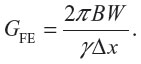
The gyromagnetic ratio (γ) is fixed for a given field strength, but the receiver bandwidth and the voxel size (Δx) can both influence the magnitude of the frequency encoding gradient and, therefore, the metal artifact. The effect of reducing the voxel size is that the variation in phase across the voxel is reduced, which reduces intravoxel dephasing. This can be achieved both in-plane and through-plane by increasing the matrix and reducing the slice thickness. The penalty for doing this is a decrease in SNR, which can be compensated for by increasing the acquisition time, which of course lengthens the examination and the chances of movement artifact (Figure 4).
 | Figure 4 Diagram representing a voxel in which all the protons have the same phase of spin and are considered to be coherent (A), which results in good signal. In the presence of metal, a steep susceptibility field gradient will spread the phases across a voxel (B). The greater the spread of phases, the less coherence between protons there is and the worse the signal. The spread of phases within a voxel can be reduced by reducing the size of the voxel. The proton spin is more coherent, but there are fewer protons to contribute to the signal, which increases noise. Reducing voxel size can be achieved by increasing the matrix or, as in this case, reducing slice thickness. A 6 mm thick slice axial T2 weighted magnetic resonance slice through a right total hip replacement (C) is reduced to a 3 mm thick slice (D) with all other parameters remaining fixed. There is increased conspicuity of the right ischial tuberosity (white arrows) on the thinner slice, but a visible increase in noise. |
In theory, the data from repeated thin slices could be averaged to increase SNR, but the signal rises as an inverse proportion of the number of slices, and therefore, a plateau in SNR is rapidly achieved.15
Receiver bandwidth
Increasing bandwidth is one of the techniques for reducing susceptibility artifacts. Bandwidth can be increased during slice selection (transmitter bandwidth) and readout stages (receiver bandwidth). Increasing receiver bandwidth is an important method used to reduce susceptibility artifacts on FSE sequences. From the equation that defines the strength of the frequency encoding gradient (GFE) described earlier in the Voxel size section, it can be seen that increasing the receiver bandwidth increases GFE and, therefore, decreases susceptibility artifact. The GFE can be visualized as a sloping line drawn between two axes, where the x-axis is position in the magnet and the y-axis is frequency. A proton lying within a local field gradient caused by a hip prosthesis may spin too fast or too slow, and therefore will be misregistered along the x-axis. As the slope of GFE is increased, so the magnitude of misregistration along the x-axis is decreased. The main theoretical limitation to increasing the readout bandwidth is a reduction in SNR. In practice, although this increases the visible noise in the image, it does not usually limit the diagnostic quality.15 Increasing receiver bandwidth also increases power deposition, which may require the use of longer relaxation times or fewer interleaved slices per repetition, and therefore may increase acquisition times (Figure 5).
 | Figure 5 Graph demonstrating how misregistration artifacts can be reduced in the frequency-encoding directions by increasing the receiver bandwidth (A), although this effect plateaus at about 400 Hz/pixel on a 1.5 T system. At 256 Hz/pixel (B), there is the typical susceptibility artifact around the spherical component of a total hip replacement comprising signal loss, pile-up, and geometric distortion (arrow), which is reduced when the receiver bandwidth is increased to 480 Hz/pixel (C) but is accompanied by an increase in noise. The longitudinally oriented femoral stem (arrowheads) produces much less artifact. |
Short tau inversion recovery and 2-point Dixon
Even after employing all the MAR techniques described so far, spectral fat suppression is not suitable for MR imaging near metal. Short tau inversion recovery (STIR) sequences are the mostly widely used for fat suppression in the presence of metal. STIR imaging is based on the difference in T1 relaxation times between fat and water. After a 180° inversion pulse, which inverts the longitudinal magnetization, the 90° pulse which will generate an echo is timed to coincide with the longitudinal magnetisation value reaching zero for fat. The RF pulse therefore generates signal from water only. In other words, STIR does not depend on precessional frequency for suppression and is, therefore, resistant to local field gradients. The limitation of using STIR imaging is that SNR is typically low compared with fat suppression. This is because the longitudinal magnetization of water is attenuated, along with that of fat, during the recovery after the inversion pulse.
Dixon-based MR sequences16 can also be used for fat suppression and typically have better overall SNR than STIR. Dixon methods acquire images when fat and water are in-phase, and again when they are out of phase. From this, a water-only image can be calculated. The Dixon-based techniques make a number of assumptions, including perfect field homogeneity. The sequences can perform well at a distance from THRs, but closer to the prosthesis, this technique tends to fail.11 STIR is probably the better option, although there has been no systematic comparison of the two techniques (Figure 6).
 | Figure 6 Coronal short tau inversion recovery (A), 2-point Dixon (B), and multiacquisition variable resonance image combination proton density weighted fat saturation (C) images of a resurfacing arthroplasty of the right hip at 3 T. The short tau inversion recovery image demonstrates the typical “four-leaf clover” signal voids seen in spherical metal implants. Although the signal-to-noise ratio is better with the 2-point Dixon, the artifact is worse. The multiacquisition variable resonance image combination sequence produces dramatic metal artifact reduction but is limited to a large field of view and blurring of the image. |
The approaches to MAR described so far can all be implemented on standard clinical MR platforms. What follows are more advanced techniques that are either separate commercial packages or are not yet fully implemented into commercial applications.
Off-resonance imaging
One approach to dealing with geometric distortion, and signal loss or pile-up, caused by resonant frequency changes induced by local field gradients from prostheses is off-resonance imaging. Choosing different field strengths for the excitation RF pulse (GEX) and the refocusing RF pulse (GREF) limits the range of resonant frequencies that make up the readout. Large misregistrations are effectively excluded, rather than corrected.17
View-angle tilting
View-angle tilting is a technique described for correcting in-plane displacement artifacts for which differing explanations are given.11 The most common explanation is that during the read-out stage of the pulse sequence, the slice select gradient is replayed. This has the effect of shearing all the frequencies within the plane of the slice. The magnitude of this displacement exactly counteracts the in-plane displacement caused by the metal. This is analogous to being viewed from an angle.18–20 The effect only corrects in-plane, and not through-plane, distortions, and therefore is used in combination with other techniques such as off-resonance imaging and multispectral sequences to correct the through-plane artifact.
Multispectral imaging
Through-plane artifacts can be addressed by using multispectral MR imaging techniques. Multiacquisition variable resonance image combination (MAVRIC) is a method that corrects both through-plane and in-plane artifacts.21 In-plane artifacts are limited by exciting specific frequencies. When this is done in-plane, displacement is limited to one voxel. Instead of selecting slices, which contain a range of resonant frequencies, the images are reconstructed from a three-dimensional dataset populated by multiple acquisitions at a range of frequencies. The problem of through-plane distortion is dealt with by using phase-encoding, instead of encoding with a range of frequencies in the conventional slice-select direction. MAVRIC has been shown to improve visualization of periprosthetic bone, synovium, and regional tendons compared with FSE sequences.22 The limitations of MAVRIC are that sequences are currently limited to a fixed echo time, which means that only proton density weighting is available, there is no “no-phase wrap” option, and there is some blurring of the image (Figure 6). Metal artifact suppression is, however, very effective, even at 3 T, and many of these limitations will undoubtedly be overcome in the near future.
Slice-encoding for metal artifact correction is similar in that it also builds a three-dimensional dataset from which the final images are reconstructed.23 The difference is that conventional slice selection is used, in-plane distortions are corrected with view-angle tilting, and phase encoding is used instead of frequency encoding to overcome through-plane distortions.16 MAVRIC–slice-encoding for metal artifact correction hybrids has also been described.25
MOM arthroplasty
Background
The history of MOM total hip arthroplasty is almost as long as the history of surgical hip replacements. The first documented THR was performed by Philip Wiles in 1938, using a stainless steel bearing.26 By the mid-1960s, this was superseded by the McKee-Farrar MOM THR, which was a cobalt–chromium molybdenum alloy monobloc with a studded acetabular cup and cemented femoral prosthesis.27 However, failure rates were relatively high and were caused by loosening of the components.28 There were also concerns that the debris produced by the MOM articulation might be carcinogenic.2 This and the development of Charnley’s MOP THR led to the decline in popularity of the MOM THR.30 The MOP THRs were, however, not without their own problems. Polyethylene debris and granuloma formation caused osteolysis and aseptic loosening, and as this became more prevalent, the appeal of resistance to wear from MOM bearing has led to a resurgence in interest in the use of MOM bearings. The prize for making MOM THRs work is bone conservation, lower dislocation risk, and possibly increased levels of postoperative activity.31
Adverse reaction to metal debris
Within a few years of the introduction of modern MOM THR, reports of a number of periprosthetic soft tissue complications began to appear. These appeared to be caused by a hypersensitivity reaction to the release of metallic wear particles from the MOM bearing, described as aseptic lymphocytic vasculitis-associated lesions (ALVALs).32,33 Shortly after, there followed the first MR imaging reports of ALVALs,3,34 and a variety of terms were subsequently used to describe these soft tissue changes, including an ARMD, pseudotumors, and metallosis. Pseudotumor describes a periprosthetic mass that may be cystic, solid, or both; metallosis describes the macroscopic staining of soft tissues.31 The term ALVAL is a histological description that covers a range of soft tissue abnormalities,35 which may be the result of a type IV hypersensitivity reaction elicited from wear particles in conjunction with native proteins,36 although whether this is the primary underlying biological reaction is still contentious.37 ARMD is an umbrella term often used to include ALVALs, metallosis, pseudotumor, and any other soft tissue abnormality related specifically to MOM bearings.
MAR MR imaging
For many centers, MRI with MAR sequences is the imaging of choice in patients with suspected complications of MOM. Some units use ultrasound to triage patients to MR imaging to reduce costs. Patients with abnormalities on ultrasound are then formally staged with MR. The weakness of this approach is that there are more steps in the diagnostic pathway and that patients with isolated bone marrow disease will not be identified. Most protocols comprise a mixture of optimized FSE and inversion recovery sequences supplemented, where available, by multispectral sequences.38 The typical features of ARMD on AMR MRI include periprosthetic soft tissue masses and fluid collections, bone marrow edema, soft tissue edema and necrosis, tendon avulsions, and fractures. The periprosthetic collections and soft tissue masses are characterized by pseudocapsules and debris that demonstrate marked hypointensity on longer echo sequences that is caused by local susceptibility from microscopic metallic particles.3 Extension into the iliopsoas bursa is a common finding that is probably associated with larger, rather than smaller, bearings.2
Soft tissue susceptibility signal voids can also be demonstrated in the reticuloendothelial system, as indicated by migration of metallic particles.39 Frank metallosis can occur in ARMD, but it is present in a relatively small proportion of cases, where it produces extensive soft tissue signal voids that correspond to cloud-like opacification of the soft tissues on plain radiographs.40 Gluteal tendon attrition and avulsion accompanied by gluteal muscle atrophy and myositis have been reported most commonly in THRs, rather than resurfacing arthroplasties (Figures 7 and 8). They are associated with significant functional deficits that do not improve even after revision of the prosthesis;41 therefore, early identification of structural gluteal tendon changes is important to prevent long-term disability. Bone marrow signal changes appear to correlate with marrow necrosis and with symptoms.42 It can sometimes be difficult to differentiate hyperintense marrow edema on STIR images from signal pile-up, and therefore T1W images are probably more reliable indicators of marrow disease.43 Anecdotal evidence suggests that MR tends to underestimate the severity of marrow changes seen at revision surgery.
 | Figure 7 Axial T1 weighted (A) and T2 weighted (B) magnetic resonance images through bilateral metal-on-metal total hip replacements, demonstrating the typical features of adverse reaction to metal debris. There are large periprosthetic soft tissue collections that are isointense to muscle on T1W and fluid signal containing debris on T2W (asterisk). The collection is contained by a hypointense pseudocapsule comprising avascular fibrin and microscopic metallic particles, resulting in the very low signal only demonstrable on long TE sequences (arrow). On the right, the collection has breached the fascia lata (arrowheads) and extends into the subcutaneous fat, where it is palpable. |
 | Figure 8 Sagittal T2 weighted (A) and coronal T1 weighted (B) magnetic resonance images through two different left metal-on-metal total hip replacements. A large periprosthetic fluid collection (A) is associated with dehiscence of the pseudocapsule and avulsion of the gluteus medius (black arrow) and minimus (white arrow) tendons from the greater trochanter (asterisk) with fatty atrophy of the gluteus medius and minimus muscles (arrowhead). In (B), there is replacement of normal marrow signal on T1W in the greater trochanter (arrow), representing adverse reaction to metal debris with no soft tissue changes. This would not have been detected by ultrasound. |
Grading and staging
The Anderson system for staging the severity of MOM disease on MR is probably the most commonly used.7,42 Other grading systems attempt to classify morphological and MR signal characteristics, rather than the anatomical extent of the disease.44 The Anderson system defines mild disease as changes confined to the immediate periprosthetic soft tissue, moderate disease as changes beginning to affect adjacent muscles and tendons, and severe disease as including tendon rupture and bone marrow involvement. These categories can be used to plan revision surgery7 and for surveillance.9
Clinical correlation
A number of authors have demonstrated that the severity of soft tissues changes demonstrated at MRI correlates poorly with symptoms; in many cases, ARMD is “often clinically silent”.42,45 There is some correlation between symptoms and whether or not the periprosthetic changes constitute cystic or solid masses in patients with resurfacing arthroplasties,44 but it is not yet clear how this contributes to management. Detailed analysis of individual MR features of ARMD including synovial hypertrophy, the presence of a pseudotumor and its size, wall thickness, the presence of solid components, foci of wall susceptibility, compartmentalization, osteolysis, bone marrow edema, abductor muscle, or tendon abnormalities also correlate poorly with symptoms. Only bone marrow edema and high-grade tendon tears demonstrated an association with symptoms.42 There is, however, some evidence of a correlation between a histological ALVAL score with maximal synovial thickness and synovial volumes, as measured on MRI.46
Serological correlation
The UK Medicine and Healthcare Products Regulatory Agency issued a medical device alert in 2010 recommending regular clinical follow-up with measurements of serum cobalt and chromium ion levels in patients with painful MOM arthroplasties.47 High serum metal ions are an indication that the hip is functioning poorly, but there is currently no accepted cut-off level.31 Cobalt ion concentration is significantly higher in patients with painful MOM THR than in those with well-functioning prostheses, but this is not the case for chromium ions.48 There appears to be no useful correlation between cobalt or chromium ion levels and the severity of ARMD on MRI.49–51 In other words, there is no threshold value for serum metal ion concentrations that can predict which patients have moderate or severe disease.
Prognosis
There appear to be two distinct phases of ARMD in the life of a MOM THR. Some patients develop the disease early in the first year or two, and this may be caused by a hypersensitivity reaction. Others who have normal MR examinations early in surveillance develop ARMD some 7–11 years after surgery, and it is likely that these cases are a result of wear of the bearing. In one series, this amounted to 10% of patients who initially had normal MR examinations; therefore, long-term surveillance, at least for some of these prostheses, is indicated.9
Summary
Susceptibility artifact from THRs can seriously degrade MR images, particularly in patients with large MOM bearings. FSE and inversion recovery sequences can be readily modified to ameliorate metal artifact, and newer multispectral imaging techniques promise significant improvements in MR imaging of soft tissues around prostheses. This has become particularly important with modern MOM THRs, in which conventional radiographs are usually normal despite extensive soft tissue disease. MAR MR has become the investigation of choice for the diagnosis, staging, and surveillance of patients with ARMD.
Disclosure
The authors report no conflicts of interest in this work.
References
Cahir JG, Toms AP, Marshall TJ, Wimhurst J, Nolan J. CT and MRI of hip arthroplasty. Clin Radiol. 2007;62(12):1163–1171. | |
Thomas MS, Wimhurst JA, Nolan JF, Toms AP. Imaging Metal-on-Metal Hip Replacements: the Norwich Experience. HSS J. 2013;9(3):247–256. | |
Toms AP, Marshall TJ, Cahir J, et al. MRI of early symptomatic metal-on-metal total hip arthroplasty: a retrospective review of radiological findings in 20 hips. Clin Radiol. 2008;63(1):49–58. | |
Hart AJ, Satchithananda K, Liddle AD, et al. Pseudotumors in association with well-functioning metal-on-metal hip prostheses: a case-control study using three-dimensional computed tomography and magnetic resonance imaging. J Bone Joint Surg Am. 2012;94(4):317–325. | |
Hayter CL, Gold SL, Koff MF, et al. MRI findings in painful metal-on-metal hip arthroplasty. AJR Am J Roentgenol. 2012;199(4):884–893. | |
Pandit H, Glyn-Jones S, McLardy-Smith P, et al. Pseudotumours associated with metal-on-metal hip resurfacings. J Bone Joint Surg Br. 2008;90(7):847–851. | |
Anderson H, Toms AP, Cahir JG, Goodwin RW, Wimhurst J, Nolan JF. Grading the severity of soft tissue changes associated with metal-on-metal hip replacements: reliability of an MR grading system. Skeletal Radiol. 2011;40(3):303–307. | |
Sabah SA, Mitchell AW, Henckel J, Sandison A, Skinner JA, Hart AJ. Magnetic resonance imaging findings in painful metal-on-metal hips: a prospective study. J Arthroplasty. 2011;26(1):71–76. | |
Ebreo D, Bell PJ, Arshad H, Donell ST, Toms A, Nolan JF. Serial magnetic resonance imaging of metal-on-metal total hip replacements. Follow-up of a cohort of 28 mm Ultima TPS THRs. Bone Joint J. 2013;95-B(8):1035–1039. | |
Koch KM, Hargreaves BA, Pauly KB, Chen W, Gold GE, King KF. Magnetic resonance imaging near metal implants. J Magn Reson Imaging. 2010;32(4):773–787. | |
Hargreaves BA, Worters PW, Pauly KB, Pauly JM, Koch KM, Gold GE. Metal-induced artifacts in MRI. AJR Am J Roentgenol. 2011;197(3):547–555. | |
Arrighini GP, Maestro M, Moccia R. Magnetic properties of polyatomic molecules. I. Magnetic susceptibility of H2O, NH3, CH4, H2O2. J Chem Phys. 1968;49:882. | |
Potter HG, Nestor BJ, Sofka CM, Ho ST, Peters LE, Salvati EA. Magnetic resonance imaging after total hip arthroplasty: evaluation of periprosthetic soft tissue. J Bone Joint Surg Am. 2004;86-A(9):1947–1954. | |
Sofka CM, Potter HG, Figgie M, Laskin R. Magnetic resonance imaging of total knee arthroplasty. Clin Orthop Relat Res. 2003;(406):129–135. | |
Toms AP, Smith-Bateman C, Malcolm PN, Cahir J, Graves M. Optimization of metal artefact reduction (MAR) sequences for MRI of total hip prostheses. Clin Radiol. 2010;65(6):447–452. | |
Glover GH. Multipoint Dixon technique for water and fat proton and susceptibility imaging. J Magn Reson Imaging. 1991;1(5):521–530. | |
Bos C, den Harder CJ, van Yperen G. MR Imaging near orthopedic implants with artifact reduction using view-angle tilting and off-resonance suppression. Presented at: International Society for Magnetic Resonance in Medicine-European Society for Magnetic Resonance in Medicine Joint Annual Meeting; May; 2012; Stockholm, Sweden. | |
Olsen RV, Munk PL, Lee MJ, et al. Metal artifact reduction sequence: early clinical applications. Radiographics. 2000;20(3):699–712. | |
Vandevenne JE, Vanhoenacker FM, Parizel PM, Butts Pauly K, Lang RK. Reduction of metal artefacts in musculoskeletal MR imaging. JBR-BTR. 2007;90(5):345–349. | |
Cho ZH, Kim DJ, Kim YK. Total inhomogeneity correction including chemical shifts and susceptibility by view angle tilting. Med Phys. 1988;15(1):7–11. | |
Koch KM, Lorbiecki JE, Hinks RS, King KF. A multispectral three-dimensional acquisition technique for imaging near metal implants. Magn Reson Med. 2009;61(2):381–390. | |
Hayter CL, Koff MF, Shah P, Koch KM, Miller TT, Potter HG. MRI after arthroplasty: comparison of MAVRIC and conventional fast spin-echo techniques. AJR Am J Roentgenol. 2011;197(3):W405–W411. | |
Lu W, Pauly KB, Gold GE, Pauly JM, Hargreaves BA. SEMAC: Slice Encoding for Metal Artifact Correction in MRI. Magn Reson Med. 2009;62(1):66–76. | |
Hargreaves BA, Chen W, Lu W, et al. Accelerated slice encoding for metal artifact correction. J Magn Reson Imaging. 2010;31(4):987–996. | |
Koch KM, Brau AC, Chen W, et al. Imaging near metal with a MAVRIC-SEMAC hybrid. Magn Reson Med. 2011;65(1):71–82. | |
Wiles P. The surgery of the osteoarthritic hip. Br J Surg. 1958;45(193):488–497. | |
McKee GK, Watson-Farrar J. Replacement of arthritic hips by the McKee-Farrar prosthesis. J Bone Joint Surg Br. 1966;48(2):245–259. | |
Gomez PF, Morcuende JA. Early attempts at hip arthroplasty – 1700s to 1950s. Iowa Orthop J. 2005;25:25–29. | |
Heath JC, Freeman MA, Swanson SA. Carcinogenic properties of wear particles from prostheses made in cobalt-chromium alloy. Lancet. 1971;1(7699):564–566. | |
Reynolds LA, Tansey EM. Early development of total hip replacement. London: The Wellcome Trust Centre for the History of Medicine at University College London; 2006. Available from: https://qmro.qmul.ac.uk/jspui/bitstream/123456789/2771/2/REYNOLDSEarlyDevelopment2007FINAL.pdf. Accessed February 2, 2014. | |
Haddad FS, Thakrar RR, Hart AJ, et al. Metal-on-metal bearings: the evidence so far. J Bone Joint Surg Br. 2011;93(5):572–579. | |
Davies AP, Willert HG, Campbell PA, Learmonth ID, Case CP. An unusual lymphocytic perivascular infiltration in tissues around contemporary metal-on-metal joint replacements. J Bone Joint Surg Am. 2005;87(1):18–27. | |
Willert HG, Buchhorn GH, Fayyazi A, et al. Metal-on-metal bearings and hypersensitivity in patients with artificial hip joints. A clinical and histomorphological study. J Bone Joint Surg Am. 2005;87(1):28–36. | |
Fang CS, Harvie P, Gibbons CL, Whitwell D, Athanasou NA, Ostlere S. The imaging spectrum of peri-articular inflammatory masses following metal-on-metal hip resurfacing. Skeletal Radiol. 2008;37(8):715–722. | |
Campbell P, Ebramzadeh E, Nelson S, Takamura K, De Smet K, Amstutz HC. Histological features of pseudotumor-like tissues from metal-on-metal hips. Clin Orthop Relat Res. 2010;468(9):2321–2327. | |
Watters TS, Cardona DM, Menon KS, Vinson EN, Bolognesi MP, Dodd LG. Aseptic lymphocyte-dominated vasculitis-associated lesion: a clinicopathologic review of an underrecognized cause of prosthetic failure. Am J Clin Pathol. 2010;134(6):886–893. | |
Kwon YM, Thomas P, Summer B, et al. Lymphocyte proliferation responses in patients with pseudotumors following metal-on-metal hip resurfacing arthroplasty. J Orthop Res. 2010;28(4):444–450. | |
Chen CA, Chen W, Goodman SB, et al. New MR imaging methods for metallic implants in the knee: artifact correction and clinical impact. J Magn Reson Imaging. 2011;33(5):1121–1127. | |
Toms AP, Nolan J, Barker T, Darrah C, Malcolm P. Early failure of a Birmingham resurfacing hip replacement with lymphoreticular spread of metal debris: pre-operative diagnosis with MR. Br J Radiol. 2009;82(977):e87–e91. | |
Yanny S, Cahir JG, Barker T, et al. MRI of aseptic lymphocytic vasculitis-associated lesions in metal-on-metal hip replacements. AJR Am J Roentgenol. 2012;198(6):1394–1402. | |
Grammatopolous G, Pandit H, Kwon YM, et al. Hip resurfacings revised for inflammatory pseudotumour have a poor outcome. J Bone Joint Surg Br. 2009;91(8):1019–1024. | |
Chang EY, McAnally JL, Van Horne JR, et al. Metal-on-metal total hip arthroplasty: do symptoms correlate with MR imaging findings? Radiology. 2012;265(3):848–857. | |
Mistry A, Cahir J, Donell ST, Nolan J, Toms AP. MRI of asymptomatic patients with metal-on-metal and polyethylene-on-metal total hip arthroplasties. Clin Radiol. 2011;66(6):540–545. | |
Hauptfleisch J, Pandit H, Grammatopoulos G, Gill HS, Murray DW, Ostlere S. A MRI classification of periprosthetic soft tissue masses (pseudotumours) associated with metal-on-metal resurfacing hip arthroplasty. Skeletal Radiol. 2012;41(2):149–155. | |
Wynn-Jones H, Macnair R, Wimhurst J, et al. Silent soft tissue pathology is common with a modern metal-on-metal hip arthroplasty. Acta Orthop. 2011;82(3):301–307. | |
Nawabi DH, Gold S, Lyman S, Fields K, Padgett DE, Potter HG. MRI predicts ALVAL and tissue damage in metal-on-metal hip arthroplasty. Clin Orthop Relat Res. 2014;472(2):471–481. | |
Medicines and Healthcare products Regulatory Agency. Medical Device Alert: All metal-on-metal (MoM) hip replacements (MDA/2010/033). 2010. Available from: http://www.mhra.gov.uk/Publications/Safetywarnings/MedicalDeviceAlerts/CON079157. Accessed February 2, 2014. | |
Hart AJ, Sabah S, Henckel J, et al. The painful metal-on-metal hip resurfacing. J Bone Joint Surg Br. 2009;91(6):738–744. | |
Macnair RD, Wynn-Jones H, Wimhurst JA, Toms A, Cahir J. Metal ion levels not sufficient as a screening measure for adverse reactions in metal-on-metal hip arthroplasties. J Arthroplasty. 2013;28(1):78–83. | |
Malek IA, King A, Sharma H, et al. The sensitivity, specificity and predictive values of raised plasma metal ion levels in the diagnosis of adverse reaction to metal debris in symptomatic patients with a metal-on-metal arthroplasty of the hip. J Bone Joint Surg Br. 2012;94(8):1045–1050. | |
Matthies AK, Skinner JA, Osmani H, Henckel J, Hart AJ. Pseudotumors are common in well-positioned low-wearing metal-on-metal hips. Clin Orthop Relat Res. 2012;470(7):1895–1906. |
 © 2014 The Author(s). This work is published and licensed by Dove Medical Press Limited. The
full terms of this license are available at https://www.dovepress.com/terms
and incorporate the Creative Commons Attribution
- Non Commercial (unported, 3.0) License.
By accessing the work you hereby accept the Terms. Non-commercial uses of the work are permitted
without any further permission from Dove Medical Press Limited, provided the work is properly
attributed. For permission for commercial use of this work, please see paragraphs 4.2 and 5 of our Terms.
© 2014 The Author(s). This work is published and licensed by Dove Medical Press Limited. The
full terms of this license are available at https://www.dovepress.com/terms
and incorporate the Creative Commons Attribution
- Non Commercial (unported, 3.0) License.
By accessing the work you hereby accept the Terms. Non-commercial uses of the work are permitted
without any further permission from Dove Medical Press Limited, provided the work is properly
attributed. For permission for commercial use of this work, please see paragraphs 4.2 and 5 of our Terms.