Back to Journals » Medical Devices: Evidence and Research » Volume 8
Magnetic resonance imaging investigation of the bone conduction implant – a pilot study at 1.5 Tesla
Authors Fredén Jansson K ![]() , Håkansson B
, Håkansson B ![]() , Reinfeldt S
, Reinfeldt S ![]() , Rigato C
, Rigato C ![]() , Eeg-Olofsson M
, Eeg-Olofsson M
Received 18 June 2015
Accepted for publication 4 August 2015
Published 23 October 2015 Volume 2015:8 Pages 413—423
DOI https://doi.org/10.2147/MDER.S90704
Checked for plagiarism Yes
Review by Single anonymous peer review
Peer reviewer comments 4
Editor who approved publication: Dr Scott Fraser
Karl-Johan Fredén Jansson,1 Bo Håkansson,1 Sabine Reinfeldt,1 Cristina Rigato,1 Måns Eeg-Olofsson2
1Department of Signals and Systems, Chalmers University of Technology, 2Deptartment of Otorhinolaryngology Head and Neck Surgery, Sahlgrenska University Hospital, The Sahlgrenska Academy, University of Gothenburg, Gothenburg, Sweden
Purpose: The objective of this pilot study was to investigate if an active bone conduction implant (BCI) used in an ongoing clinical study withstands magnetic resonance imaging (MRI) of 1.5 Tesla. In particular, the MRI effects on maximum power output (MPO), total harmonic distortion (THD), and demagnetization were investigated. Implant activation and image artifacts were also evaluated.
Methods and materials: One implant was placed on the head of a test person at the position corresponding to the normal position of an implanted BCI and applied with a static pressure using a bandage and scanned in a 1.5 Tesla MRI camera. Scanning was performed both with and without the implant, in three orthogonal planes, and for one spin-echo and one gradient-echo pulse sequence. Implant functionality was verified in-between the scans using an audio processor programmed to generate a sequence of tones when attached to the implant. Objective verification was also carried out by measuring MPO and THD on a skull simulator as well as retention force, before and after MRI.
Results: It was found that the exposure of 1.5 Tesla MRI only had a minor effect on the MPO, ie, it decreased over all frequencies with an average of 1.1±2.1 dB. The THD remained unchanged above 300 Hz and was increased only at lower frequencies. The retention magnet was demagnetized by 5%. The maximum image artifacts reached a distance of 9 and 10 cm from the implant in the coronal plane for the spin-echo and the gradient-echo sequence, respectively. The test person reported no MRI induced sound from the implant.
Conclusion: This pilot study indicates that the present BCI may withstand 1.5 Tesla MRI with only minor effects on its performance. No MRI induced sound was reported, but the head image was highly distorted near the implant.
Keywords: bone conduction implant (BCI), magnetic resonance imaging (MRI), image artifacts, demagnetization, magnetic torque
Introduction
Magnetic resonance imaging (MRI) is used as a diagnostic tool for imaging organs and internal structures in the human body. Compared to computed tomography (CT), which uses ionizing radiation attenuated by hard and bony tissue, MRI uses magnetic fields to interact with soft tissue. Even though MRI is preferable in many situations due to its non-ionizing radiation, the two imaging modalities are complementary and one does not exclude the other.1
However, there are other risks with using MRI, mainly related to the interaction with implants that contain magnetic and electrically conductive materials. This is the case for many implantable medical devices, such as pacemakers, cochlear implants (CIs) and other hearing implants, and severe events can happen during an MRI, including patient injury and device breakdown. On top of that, the image can be heavily distorted near the implant. For these reasons, patients are informed that implants may lead to some restrictions if they need repetitive MRI examinations in the future.
An implantable bone conduction device (BCD) is a type of hearing implant that typically contains magnetic materials and should not be scanned in patients without being tested and approved. After testing, the implant can be labeled either as magnetic resonance (MR) safe, MR unsafe or MR conditional. The latter label is the most common for BCDs and means that scanning is only allowed under certain conditions. For example, some CIs are approved as MR conditional under the restrictions that a compression bandage must be used around the skull to fix the implant and that the static magnetic field of the MRI scanner does not exceed 1.5 Tesla.2
Bone conduction devices
Hearing by air conduction (AC) and bone conduction (BC) are attributed to the natural ways of stimulating the cochlea. With AC hearing, stimulation is made by air pressure variations in the ear canal, whereas with BC hearing stimulation is made by exciting sound vibrations in the skull bone. A BCD stimulates the cochlea via BC hearing by transforming the external sound into skull bone vibrations using a audio processor (AP) driven transducer. It can be used for rehabilitation of conductive or mixed hearing loss and in some cases for single sided deafness (SSD).
In conventional BCDs, the vibrating transducer is attached with a constant pressure toward the skin on either the forehead or the mastoid part of the temporal bone behind the ear. However, there are some drawbacks associated with these types of systems, such as skin complications, due to the constant pressure, and the skin does not transmit vibrations sufficiently at high frequencies.3 The solution to this came in the 1970s and is the percutaneous BCD, called the bone-anchored hearing aid (BAHA), which is today used by over 200,000 patients with conductive and mild-to-moderate mixed hearing loss.4 It uses a transducer directly attached to the parietal or the temporal bone via a skin-penetrating screw abutment. This results in direct BC of sound and thereby a better performance at high frequencies. However, even though there is no skin in-between the transducer and bone, there are other complications with the screw. The tissue around the screw requires daily maintenance and there is a risk for infection or inflammation. Sometimes the screw loosens from its attachment in the bone, and some do not want to wear it for esthetical reasons.5–7 This has led to the development of new transcutaneous BCDs that leave the skin intact.
The transcutaneous BCDs consist of one externally worn unit and one implanted unit and are characterized as either passive or active depending on where the transducer is located.8 The external unit in passive transcutaneous BCDs comprises both the AP and transducer, while the transducer in active transcutaneous BCDs is implanted under the intact skin to establish a direct BC transmission of sound. The passive devices excite vibrations onto the skin, externally, while the active ones act directly on the bone, internally. Nowadays, the only commercially available active transcutaneous BCD is Bonebridge™ (MED-EL Corp, Innsbruck, Austria), which is approved as MR conditional at 1.5 Tesla. The commercially available passive transcutaneous BCDs are Sophono™ Alpha 2 MPO (Sophono Inc., Denver, CO, USA), MR conditional at 1.5 and 3 Tesla, and Baha® Attract (Cochlear Bone Anchored Solutions, Mölnlycke, Sweden), MR conditional at 1.5 Tesla.
The vibrant Soundbridge (VSB) from MED-EL Corp is an active and transcutaneous middle ear implant with the transducer attached to the long process of the incus or directly coupled to the round window membrane.9,10 Compared to a BCD, the transducer vibrates the ossicular chain or the round window instead of the skull bone. The MRI safety of the VSB has been thoroughly investigated and is approved as MR conditional at 1.5 Tesla.11
The bone conduction implant (BCI)
The BCI is an active transcutaneous BCD with the transducer implanted in a 4–5 mm deep recess, drilled in the mastoid part of the temporal bone,12 see Figure 1. Sound is picked up by the microphones in an externally worn AP and converted into transducer vibrations after being wirelessly transmitted as electromagnetic signals via an induction link to the implant. The induction link consists of one transmitter coil in the AP and one receiver coil in the implant. The signal is amplitude modulated in the AP and transmitted in a carrier wave to the receiver coil where it is demodulated. For optimal transmission between the coils, the AP is magnetically attached to the patient’s head by a pair of retention magnets, positioned in the center of the transmitter and receiver coil.13
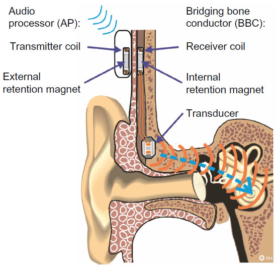 | Figure 1 Illustration of the bone conduction implant system. |
A complete risk assessment of the BCI implant in MRI would address many issues, such as local tissue heating, size of image artifacts, implant activation, and implant dislocation (force and torque). Furthermore, it should also be investigated whether the implant can withstand MRI without deteriorating in performance to the extent that a new implant is required.
Currently, the BCI is not approved for MRI, and the patients in the ongoing clinical study are informed that MRI is contraindicated since further investigations are required. The BCI will instead be temporarily removed before scanning and the surgical procedure for explantation of the BCI has been tested and found to be safe and simple.12
Technical performance
In this paper, the technical performance of the BCI has been evaluated in terms of maximum power output (MPO), total harmonic distortion (THD), and retention force. The MPO is the maximum output force level of the transducer, given in decibels relative to 1 μNewton (dB re 1 μN). This level is limited by the maximum battery power and is obtained at 90 dB sound pressure level (SPL), which is the saturation level. The THD was measured at 70 dB SPL and is a measure of the second order distortion of a certain fundamental frequency. It is given as the ratio in percentage of the fundamental power relative to the distortion power that occurs as harmonics in the power spectrum at multiples of the fundamental frequency. The retention force is the magnetic force between the two permanent magnets; one positioned in the implant under intact skin and one in the AP. Each magnet is positioned in the center of the transmitter and receiver coil, respectively, to establish an optimal signal transmission through the inductive link. It is important that this force is chosen carefully in relation to the patient’s skin thickness. If the retention force is too weak, the AP might easily fall off, and if it is too strong, it can be uncomfortable and painful to wear.
Aim of study
The aim of study is to investigate if the BCI implant withstands MRI at 1.5 Tesla. In particular, to compare MPO, THD, and retention force before and after MRI, as well as to estimate the size of image artifacts by scanning the implant externally attached on a test person.
Theory
The magnetic fields generated by the MRI scanner are typically divided into three different components: the static magnetic field, the radio frequency (RF) field, and the switched gradient field. The purpose of the static magnetic field is to align hydrogen protons in soft tissue of the human body. This will magnetize the body in the direction of the static field and as the hydrogen protons are aligned, they will move in a gyroscopic motion with a frequency called the Larmor frequency. Given the gyromagnetic ratio of 42.6 MHz/Tesla for hydrogen, the Larmor frequency for a 1.5 Tesla MRI scanner is 64 MHz.1,14
An image can then be generated by manipulation of the magnetization using RF signals with the same frequency as the Larmor frequency. This will flip the magnetization so it deviates from the aligned direction for a measurable time. The magnetization density and response time will vary for different tissues, which is used to distinguish different organs from each other. The higher the static magnetic field of the scanner is, the more hydrogen protons are aligned, and the stronger the signal will be, leading to an improved signal to noise ratio and a shorter scan time. In order to spatially excite and localize signals from different areas in the body, switched gradients are used to designate each spatial position with a unique Larmor frequency to be excited with RF signals.
Interference with MRI
The different fields (static, RF, and switched gradient) will interact with an implant in different ways. The strongest field is the static field, which is the main cause of demagnetization and induced force and torque on magnetic materials. It is strongest inside the bore where the field is uniform and the effects increase with increased field strength. A static field also exists around the scanner, but in the form of a non-uniform spatial gradient field, with the risk of attracting magnetic objects inside the bore by the so-called displacement force, also referred to as the missile effect. However, this force does not exist once the object is inside the scanner, since the spatial gradient is zero when the magnetic field is uniform. Furthermore, the displacement force is strongest where the spatial gradient is highest, and this location depends on how the static field is shielded around the scanner. The spatial gradient field is static and should not be confused with the time-varying switched gradient fields that are used for imaging.15 Both the switched gradients and the RF fields are time-varying with the potential of causing induction on magnetic and electrically conductive materials, resulting in vibrations, currents, heat and/or implant activation. Time-varying effects can also occur due to the static field if the object is moved in the field. More details of the basics and principles of MRI can be found in Bushong.1
The major safety concern for patients with implanted magnets that need to undergo 1.5 Tesla MRI is discomfort or pain from implant movement or in the worst-case dislocation. Static torque is induced when the magnetic materials of the implant are magnetized in a different direction than the static field. The greatest torque occurs when the two directions are perpendicular inside the bore, where the static field is strongest, but torque can also be induced by the static spatial gradient field around the scanner.
In a study by Kim et al,16 five out of 18 patients with CIs, MR conditional at 1.5 Tesla, who underwent MRI could not complete the scanning because of pain, caused by the implanted retention magnet. Even if the condition to use a protective head bandage to fix the implant was followed and the static field strength was 1.5 Tesla, this was not enough to prevent it from movement or dislocation. In a study by Cuda et al,17 the same problem was reported regarding the retention magnets of CIs. The implanted retention magnet is not mounted on anything else than its surrounding of silicon which can easily deform if the magnetic forces and torque are high enough. In the BCI, the implanted retention magnet is connected with a relatively stiff titanium bar to the transducer that is rigidly attached to the bone, see Figure 2. This design will prevent the magnet from moving and a head bandage around the head might not be needed, even if it is recommended for extra caution.
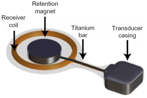 | Figure 2 Illustration of how the retention magnet in the implant is further fixed to the transducer casing by a titanium bar. |
The American Standard for Testing Materials (ASTM) has developed guidelines and recommendations on how to evaluate the MRI safety risks regarding implants. In ASTM F2052, it is specified that the maximum magnetically induced displacement force on the implant during MRI should not exceed the gravitational force due to its mass. In ASTM F2213, it is specified that the maximum magnetically induced torque should not exceed the maximum gravitational torque, calculated as the product of the gravitational force times the longest dimensional length of the implant. If these limits are exceeded, the implant design needs to be modified in order to be approved for MRI scanning.18 One such modification could be to mount the implant differently in the body or changing its magnetic properties. For example, the Sophono™ implant is fixed in the mastoid part of the temporal bone using five orthopedic screws, where each screw has a maximum holding force of >31 N resulting in total force >150 N, and thereby making it MR conditional up to 3 Tesla.19
Both the transducer and receiver coil of the BCI comprise magnetic materials. Four permanent magnets in the BCI transducer are surrounded by soft magnetic materials that are ferromagnetic. The implanted retention magnet, which is a permanent magnet, is positioned in the center of the receiver coil, see Figure 2. Some of these materials are inductive in their nature and the receiver coil comprises demodulation electronics, designed to pick up electromagnetic signals with a certain carrier frequency to drive the transducer and filter out the rest.13 It is therefore a risk for MRI induced vibrations of the transducer to be caused by induction in itself, in the receiver coil and in the transducer. In that sense, it is more relevant to investigate the vibrations of the transducer, rather than only the induced voltage in the receiver coil. Furthermore, transducer vibrations will be heard if they are intense enough within the audible frequency range of the human ear. In a study by Todt et al,20 some of the major side effects after MRI with the VSB were found to be middle ear pain from movement and transducer dislocation, and loud induced sound. However, no signs of sensorineural hearing loss caused by the loud sound were observed afterward.
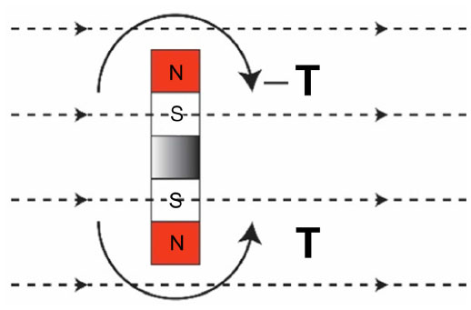
The static MRI induced torque on the BCI will mainly be caused by the implanted retention magnet, since it is the strongest and biggest magnet in the implant and its magnetization direction deviates from the direction of the static field during MRI, see Figure 3.
 | Figure 3 The internal retention magnet is subjected to a magnetically induced torque, T (solid line), during magnetic resonance imaging (MRI) if its magnetization, m, deviates from the static magnetic field of the MRI scanner (dashed lines). |
In a study by Fredén Jansson et al,21 the maximum induced torque on the implanted retention magnet of the BCI was found to be 0.20±0.01 Nm when the directions of the two fields were perpendicular. The four permanent magnets in the transducer are smaller than the retention magnet and positioned with their magnetization direction opposed in a counteracting way so that the force and torque of the transducer is reduced, see Figure 4.
 | Figure 4 Two permanent magnets with opposing poles in the same rigid body, such as in the transducer, will establish a balance that eliminates the total magnetically induced torque, T (solid lines) when it is exposed to the static magnetic field (dashed lines). |
The risks with demagnetization of the permanent magnets are deteriorated transducer performance and loss in retention force. A loss in transducer performance may only require a refitting to the patient’s hearing AP if the MPO has not decreased dramatically and a loss in retention force of up to 33% can be regained by just changing to a stronger magnet in the AP. To avoid demagnetization, the BCI implant uses a retention magnet with a coercive field strength that is higher than the static magnetic field of the MRI scanner, and the permanent magnets in the transducer are surrounded by soft magnetic materials that guide a portion of the field away from the magnets (Figure 5).
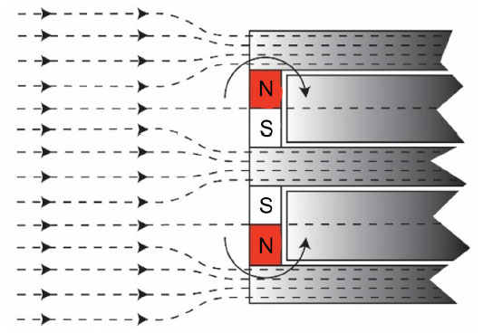 | Figure 5 The permanent magnets in the transducer are protected toward demagnetization by the surrounding soft magnetic materials that can conduct magnetic fields (dashed lines), and with the opposing magnetic poles, the torque (solid lines) is further reduced. |
In the MRI specification sheets for some other implants, there are guidelines on how to position the patient’s head to reduce force and torque, and solutions with rotatable magnets that align with the static magnetic field to avoid demagnetization, force, and torque.22,23
Image artifacts
Both magnetized objects and materials with susceptibilities different from soft tissue will create inhomogeneity in the static field and cause image artifacts. In the worst case, the image can get distorted to the extent that a correct diagnosis cannot be confirmed, as shown in the study by Kim et al,16 where a young child with bilateral CIs was scanned to assess for bacterial meningitis. This was also the case in a study by Steinmetz et al24 when a 29-year old patient with vestibular schwannoma was scanned with a Bonebridge™ implanted on the contralateral side. The image artifact distorted the whole brain image, and in particular, the cerebellopontine angle where the tumor was located. Guidelines on how to evaluate the image artifacts are given in the ASTM standard F2119. This standard states that the image artifact is not considered as a direct safety risk for the patient, since it will only aggravate the diagnosis and there are no restrictions for the maximum allowed size of the artifacts. However, the artifacts should be evaluated and documented in order to know possible scanning parts, and in cases when an image of a distorted area is required, the implant should be explanted before MRI. Other parts of the body that are not affected by the artifacts might be imaged with the implant in place, but other effects, such as loud noise from implant activation, can still occur.16,20 The manufacturers of today’s commercially available transcutaneous BCDs and many other implants have specified the size of the corresponding MRI artifact, such as a sphere of 15 cm in diameter with Bonebridge™, a distance of 5–10 cm from the Sophono™ implant and 11.5 cm from the center of Baha® Attract implant.23,22,25 These artifact sizes are specified and valid only for certain pulse sequences and might change to either better or worse with other pulse sequences or scanner models. A statistical analysis of case reported artifacts from CIs was carried out in the study by Kim et al.16 The average value of the artifacts based on eleven brain scans, was calculated both with and without the implanted retention magnet in place to 7.43±2.03 cm and 4.16±1.19 cm, respectively.
The upper trunk (shoulder and head) is the most critical region when it comes to scanning of patients with hearing implants, since the image artifact will cover the area close to the implant. The reasons for scanning patients with implants in MRI are the same as for patients without an implant, but when CT is not an alternative. However, some hearing impairments are linked to intracranial diseases, such as unilateral hearing loss and vestibular schwannoma, which requires regular MRI examinations for planning of surgery or radiation therapy and to follow the tumor growth over time.24 The MRI safety for those patients is therefore important to consider if their hearing impairment is rehabilitated with hearing implants. Some other reported reasons, not related to hearing impairment, why patients with hearing implants have had their upper trunk scanned with MRI are exclusion of a brain tumor, traffic accidents, shoulder pain, congenital atresia of the ear, bacterial meningitis, diabetes insipidus in Langerhans cell histiocytosis, optic neuritis, and preoperative planning for implantation of an auditory brainstem implant.16,20,24
Methods
One advantage of mounting the implant externally on the head is that the transducer can be pressed against the skin similar to a conventional BCD, see Figure 6. This means that vibrations from the transducer will be induced into the skull if it is driven by the AP or if sound is induced by the magnetic fields during MRI once the AP is detached. It is assumed that the external position will not influence how the implant is affected by the magnetic fields and that any MRI induced sound can be heard by the test person. Before entering the MRI environment for scanning, an AP was first attached to verify that the transducer was successfully transmitting vibrations to the skull. The AP was programmed to generate a sequence of frequencies that could be heard if the implant was functioning and firmly attached. In particular, it was used to ensure the transducer attachment in order for any MRI induced sound to be audible and was then removed before scanning.
 | Figure 6 The bone conduction implant is positioned externally on the skin behind the ear similar to conventional bone conduction devices that are driven through the skin. |
With the objective to investigate if the implant withstood 1.5 Tesla MRI, it was first tested for the static field separately, before applying any pulse sequences. During the tests, the implant was attached to a stiff plastic board to counteract any magnetically induced torque. The first test was therefore to keep only the plastic board with implant in the isocenter, but without applying any time-varying fields and verify its function with an AP after 5 minutes. After testing in the static field, the plastic board with implant was mounted to the test person’s head with a compression bandage and the AP was used to ensure good transmission of bone conducted sound via the skin. With the transducer attached properly, it was theoretically possible to hear high induced BC sound during scanning, and ear plugs were used to reduce the sound from the switched gradients. Finally, the test person’s head was scanned and the effect on MPO, THD, and retention force was objectively measured afterward. The study was done following the principles stated in the Declaration of Helsinki and written informed consent was signed. Taking part in the study was voluntary and no remuneration was given to the test person.
Implant activation during MRI
The AP is always removed before MRI and if the implant generates sound during MRI, it means that the implant has been activated by the magnetic fields from the scanner. This effect should be investigated to not worsen the patient’s already impaired hearing from too high sounds induced during MRI. In this test, and as normal procedure during scanning, the test person’s ear canals were blocked with earplugs for protection from the sound of the switching gradients. As the earplugs reduce the airborne sound, any BC sound induced from implant activation during scanning would be more easily heard. In order for this effect to be more harmful than MRI without the implant, the induced BC sound must be higher than the AC sound from the switching gradients when using earplugs. The rationale for performing subjective tests was that the BC sound at least would have been heard in order to be harmful. Objective measurements are more complicated and mainly of interest after it has been confirmed that sound is subjectively observed.
In a study by Teissl et al,26 it was found that voltage in the receiver coil is most likely to be induced if the frequency of the RF field is close to the carrier frequency of the induction link. The amount of induced voltage will also depend on the incident angle of the time-varying magnetic field. In theory and according to Faraday’s law, maximum voltage is induced when the incident angle and the receiver coil’s flat surface are perpendicular to each other and no voltage is induced when they are parallel.14 The implant can be positioned on either the patient’s right or left ear, and the effect on the magnetic induction will be the same for both sides except that the reflection causes a 180 degrees phase difference.
Imaging
To scan the implant, a General Electric Healthcare 1.5 Tesla HDe MRI scanner (GE Healthcare, Buckinghamshire, UK) with an 8-channel head coil was used. The pulse sequences were routine sequences for brain and cerebellum imaging recommended by the scanner manufacturer. The ASTM standard F2119 suggests that images from both gradient-echo (GE) and spin-echo (SE) pulse sequences in three orthogonal planes (sagittal, coronal, and axial) are obtained when evaluating image artifacts. These guidelines were followed and reference images were taken without the implant in place for comparison reasons.
Implant performance after MRI
The performance of the implant before and after MRI was measured on a skull simulator TU1000 (Nobelpharma, Göteborg, Sweden) in an anechoic chamber B&K 4222 (Brüel and Kjaer, Nærum, Denmark). The measurement was controlled and executed in Soundcheck (Varst Technology A/S, Højberg, Denmark) software via a universal serial bus (USB) fireface soundcard, and the speaker was driven by an amplifier, ROTEL RB-976 MkII (The Rotel Co, Ltd, Tokyo, Japan), see Figure 7 for the measurement setup.
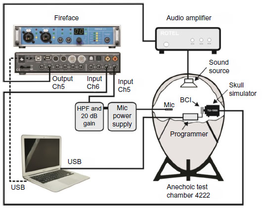 | Figure 7 The equipment used to measure maximum power output and total harmonic distortion. |
Directly after scanning, the performance was measured objectively in terms of MPO, THD, and retention force. The demagnetization was measured as loss in retention force in percent after MRI. The retention force was measured at a distance of 2 mm between the AP and implant using a force gauge model FG-5000A from Lutron Electronic Enterprise Co, Ltd, Taipei, Taiwan, with the measurable range from 1 g to 5 kg and resolution of ±1 g.
Results
The electro-acoustic performance
The MPO was obtained at 90 dB SPL between 100 and 10,000 Hz and is shown in Figure 8, before and after MRI. For all frequencies, the average loss in MPO after MRI was found to be 1.1 dB with a standard deviation of 2.1 dB.
 | Figure 8 The maximum power output from the implant before (dashed line) and after MRI (solid line) acoustically measured at 90 dB SPL. |
The THD of the implant obtained at 70 dB SPL between 100 and 10,000 Hz is shown in Figure 9 before and after MRI. The THD remained low and essentially unchanged between 300 and 8,000 Hz, but increased with 24.9% at 125 Hz. For all frequencies, the average increase in THD after MRI was found to be 1.5%±5.0%.
 | Figure 9 The total harmonic distortion of the implant before (dashed line) and after MRI (solid line), measured at 70 dB SPL. |
The retention force was measured at a distance of 2 mm (the thickness of the plastic board) between the AP and implant to 1.76 N before MRI and 1.67 N after MRI, corresponding to a demagnetization of ~5%.
Image artifacts
The maximum image artifacts for the SE and GE sequences in three orthogonal planes (sagittal, coronal, and axial) are shown in Figure 10 together with the corresponding reference image without implant. The maximum size of each artifact was measured as the maximum distance from the implant in the sagittal, coronal, and axial plane to 9, 10, and 9 cm for the GE pulse sequence and 8, 9, and 8 cm for the SE pulse sequence, respectively.
 | Figure 10 The MRI images in three orthogonal planes (sagittal, coronal, and axial) in a 1.5 Tesla scanner without implant (first and third column) and with implant (second and fourth column) for one spin-echo and one gradient-echo sequence, respectively. |
Discussion
The results indicate that the present BCI design can withstand 1.5 Tesla MRI. However, this is a pilot study and there is no statistical evidence, which suggests that further investigations are required if MRI examinations need to be performed on BCI patients. Today, the implant will be explanted before a necessary MRI if no alternative imaging modality can be used, as the method for implant removal has been tested and verified as simple and safe.12 One of the BCI exclusion criteria is if the patient will need to undergo MRI scanning in the future.
The specially programmed AP is a tool that was used to verify that the attachment of the externally worn implant had been done properly for induced sound to be heard. It was also used to ensure that the implant was not completely damaged after exposure to only the static field of the MRI scanner. The investigation of induced sound was only done subjectively and objective measurements should be performed for a more thorough investigation.
Patients are typically wearing protective earplugs during MRI because of the high sound caused by switching the gradients. In order for MRI induced BC sound to be more harmful for hearing than MRI itself, it must be higher than the airborne sound from the switched gradients heard when using earplugs. No sound was observed by the test person; however, these results are only valid for this specific test person and MRI scanner. Other MRI scanners from different manufacturers and other field strengths with the Larmor frequency closer to the carrier frequency,26 as well as other pulse sequences, might give different results. As an example, in the study by Todt et al,20 five out of 12 patients with the VSB who were scanned in 1.5 Tesla MRI complained of a loud bang or continuous noise, whereas the rest did not.
A minor deterioration in transducer performance was detected in the MPO and THD measurements that can be due to demagnetization of the internal magnets and change in soft magnetic material properties or air gap size due to mechanical stress. In a study by Fredén Jansson et al,21 the average demagnetization of the implanted retention magnet of the BCI after exposure to a uniform magnetic field of 1.5 Tesla was found to be 7.7%±2.5%, and the 5% loss in this study is within that range. This is considered to be a small and acceptable loss, since a force of up to 33% can be regained by changing to a stronger magnet in the AP.
The image artifacts caused by the BCI are similar to other BCDs and are worst close to the implant, covering an area of approximately half of the head. Imaging of the tissues surrounding the implanted ear (ipsilateral) is therefore not possible without removing the implant, but imaging of the other ear (contralateral) can still be conducted. Patients who are diagnosed with vestibular schwannoma (benign tumor on the vestibular nerve) are likely to get unilateral hearing loss, or SSD, from the disease itself, radiation therapy or surgery. When BCDs are used for rehabilitation of unilateral hearing loss or SSD patients, vibrations are transmitted from the ipsilateral, impaired cochlea through the skull bone to the functioning contralateral cochlea. Unfortunately, the standard way of analyzing the tumor growth for those patients is primarily done with MRI analysis. In a study by Güldner et al,27 the idea of combining CT with contrast agents to visualize soft tissue was presented as an alternative to MRI when the inner ear structures are distorted in the image. However, this was later claimed by Steinmetz et al not to work in practice.24 The alternative would be to use a percutaneous BCD, such as BAHA, which gives smaller artifacts than today’s available transcutaneous BCD choices.24,28
In general, image artifacts seem to be the only critical aspect with scanning the BCI in 1.5 Tesla MRI, since they cover almost half of the brain image, while the loss in performance and retention force are within acceptable limits. Some further millimeters might be added for the recess in the bone and the skin thickness that are missing when the implant is placed externally on the head. However, if patients regularly need to have MRI examinations, it should be investigated whether the implant withstands repetitive exposure to the magnetic fields in the MRI scanner.
Conclusion
The BCI implant was placed externally on the skin of a test person’s head to simulate the real case scenario when the implant is positioned under the skin. With the BCI implant in place, the test person was scanned in a 1.5 Tesla MRI scanner. No induced sound or implant movement was observed by the test person. The BCI implant withstood the scanning of two sequences with minor effects on performance as follows:
- The MPO decreased with an average of 1.1±2.1 dB between 100 and 10,000 Hz.
- The THD increased mainly at low frequencies below 300 Hz with the maximum of 24.9% at 125 Hz.
- The retention force decreased with 5%.
- An image artifact will not harm the patient directly, but aggravate the diagnosis with a distorted image within a maximum distance of 10 cm from the implant.
In future studies, measurements on more subjects will be conducted, as well as objective measurements on induced sound and heat.
Acknowledgment
This study was supported by VR, the Swedish Research Council.
Disclosure
Bo Håkansson is the inventor of some BCI patents. The authors report no other conflict of interest in this work.
References
Bushong SC. Magnetic Resonance Imaging: Physical and Biological Principles, 3rd Edition. Texas, USA: Mosby; 2003. | |
Cochlear™. MRI for Nucleus® Cochlear Implant Recipients. Radiographer’s instructions for Australia and New Zealand. Cochlear™. Available from: http://www.cochlear.com/wps/wcm/connect/f6316d39-fbb2-412d-b835-45b637512e16/GD4319-CL-Radiographers-Guide-Oct-2013.pdf?MOD=AJPERES&CONVERT_TO=url&CACHEID=f6316d39-fbb2-412d-b835-45b637512e16. Accessed August 31, 2015. | |
Håkansson B, Tjellström A, Rosenhall U. Hearing thresholds with direct bone conduction versus conventional bone conduction. Scand Audiol. 1984;13(1):3–13. | |
Oticon Medical. Oticon Medical. Industry Symposia: Oticon Medical at the Osseo 2015, 5th international congress on bone conduction hearing and related technologies, Lake Louise, Canada. | |
Dun CA, Faber HT, de Wolf MJ, Mylanus EA, Cremers CW, Hol MK. Assessment of more than 1,000 implanted percutaneous bone conduction devices: skin reactions and implant survival. Otol Neurotol. 2012; 33(2):192–198. | |
Kiringoda R, Lustig LR. A Meta-analysis of the complications associated with osseointegrated hearing aids. Otol Neurotol. 2013; 34(5):790–794. | |
Snik AF, Mylanus EA, Proops DW, et al. Consensus statements on the BAHA system: where do we stand at present? Ann Otol Rhinol Laryngol Suppl. 2005;195:2–12. | |
Reinfeldt S, Håkansson B, Taghavi H, Eeg-Olofsson M. New developments in bone-conduction hearing implants: a review. Med Devices (Auckl). 2015;16(8):79–93. | |
Jesacher MO, Kiefer J, Zierhofer C, Fauser C. Torque measurements of the ossicular chain: implication on the MRI safety of the hearing implant Vibrant Soundbridge. Otol Neurotol. 2010;31(4):676–680. | |
Beltrame AM, Martini A, Prosser S, Giarbini N, Streitberger C. Coupling the Vibrant Soundbridge to cochlea round window: auditory results in patients with mixed hearing loss. Otol Neurol. 2009;30(2):194–201. | |
MED-EL. VIBRANT SOUNDBRIDGE® SYSTEM. Including the SAMBATM Audio Processor, the VORP 503 and the Vibroplasty Couplers. MED-EL. Available from: http://s3.medel.com.s3.amazonaws.com/pdf/28477_10_Factsheet%20VSB%20System%20%28english%29-8seitig_screen6.pdf. Accessed August 31, 2015. | |
Reinfeldt S, Håkansson B, Taghavi H, Fredén Jansson KJ, Eeg-Olofsson M. The bone conduction implant – clinical results of the first six patients. Int J Audiol. 2015;54(6):408–416. | |
Taghavi H, Håkanson B, Reinfeldt S, et al. Technical design of a new bone conduction implant (BCI) system. Int J Audiol. 2015:1–9. | |
Nordling C, Österman J. Physics Handbook for Science and Engineering. 8th ed. Lund, Sweden: Studentlitteratur; 1996. | |
Shellock FG, Kanal E, Gilk T. Regarding the value reported for the term “spatial gradient magnetic field” and how this information is applied to labeling of medical implants and devices. AJR Am J Roentgenol. 2011; 196(1):142–145. | |
Kim BG, Kim JW, Park JJ, Kim SH, Kim HN, Choi JY. Adverse Events and Discomfort During Magnetic Resonance Imaging in Cochlear Implant Recipients. JAMA Otolaryngol Head Neck Surg. 2015; 141(1):45–52. | |
Cuda D, Murri A, Succo G. Focused tight dressing does not prevent cochlear implant magnet migration under 1.5 Tesla MRI. Acta Otorhinolaryngol Ital. 2013;33(2):133–136. | |
Shaefers G. Testing MR safety and compatibility: an overview of the methods and current standards. IEEE Eng Med Biol Mag. 2008; 27(3):23–27. | |
US Food and Drug Administration [homepage on the Internet]. 510(k) Premarket Notification number K123962. FDA; [updated August 24, 2015]. Available from: http://www.accessdata.fda.gov/scripts/cdrh/cfdocs/cfpmn/pmn.cfm?ID=42166. Accessed August 31, 2015. | |
Todt I, Wagner J, Goetze R, Scholz S, Seidl R, Ernst A. MRI scanning in patients implanted with a Vibrant Soundbridge. Laryngoscope. 2011; 121(7):1532–1535. | |
Fredén Jansson KJ, Håkansson B, Taghavi H, Reinfeldt S, Eeg-Olofsson M. MRI induced torque and demagnetization in retention magnets for bone conduction implants. IEEE Trans Biomed Eng. 2014;61(6):1887–1893. | |
Sophono®. Sophono® Bone Implant Precautions, MRI Technologist’s Guide. Sophono®. Available from: http://sophono.com/wp-content/uploads/S0595-rA-MRI-specification-sheet.pdf. Accessed August 31, 2015. | |
MED-EL. The BONEBRIDGE™ Bone Conduction Implant System, For Professionals. MED-EL. Available from: http://www.medel.com/data/downloadmanager/downloads/BONEBRIDGE_pro/en-GB/BB_Brochure_EN_screen.pdf. Accessed August 31, 2015. | |
Steinmetz C, Mader I, Arndt S, Aschendorff A, Laszig R, Hassepass F. MRI artifacts after Bonebridge implantation. Eur Arch Otorhinolaryngol. 2014;271(7):2079–2082. | |
Cochlear™. Cochlear™ Baha® Attract System®, Radiographer’s instructions for MRI. Cochlear™. Available from: http://www.content.usz.ch/non_cms/orl/ci-zentrum/tipps/MRI_Radiographers_Instructions_Baha_4_Attract_Sys.pdf. Accessed August 31, 2015. | |
Teissl C, Kremser C, Hochmair ES, Hochmair-Desoyer IJ. Cochlear implants: in vitro investigation of electromagnetic interference at MR imaging – compatibility and safety aspects. Radiology. 1998; 208(3):700–708. | |
Güldner C, Heinrichs J, Weiss R, et al. Visualisation of the Bone bridge by means of CT and CBCT. Eur J Med Res. 2013;18:30. | |
Fritsch MH, Naumann IC, Mosier KM. BAHA devices and magnetic resonsnce imaging scanners. Otol Neurotol. 2008;29(8):1095–1099. |
 © 2015 The Author(s). This work is published and licensed by Dove Medical Press Limited. The
full terms of this license are available at https://www.dovepress.com/terms
and incorporate the Creative Commons Attribution
- Non Commercial (unported, 3.0) License.
By accessing the work you hereby accept the Terms. Non-commercial uses of the work are permitted
without any further permission from Dove Medical Press Limited, provided the work is properly
attributed. For permission for commercial use of this work, please see paragraphs 4.2 and 5 of our Terms.
© 2015 The Author(s). This work is published and licensed by Dove Medical Press Limited. The
full terms of this license are available at https://www.dovepress.com/terms
and incorporate the Creative Commons Attribution
- Non Commercial (unported, 3.0) License.
By accessing the work you hereby accept the Terms. Non-commercial uses of the work are permitted
without any further permission from Dove Medical Press Limited, provided the work is properly
attributed. For permission for commercial use of this work, please see paragraphs 4.2 and 5 of our Terms.