Back to Journals » International Journal of Nanomedicine » Volume 12
Fast-degrading PLA/ORMOGLASS fibrous composite scaffold leads to a calcium-rich angiogenic environment
Authors Sachot N, Roguska A, Planell JA, Lewandowska M, Engel E, Castaño O ![]()
Received 28 February 2017
Accepted for publication 10 May 2017
Published 11 July 2017 Volume 2017:12 Pages 4901—4919
DOI https://doi.org/10.2147/IJN.S135806
Checked for plagiarism Yes
Review by Single anonymous peer review
Peer reviewer comments 2
Editor who approved publication: Dr Thomas Webster
Nadège Sachot,1,2 Agata Roguska,3 Josep Anton Planell,1,2 Malgorzata Lewandowska,3 Elisabeth Engel,1,2,4 Oscar Castaño1,2,5,6
1Biomaterials for Regenerative Therapies, Institute for Bioengineering of Catalonia (IBEC), Barcelona, 2CIBER en Bioingeniería, Biomateriales y Nanomedicina, CIBER-BBN, Zaragoza, Spain; 3Faculty of Materials Science and Engineering, Warsaw University of Technology, Warsaw, Poland; 4Department of Materials Science and Metallurgical Engineering, Universitat Politècnica de Catalunya (UPC), 5Department of Materials Science and Physical Chemistry, Universitat de Barcelona (UB), 6Department of Engineerings: Electronics, Universitat de Barcelona, Barcelona, Spain
Abstract: The success of scaffold implantation in acellular tissue engineering approaches relies on the ability of the material to interact properly with the biological environment. This behavior mainly depends on the design of the graft surface and, more precisely, on its capacity to biodegrade in a well-defined manner (nature of ions released, surface-to-volume ratio, dissolution profile of this release, rate of material resorption, and preservation of mechanical properties). The assessment of the biological behavior of temporary templates is therefore very important in tissue engineering, especially for composites, which usually exhibit complicated degradation behavior. Here, blended polylactic acid (PLA) calcium phosphate ORMOGLASS (organically modified glass) nanofibrous mats have been incubated up to 4 weeks in physiological simulated conditions, and their morphological, topographical, and chemical changes have been investigated. The results showed that a significant loss of inorganic phase occurred at the beginning of the immersion and the ORMOGLASS maintained a stable composition afterward throughout the degradation period. As a whole, the nanostructured scaffolds underwent fast and heterogeneous degradation. This study reveals that an angiogenic calcium-rich environment can be achieved through fast-degrading ORMOGLASS/PLA blended fibers, which seems to be an excellent alternative for guided bone regeneration.
Keywords: electrospinning, fast degradation, ORMOGLASSES, angiogenesis, nanofibers, calcium release
Introduction
Materials for tissue engineering should fulfill numerous precise criteria in order to be considered as ideal implants. Mainly, they should be biocompatible, bioactive, and act as a 3D template for cellular activity in order to be well integrated with the surrounding biological environment of the implant site and to trigger specific cellular responses.1 As part of the so-called “third generation” of biomaterials, smart acellular scaffolds should additionally degrade at a suitable rate to enable these processes to take place throughout the progressive resorption of the material.2 The final goal is the design of implanted constructs that induce newly formed functional tissue that will remain at the end of the regeneration process, and which require no additional surgical procedures for removal. The biodegradability of a substrate is therefore very important and can even be critical with regard to the effectiveness of the graft in promoting the body’s inherent capacity to heal and self-repair and act as a cell-homing promoter. If toxic by-products are released during degradation of a biomaterial, for example, the local healthy tissue is not preserved, and tissue regeneration will not properly occur. Scar tissues can consequently be formed, attesting to unsuitable interactions between the template and the host tissue.3
Many parameters such as architecture, porosity, hydrophilicity, crystallinity, and chemical composition can affect the biodegradation mechanisms of a biomaterial.4,5 This depends on its design and, more precisely, on its constituents and method of fabrication (structure features: shape, size, interconnected porosity, etc). Depending on the clinical use and the tissue targeted (soft or hard), different material properties are needed. For bone engineering, hybrid biomaterials made of synthetic or biodegradable polymer and bioactive glasses are interesting composites, as they are able to form a stable implant–host tissue interface and even trigger the desired cellular responses (ie, osteogenesis and angiogenesis).4,6,7 The incorporation of an inorganic phase into an organic one generally allows a better control of the degradation of the polymeric matrix, thanks to an increase in hydrophilicity, which implies a better wetting contact between the polymer and the physiological fluid as well as micro- and nanoporosity, increasing the surface area and enhancing hydrolytic degradation.8 This is an interesting point regarding the use of some polymers such as polyglycolic or polylactic acid (PLA), which tend to degrade faster in vivo9,10 in comparison to other aliphatic polymers such as polycaprolactone (PCL), which remains for a longer time in the body after implantation.11,12 By dissolving in the surrounding fluid, bioactive glasses also resorb in vivo.6,13,14 Thus, by combining these two families of materials, fully bioresorbable scaffolds with remarkable mechanical and bioactive properties can be produced. However, biodegradation is a complex mechanism influenced by several biological connected factors, as for example fluid pH and infiltration, oxygen supply, and enzyme activity,15,16 so an exact control of the process is difficult to achieve, especially if it aims to satisfy precise expectations, such as a specific degradation rate or a time-scaled product release. Despite these drawbacks, however, it is essential to assess the degradation behavior of a scaffold, as it will closely affect the future of the template after implantation (changes in mechanical properties and induced cellular response) and consequently determine its success.
One of the most popular methods to increase surface-to-volume ratio at the nanoscale is electrospinning, which is also the most cost-effective way to mimic the extracellular matrix (ECM).17 Its versatility and simplicity allows the fibers to be modified to almost any configuration or biomolecule-loading ability, depending on the application.18,19
The aim of this study was to investigate the morphological, topographical, and chemical modifications that a PLA–titanium-based bioactive glass (OG5) scaffold undergoes during in vitro degradation when physiological conditions are simulated. PLA–OG5 fibers developed for bone engineering have been produced using the electrospinning technique and then immersed in simulated body fluid (SBF) for different periods of time.
Materials and methods
Materials
To produce the titanium-based organically modified glass (ORMOGLASS), calcium and sodium 2-methoxyethoxide, phosphorus ethoxide, and titanium tetraisopropoxide precursor solutions were mixed to obtain a glass precursor mix with the OG5 glass composition (44.5P2: 44.5Ca: 6Na: 5Ti molar ratio). These solutions were prepared in our laboratory as reported previously.14 Basically, Ca (Panreac, Barcelona, Spain; 98%) and Na (Panreac; 99.8%) precursors were prepared by refluxing metallic Ca and Na in dry 2-methoxyethanol (Sigma-Aldrich, St. Louis, MO, USA; 99%). P precursor solution was obtained by refluxing P2O5 (Sigma-Aldrich; 99.99%) in absolute ethanol (Panreac; 99.5%). Ti alkoxide precursor was obtained by diluting commercial Ti tetraisopropoxide (Alfa Aesar, Haverhill, MO, USA; 97%) in absolute ethanol as well. Precursors were mixed and stirred to obtain the targeted composition. A catalyst of Ti:H2O:NH3:isopropanol with molar ratio of 1:60:4.5:100 was additionally added into the precursor solution mix to initiate hydrolysis.
Fiber preparation
Fibers were produced by electrospinning. A blend made of a solution of 4% w/w of PLA (70/30 L-lactide/DL-lactide copolymer, Corbion PLDL 7038) in 2,2,2-trifluoroethanol (TFE, Panreac; 99.8%) and the previous partially hydrolyzed ORMOGLASS was prepared according to two glass:polymer volume ratios: 10–90 and 20–80 (v:v). Fibers (OG5 10–90 and OG5 20–80) used in this study were collected on a flat aluminum support and were therefore obtained as nonwoven mats. The setup parameters for the fiber deposition were: 18 cm distance tip-collector, 8 kV voltage, and 0.5 mL/h dispensing rate. More details on the preparation and fabrication methods of these hybrid fibers can be found in a previously published study.14
Incubation conditions
The in vitro assay was performed with OG5 10–90 and OG5 20–80 random fibers. The 5×30×0.5 mm fiber strips were cut from the electrospun fibrous layer, rinsed for 1 hour in water, and immersed in c-SBF at 37°C up to 28 days. Each fiber strip was introduced into an individual flask containing 30 mL c-SBF.20 The SBF preparation and determination of SBF quantity necessary for the study were selected according to the conditions reported by Kokubo and Takadama.21 SBF was changed every 2 days. Fibers were removed from the SBF at different time points (1 hour, 1 day, 3 days, 7 days, 21 days, 28 days), rinsed three times with ultra-pure water, and dried under vacuum for at least 3 days before characterization.
Fiber morphological characterization
Pieces were cut from the dried incubated fibrous layer and fixed on the metallic support used for scanning electron microscopy (SEM) to assess the fiber morphology (Hitachi S-5500). Samples were coated with a thin layer of carbon in order to enhance the quality of the pictures. Pictures were taken at a 5 kV voltage and a height distance of 5 mm. Field-emission scanning electron microscopy (FESEM, Nova™-Nano SEM-230; FEI Co., Hillsboro, OR, USA) was also used to obtain a better resolution.
Fiber topography
To assess the topographical changes occurring at the fiber surface, atomic force microscopy (AFM) was used. Measurements were operated using an AFM MultiMode8, Bruker machine, and the PeakForce QNM method in air under ambient conditions. Image processing and data analysis were performed with the Nanoscope Analysis software v1.2.
Chemical changes
Chemical composition of the fibers was assessed by energy-dispersive X-ray spectroscopy (EDS, Quanta 200 XTE; FEI Co.). This technique enables the determination of the fiber composition by determining the relative molar ratio of the different elements with regards to the other compounds (percentage). Samples already used for FESEM observations were also used to perform the element quantification. Measurements were performed at different time points at three arbitrarily selected locations on the samples.
Fourier-transform infrared spectroscopy in attenuated total reflectance mode (FTIR-ATR, Nicolet 8700; Thermo Scientific, Waltham, MA, USA) was also used to evaluate the chemical changes. No preliminary treatments were applied to the samples before performing these measurements.
Calcium dissolution and pH measurements
Given the importance that calcium ions play regarding cellular activity, dissolution tests were carried out to monitor the release profile of the calcium contained in the hybrid fibers during their degradation. Pieces of 1 cm2 were cut from the electrospun fibrous layer. Four replicates were prepared for each fiber type (OG5 10–90 and OG5 20–80, random) and at each time point. Each sample was placed in a well of a 24-well culture plate. Deionized water was added to each well (1 mL) and parafilm was used to properly seal the plate in order to avoid water evaporation. Following this, the plate was placed in an incubator at 37°C. After each time point (5 min, 1 hour, 1 day, 2 days, 3 days, 6 days, 7 days, 8 days, 9 days, 10 days, 13 days, and 14 days), the water was removed and 1 mL was again added to the wells. Calcium concentrations were measured using a Crison Ca2+ selective electrode and an Ag/AgCl reference electrode. pH was additionally measured using a Crison GLP22+ pH-meter and a Crison pH microelectrode. Initially, this assay was performed in SBF. However, it has been noticed that the buffering effect of SBF partially masked the real observation of the dissolution behavior of the material. Therefore, instead of SBF, deionized water was preferred to perform this assay in order to determine the real amount of calcium released by the material. The results with SBF are reported in Figure S1. The calcium concentration is reported as a cumulative value.
Polymer thermal properties
Differential scanning calorimetry (DSC) analysis was performed to check if changes in the organic phase occurred during the degradation assay. A DSC Q2000 TA device and 1.20 mg samples confined in hermetic aluminum pans were used. Samples (fibers not incubated and incubated at 1 hour, 3 days, 7 days, 21 days) were heated at a rate of 10°C/min starting from −20°C up to 180°C. The same heating ramp was again applied to the samples after cooling. Nitrogen was used as a purging gas.
Melting and crystallization properties were evaluated by analyzing the curve of the first heating ramp of the DSC assays. The small bump associated with the melting peak of the hybrid fibers is particularly taken into account because it had been noticed that it changed during the degradation test. Even though not observed on the DSC curves previously shown, the crystallization peak is also taken into account here in order to verify if the degradation test influenced the crystallization behavior of the polymer over time.
The crystallinity of composite materials is given by the following equation:22,23
|
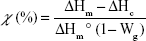
where χ is the percentage of crystallinity, ΔHm is the heat of fusion, ΔHc is the heat of the cold crystallization, ΔHm° is the heat of fusion of a 100% PLA crystalline material (93.1 J·g−1),24 and Wg the weight percent of glass contained in the hybrids. For this assay, the exact Wg is not known because the materials degraded over time. It is thus not possible to calculate precisely the crystallinity of each sample. However, even if an accurate value of crystallinity cannot be obtained, the heat of fusion and cold crystallization (if observed) can be determined and be used to discuss changes in the theoretical crystallinity of the fibers; even without knowing precisely the Wg values. This is possible thanks to mathematical considerations made in the equation above.
The glass transition temperature (Tg) was determined considering the second heating cycle and using the inflexion point method. The TA Universal Analysis software v4.7A was used to analyze all DSC curves.
Determination of glass loss
Incubated fibers were subjected to thermal degradation in order to compare the quantity of inorganic phase contained in the fibers before and after incubation. Small quantities of samples were placed in aluminum pans and heated from room temperature up to 700°C at a heating rate of 10°C/min in air. Thermograms were analyzed with the TA Universal Analysis software v4.7A. The weight percent remaining at the end of the thermal treatment corresponds to the amount of inorganic compound present in the studied material. However, if the inorganic material is not completely inorganic but contains some organic fragments (as in the ORMOGLASS), the remaining weight does not exactly correspond to the amount of glass contained in the fibers. If detected by thermogravimetric analysis (TGA), the weight loss due to the organic fragments of the ORMOGLASS should be also considered to quantify the glass content. Finally, the content of the glass is approximated by adding the remaining weight loss of the inorganic phase and the weight loss associated to the organic fragments of the ORMOGLASS.
Glass distribution in the fibers
Transmission electron microscopy (TEM) observations were also performed to assess the dispersion of the glass in the polymeric matrix before and after incubation. A few fibers were extracted from the layers and deposited on a carbon-coated copper grid for analysis. A JEOL JEM 1200 EX (JEOL, Tokyo, Japan) instrument was used and the accelerating voltage was set at 120 kV.
Statistical analysis method
Results of multiple measurements have been presented as the average ± standard deviation.
Results
Fiber morphology
Figure 1 shows the morphology of the fibers as produced by electrospinning and the evolution of their aspect over the duration of the assay (1 days, 7 days, and 21 days of immersion in SBF). For PLA, no significant differences were observed except a small increase in roughness that appeared with time (wrinkles). For the hybrid fibers, more drastic differences occurred rapidly. Fibers collapsed and subsequently opened following the fiber length in two different ways. The first one looked like an instantaneous crack that revealed a cavity (Figure 1 red arrow). The other seemed to be rather due to a slow process that induced the opening of the fibers (Figure 1 blue arrow). After 21 days, hybrid fibers additionally showed a nonsmooth surface which seemed more obvious than for the PLA ones. This is especially well observed for the fibers that possessed the higher ORMOGLASS ratio (Figure 1 green arrow).
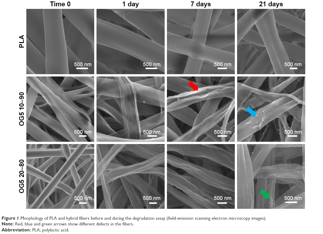 | Figure 1 Morphology of PLA and hybrid fibers before and during the degradation assay (field-emission scanning electron microscopy images). |
Typical fiber morphological changes are presented with better resolution in Figure 2 (representative images of the diverse observed “defects”). The appearance of wrinkles on PLA is relevant, as well as the surface modifications that occurred for the hybrid fibers. Images attested that fibers collapsed and underwent considerable surface changes. Finally, these pictures showed that PLA fibers maintained their cylindrical morphology during the immersion period while hybrid fibers lost their round fiber shape and degraded faster.
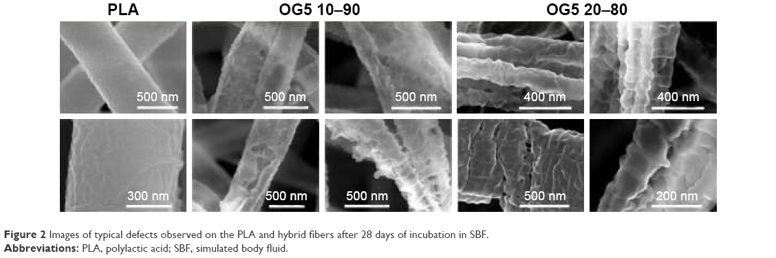 | Figure 2 Images of typical defects observed on the PLA and hybrid fibers after 28 days of incubation in SBF. |
Fiber topography
During the degradation period, hybrid fiber topography considerably changed (Figure 2). Additional pictures can be found in Figure S2. After 1 hour immersion in SBF, hybrid fibers exhibited a uniform topography with a difference in height of around 30 nm. At 1 day however, the collapsing of the fibers was already clearly seen and more consequent changes in height profile were observed (120 nm height deflection). This suggested that the surface of the fibers was rather smooth at the beginning of the assay in comparison with the later time points. At 7 days, the cracks observed on FESEM pictures were also detected by the AFM. Finally, at 21 days, the surface of the fibers had significantly changed, as noticed with the profile undulations between 0 and 500 nm width. The change in height between 500 nm and 700 nm width was attributed to the part of the fibers that collapsed (see Figure 3).
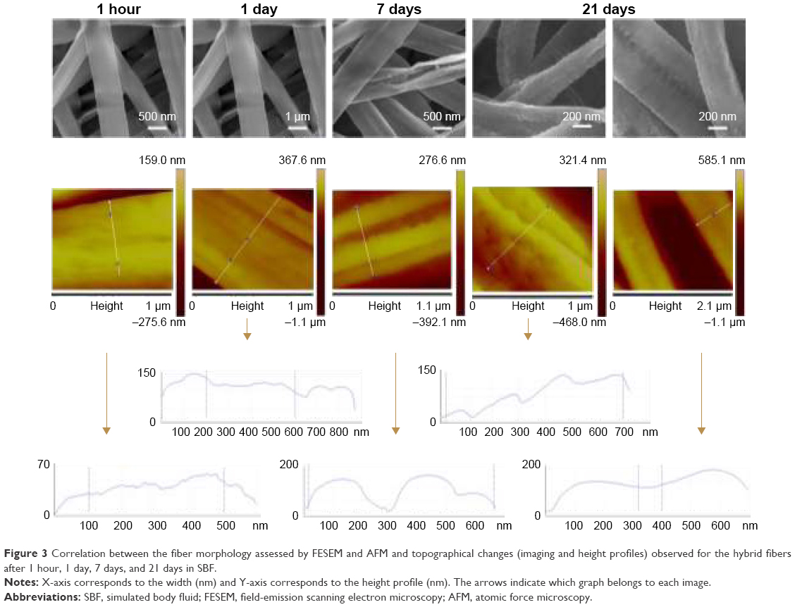 | Figure 3 Correlation between the fiber morphology assessed by FESEM and AFM and topographical changes (imaging and height profiles) observed for the hybrid fibers after 1 hour, 1 day, 7 days, and 21 days in SBF. |
The last behavior identified by AFM is the slow opening of the fibers. On the height profile, it can be seen how the slow cracking of the fibers tends to lower the height value between the two fiber walls.
In general, AFM images are in accordance with the degradation behaviors identified with the FESEM pictures, and the evaluation of the topographical changes through the height profile determination confirmed these modifications.
Chemical changes
Fibers were successfully produced with the targeted composition (OG5). Fibers contained thus, initially, a high amount of phosphate and calcium and a low amount of sodium and titanium (Figure 4). EDS measurements on the fibers showed that after 1 hour in SBF, huge changes in ORMOGLASS composition had already occurred. The quantity of calcium dropped dramatically. The phosphate amount also decreased but in a more moderated manner. However, phosphate continued to decrease up to the first day, while the calcium percentage increased slightly. As a consequence of these changes, the titanium content increased. For the sodium, it is believed that it was already released at the early stage of incubation. For this reason, no significant changes were observed for the sodium (almost undetected by the device). After 3 days, the molar composition of the fibers remained stable up to the end of the assay, but the initial OG5 composition was not maintained. The same modifications were observed for the OG5 10–90 and OG5 20–80 fibers.
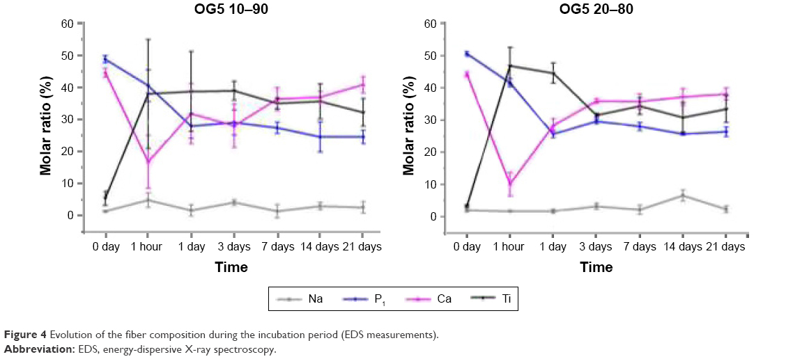 | Figure 4 Evolution of the fiber composition during the incubation period (EDS measurements). |
Figure 5 displays the infrared spectra collected on the fibers before and after degradation. The infrared spectra of the fibers obtained as produced by electrospinning exhibited the typical peaks of PLA and additional signals due to the presence of phosphate complexes: P=O stretching at 1,223 cm−1,25–28 PO43−,28,29 and P–O stretch30 at 1,047 cm−1, PO43− at 958 cm−1,28,31 P–O–P asymmetric stretching at 910 cm−1,26,32 P–O–P symmetric stretching at 820 and 802 cm−1,32 harmonics of bending O–P–O and O=P–O at 580–450 cm−1.26,28,33 Fibers with both ORMOGLASS contents showed similar infrared spectra although the intensity of phosphate peaks of the spectrum of OG5 20–80 fibers appeared to be stronger than the ones of the OG5 10–90 fibers, which is logical as they possessed a higher amount of glass. After 1 hour, most of the peaks assigned to phosphate disappeared. Only a small shoulder can be noticed in the 580–450 wavenumber region. No significant changes were observed afterward, and the spectra became similar to the one of the pure PLA fibers.
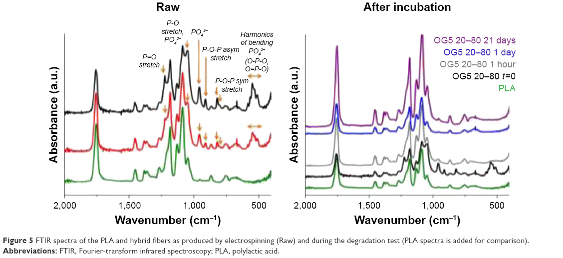 | Figure 5 FTIR spectra of the PLA and hybrid fibers as produced by electrospinning (Raw) and during the degradation test (PLA spectra is added for comparison). |
Calcium dissolution and pH measurements
The dissolution profiles of calcium and the associated pH measurements are displayed in Figure 6. The main changes occurred during the first 2 days. A burst release of calcium was particularly observed immediately after the material immersion. Then, during these 2 days, calcium was released in a less drastic manner. After this time, the material did not seem to release calcium, or in a very low concentration. Regarding the pH of the extracts, it can be noticed that it increased over time. It can be seen, moreover, that the OG5 20–80 fibers released a higher amount of calcium than the OG5 10–90 fibers.
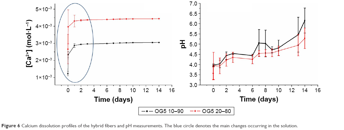 | Figure 6 Calcium dissolution profiles of the hybrid fibers and pH measurements. The blue circle denotes the main changes occurring in the solution. |
Polymer thermal properties
DSC assay was performed to determine whether changes in the polymer occurred along with the material degradation. DSC curves obtained for the hybrid fibers before and after the incubation period are displayed in Figure 7. Table 1 summarizes the evolution of the heat of fusion (ΔHm – melting peak integration) and Tg during the assay. Analysis of curves showed that peaks (ie, bumps) associated with melting processes slightly increased in intensity with incubation time. Values of the ΔHm confirmed these observations. No peak of crystallization was observed for any of the curves. For our hybrids, ΔHc is thus not involved in the calculation of crystallinity. Only ΔHm and Wg variables should be considered when evaluating fiber crystallinity. Determination of the Tg did not reveal any particular trends. The incubation did not seem to affect the glass transition temperature of the materials.
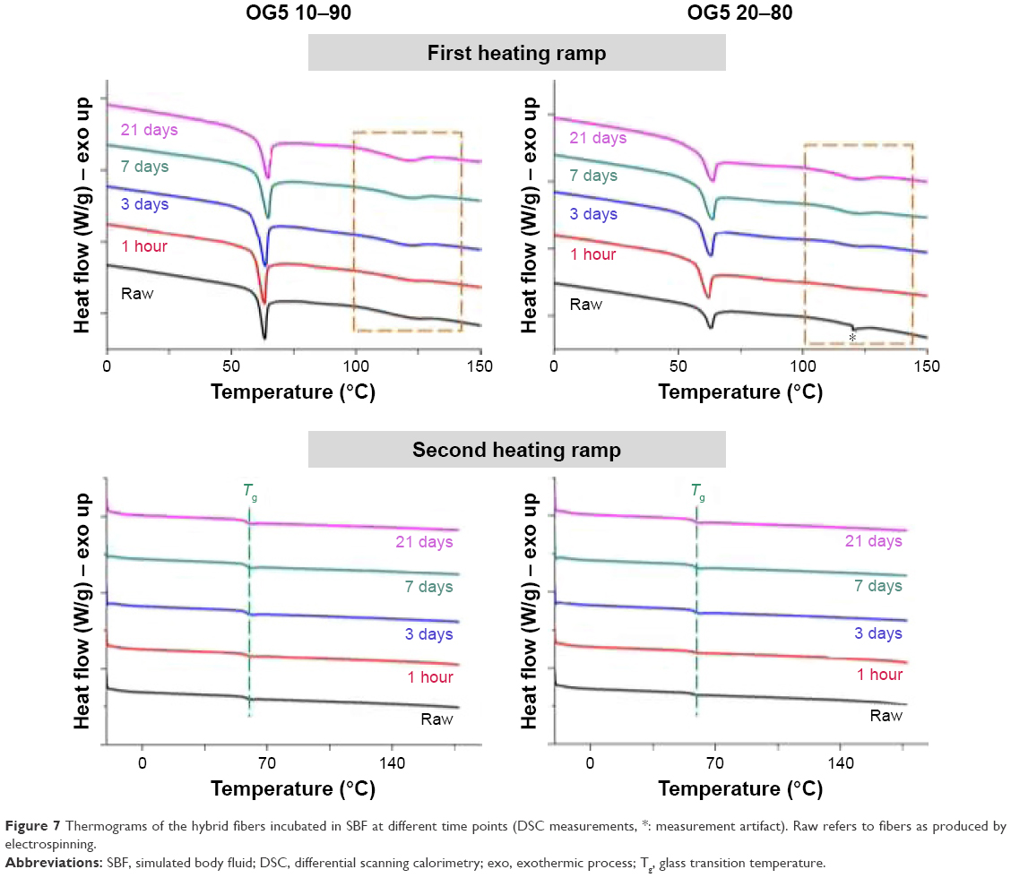 | Figure 7 Thermograms of the hybrid fibers incubated in SBF at different time points (DSC measurements, *: measurement artifact). Raw refers to fibers as produced by electrospinning. |
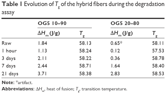 | Table 1 Evolution of Tg of the hybrid fibers during the degradation assay |
Glass loss
The curves obtained by TGA for the fibers, as electrospun and incubated (1 hour and 28 days in SBF), are presented in Figure 8. The remaining weights and calculated glass contents obtained after the thermal treatment are summarized in Table 2. Results showed that the OG5 10–90 and OG5 20–80 fibers, as produced, had an inorganic weight percentage equal to 26.09 and 35.28, respectively. After 1 hour in SBF, fibers lost an important quantity of inorganic phase, especially the OG5 20–80 fibers for which the percentage was reduced by 50%. These fibers had lost a higher quantity of inorganic phase after 1 hour in comparison to the OG5 10–90 fibers which showed a less drastic loss (21%). However, after 1 hour and up to the end of the assay, the OG5 10–90 fibers appeared to be the ones that lost the biggest amount of inorganic part. Equal to 20.56% after 1 hour, the weight percentage indeed dropped to 3.06% for the OG5 10–90 fibers, whereas the OG5 20–80 ones showed a more reasonable decrease (from 16.4% to 8%). After the degradation period (28 days), the OG5 20–80 fibers ended with the higher inorganic weight percentage (around 8% against 3% for the OG5 10–90 fibers).
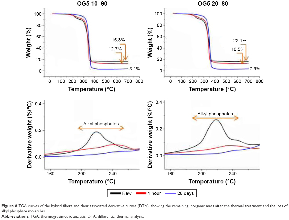 | Figure 8 TGA curves of the hybrid fibers and their associated derivative curves (DTA), showing the remaining inorganic mass after the thermal treatment and the loss of alkyl phosphate molecules. |
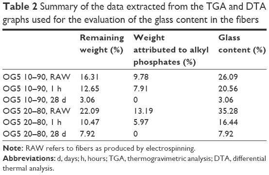 | Table 2 Summary of the data extracted from the TGA and DTA graphs used for the evaluation of the glass content in the fibers |
To obtain more information on the ORMOGLASS loss, particular attention should be given to the alkyl phosphate. The peaks associated to these unreacted alkyl phosphate molecules are, in fact, almost lost after 1 hour and completely disappeared after 28 days. The major weight loss observed at the early stage of immersion is probably due to their fast dissolution.
Glass distribution in the fibers
TEM images revealed that the glass gel was incorporated in the PLA as continuous “bands” distributed along the fiber axis (Figure 9). But, after 21 days of incubation, the PLA phase was less visible, and “granules” and small holes appeared on the pictures. When manipulating the samples, it has been additionally noticed that incubated fibrous layers were more brittle than the ones as obtained by electrospinning. This can be observed on the TEM pictures on the areas where fibers broke. The fracture seemed to happen suddenly without previous elastic deformation (instantaneous breaking). When fibers were immersed in SBF for longer times than the duration of this present study, they actually became extremely fragile up to a critical point where it was not possible to manipulate the scaffold anymore (Figure S3).
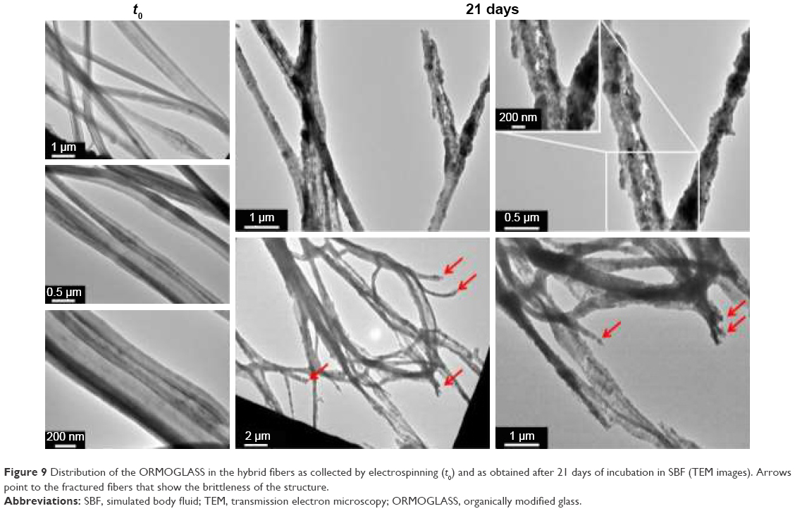 | Figure 9 Distribution of the ORMOGLASS in the hybrid fibers as collected by electrospinning (t0) and as obtained after 21 days of incubation in SBF (TEM images). Arrows point to the fractured fibers that show the brittleness of the structure. |
Discussion
Degradation induces significant changes on fibers throughout the immersion time. The degradation behavior of the novel fibrous PLA–titanium-based ORMOGLASS scaffolds has been studied in terms of morphological, topographical, and chemical modifications. The material was incubated for different periods of time in physiological conditions, and diverse techniques such as FESEM, EDS, TEM, FTIR, and TGA were used to monitor its evolution during immersion in SBF at 37°C.
Degradation of hybrid fibers is fast and seems to be favored by fiber wall stresses. SEM examinations showed that changes in the surface aspect occurred for both the pure polymeric and hybrid fibers (Figures 1 and 2). These changes were however more critical for the hybrid fibers than for the PLA ones. Only tiny wrinkles were seen on the PLA fibers, while structural cracks were additionally noticed on the hybrids. Hybrid fibers also collapsed shortly after their immersion in SBF. The wrinkles of the PLA fibers might be the result of the material degradation process. In nature, the degradation of PLA can be induced, for example, by thermal activation, biological activity (enzymes), oxidation, photolysis, or hydrolysis.34,35 In this study, in which physiological conditions are simulated without the involvement of biological entities and other external factors (temperature, gases), hydrolysis is suggested to be the main phenomenon that can degrade PLA. This process, called hydrolytic degradation, relies on the polymer chain scission that occurs through the nonspecific cleavage of the ester bonds of the main chain.36 In contact with SBF, hydrolytic degradation induced modifications at the fiber surface with time. For the hybrid fibers, the incorporation of the ORMOGLASS significantly affected the degradation profile of the material. The first observed characteristic feature was the collapsing of the fibers. According to the contact angle values reported in the previous studies,14 the hybrid fibers exhibited a high hydrophilicity (contact angle on nonwoven fibers: 82°±2° for the OG5 10–90 and 69°±1° for the OG5 20–80). Thus, SBF can have rapidly infiltrated into the hybrid scaffolds, unlike the pure PLA fibers which were quite hydrophobic14 (contact angle: 133°±4°). This fast fluid infiltration may have applied stress on the fiber walls which in turn made them collapse. Fibers produced by electrospinning as hollow structures due to the Kirkendall effect10,37 may have not supported this force and become flattened. As a consequence, cracks might have sometimes formed because of this sudden fiber structural change. The fast fluid infiltration can be also an explanation for the slow opening of the fibers. If fibers did not instantaneously fracture by cracking, the change of fiber structure might have led to other stresses perpendicularly applied to the axis which may tend to slowly open the fibers. This process may have been also amplified by the presence of the crack itself. A crack introduced “weaknesses” on the fiber walls, which could have acted as the starting point of this fiber opening process. A schematic representation of these possible processes can be seen in Figure S4. Another phenomenon that could explain the formation of cracks could be an increase of crystallinity in the material during the incubation. In fact, when materials become more crystalline, the rearrangement of the polymer chains leads to the formation of spaces with low chain density and possibly facilitates the appearance of cracks. DSC results demonstrated that the ΔHm of the hybrid fibers increased with the incubation time (Figure 7; Table 1). In a pure polymeric sample, this would have suggested that more crystalline phase was present in the fibers. But, in the case of hybrid samples, the percentage of the polymer crystallinity depends on the amount of inorganic phase present in the materials. Considering the usual equation for crystallinity determination, the percentage of crystallinity in our hybrids is calculated by dividing ΔHm by a factor lower than one (calculated considering the percentage of the inorganic compounds in the studied material). The lower the amount of the inorganic phase, the higher this factor, and consequently, the lower the value of the quotient. In our case, the ORMOGLASS dissolved during the incubation. This means that the fibers, after 21-day incubation, contained less ORMOGLASS than the ones after 3 days, for example. Thus, for the 21-day fibers, the ΔHm is divided by a higher factor than for the 3-day fibers. As a result, ΔHm is more significantly lowered by the ORMOGLASS content for the 21-day fibers than for the 3-day fibers. In other words, these mathematical considerations mean that for our study, an increase in ΔHm does not demonstrate an increase in crystallinity. It is possible that the higher ΔHm value of the 21-day fibers was “compensated” by the introduction of the low value of the ORMOGLASS content for the determination of the crystallinity. Unfortunately, it was not possible to precisely calculate ΔHm and the crystallinity of the fibers during this degradation study because the weight of ORMOGLASS was different and unknown for each time point after t0. TGA assays is a useful supporting technique to obtain this information, but after the assays, insufficient amount of sample for such destructive tests remained. Complementary X-ray diffraction (XRD) measurements were however performed to verify whether the crystallinity was indeed increased (Figure S5). As no crystalline peaks were seen on the XRD spectra, it was assumed that the incubation did not increase the crystallinity of the polymeric constituent of the fibers (or at least, not above the detection limit of the technique). For this reason, crystallinity was considered not involved in the formation of cracks. Therefore, the hypothesis that stress on the fiber walls caused the defects was favored.
In addition, acidic pH caused by the presence of the ORMOGLASS promoted the degradation of the polymeric phase.38 The hydrolyzed fragments may be removed from the surface and released in the SBF, which would explain the observation of holes on the FESEM and TEM pictures (Figures 2 and 9). The AFM analysis confirmed that the morphological changes resulted in topographical modifications (Figure 3). It demonstrated, for example, how the opening of the fibers induced a slight decrease in the height profile in the middle of their width and how the roughness of the fibers increased after the degradation period.
Most changes, which are critical to obtain an efficient calcium-rich environment, occurred during the first day of incubation. According to results shown in Figure 4, a high decrease in the calcium content was observed after the first hour while the phosphate amount continued decreasing till the first day, reaching levels that were previously described as angiogenic promoters. The dissolution of a high amount of calcium just after the material immersion was also confirmed by the calcium release assay (Figure S1). The increase of calcium observed between the first hour and the first day on the EDS measurements should be interpreted as a result of the phosphate decrease and not as gain of calcium on the fibers, considering percentages as relative values. This is what happened for the calcium and also for the titanium content, which increased significantly because of a decrease in both phosphate and calcium. After 3 days and up to 21 days, the composition of the fibers stabilized. This suggested that the degradation of the glass phase occurred in a homogeneous manner in terms of chemical molar ratios. This result is in accordance with a study performed by Navarro et al on different titanium-based glasses that revealed a stable Ca/P2 ratio after the first hours of incubation of micrometric glasses and a quasi-stable ionic release during their slow dissolution.39 However, the composition of the fibers after 3 days differs from the original OG5 one, as a lot of phosphate and calcium are lost at the initial stage of immersion. In relation to the previous cellular assays reported,14 this means that the angiogenic calcium concentration (between 3 and 10 mM)40 is reached during the first day of sample immersion. Applications strongly depend on at what point angiogenic processes are needed in the different steps of tissue repair; however, it is known that angiogenesis is always required during the early stages of bone healing.41
Phosphorus species are also released very fast, and they affect the pH. FTIR analysis showed that the infrared spectra of the hybrid fibers after their deposition by electrospinning exhibited the characteristic absorbance peaks of PLA and additional signals related to phosphate complexes (Figure 5). The PO43− tetrahedron, the basic building block of phosphate-based glasses,28,42 is present in the fibers, as represented by the absorbance observed at numerous wavelengths. P–O–P stretching modes are also clearly visible on the spectrum. The presence of these signals is attributed to the P–O–P bonds involved in the glass-forming network. The P=O bonds on the contrary did not contribute to the ORMOGLASS network creation due to their chemical stability. After 1 hour in SBF, phosphate signals almost disappeared, because an important quantity of phosphate was dissolved in this short time. Only a very slight shoulder between 580 and 450 cm−1 can attest to a small remaining amount of phosphate. But after 1 day, no signals from phosphate were noticed anymore. This is in accordance with EDS results: the dissolution of phosphates started as soon as the material was in contact with fluid and continued during the first day. In parallel to the calcium, the fibers seemed therefore to undergo a strong burst release of phosphates. The pH is then affected as P is hydrolyzed and forms H3PO4, being probably the cause of the initial acidic pH of the fibers when immersed in pure water (Figure S1). Modifications are required to strongly link alkyl phosphate.
TGA measurements were performed to quantify ORMOGLASS loss. The decrease of the inorganic content weight which immediately dropped after 1-hour immersion in SBF confirmed that for both OG5 10–90 and OG5 20–80 fibers, a significant amount of ORMOGLASS was dissolved after this time (Figure 8; Table 2). As mentioned before, the produced fibers contained a high amount of unreacted alkyl phosphates. It was suggested that part of the monoethyl- and diethyl-phosphate molecules contained in the ORMOGLASS precursor mix did not fully react to form the ORMOGLASS network, or the reaction formed a very weak bond with the other species. According to the weight loss associated to alkyl phosphates, it is clear that a certain amount of phosphate was not effectively incorporated and was rather found as free molecules in the ORMOGLASS gel (ie, fibers). As a consequence, it can easily be released in SBF. This could partially explain the results obtained by EDS, FTIR, and TGA after 1 hour of immersion. However, even if only the loss of phosphate is observed on TGA thermograms, it should be stated that the diminution of the starting glass weight percentage was also due to the initial calcium release revealed by EDS measurements and the calcium release assay (Figures 4 and 6). In other words, it means that the amount of ORMOGLASS in the fibers was not exactly that determined by the TGA; the values should be a little bit higher. It is certain that organic fragments of the ORMOGLASS degraded during the assay, even if they were not revealed by TGA (probably under the detection limit or masked by other signals). In conclusion, TGA can give an idea of the amount of ORMOGLASS contained in the fibers, but it did not provide accurate values, unlike for other composites that contained a fully inorganic phase.43 After 28 days, no alkyl phosphate peaks were observed in the hybrid fibers (no peaks on the thermograms). Based on FTIR and EDS observations, this dissolution seemed, in fact, to have been already completely reached after the first day. This is why, after 3 days and up to the end of the assay, the composition of the fibers showed fewer critical changes than at early stages of immersion. Once the excess of nonreacted compounds and a certain amount of glass gel had been released, the molar ratio stabilized and the glass maintained the same composition during its degradation. At the end of the assay, small amounts of inorganic material were found in the fibers in comparison to their initial content. Considering that titanium-based inorganic glasses degrade slowly because of the presence of titanium in the glass network, a valid conclusion would be that the changes in weight were mainly due to the fast initial dissolution described above. This slow degradation behavior has been shown for micrometric solid bulk glasses.39 Here, several factors may have promoted a faster degradation of the ORMOGLASS: the organometallic “gel” state of the ORMOGLASS and its relative weak cohesion compared with a conventional inorganic glass; the high surface-to-volume ratio of the scaffold; and its high hydrophilicity. Fast dissolution and subsequent degradation were therefore finally suggested to be both involved in the global weight changes determined by TGA.
Experimental changes can be performed to enhance glass release efficiency. Concerning in particular the critical high weight loss at the beginning of the assay, a similar behavior has been identified for other composites made of PLA and the same glass composition. Prepared by the solvent casting–sol leaching method, these materials demonstrated a significant weight loss after the first week of immersion in SBF.29 This was attributed to some morphological modifications and degradation of glass particles. The fact that, in our case, the fast dissolution was already over after a few hours confirmed that this release might mainly be due to the release of residual compounds not involved in the ORMOGLASS structure and part of the ORMOGLASS gel. PLA and ORMOGLASS degradation was indeed not expected to happen in such a short time. To minimize or avoid this burst release, a better control of the ORMOGLASS network formation could be further performed in order to enhance the efficiency of the hydrolysis and thus obtain a better incorporation of calcium and phosphate. Changes in the catalyst or hydrolysis duration or precursor’s reactivity could be assessed, for example. If more calcium and phosphate reacted with the other reagents, a less drastic immediate release would be expected. However, OG5 corresponds to a glass that contains a high amount of calcium and phosphate. It is therefore not easy to find the experimental conditions that induce an optimal hydrolysis of the compounds and therefore an efficient reactivity to form the glass network. We have considered that, as a network modifier, calcium only links two chains and phosphate a maximum of three. Titanium has four ligands, so it can form a better network. However, its concentration is quite low and the idea is not to increase it. Precise investigations involving nuclear magnetic resonance (NMR), for example, should be further performed to accurately define the hydrolysis parameters and optimization of ORMOGLASS gels.
ORMOGLASS and the polymer are not homogeneously blended, and this exposes the organometallic directly to the aqueous media. The interaction between the ORMOGLASS and the polymer should be tuned to control the initial burst release.44 As seen on TEM images, the ORMOGLASS and the polymer did not mix homogeneously when preparing the blends for electrospinning (Figure 9). ORMOGLASS “bands” were observed in the produced fibers independent from the polymeric phase. This may explain the DSC results obtained in the previous studies14 in which no significant differences in the Tg were reported for the PLA and hybrid fibers. Because the polymer did not properly interpenetrate with the ORMOGLASS, the mobility of the PLA chains was not affected. It is inferred that if better interactions between the phase are achieved, an increase in Tg could be expected due to the diminution of flexibility and motility of the polymer chains, their intermolecular interactions with the ORMOGLASS, and the steric effect applied by the ORMOGLASS.45 It is thus believed that Tg remained quasi-unchanged, not only because the fibers are a class-I hybrid material, but also because the phases are not homogeneously blended. Even though considered as not significant, the very slight decreases of Tg observed after incorporation of the ORMOGLASS may suggest that the presence of the ORMOGLASS however affected Tg to a very low extent. As observed for some composites,29,46 one hypothesis could be that the ORMOGLASS slightly decreased the molecular weight of the PLA, favoring thus the glass transition at lower temperature. Nevertheless, as the differences are too low, this speculation leads to a vague conclusion, and more investigations are required in order to clearly determine the real effect of the ORMOGLASS on the thermal properties of the PLA in the hybrids. What seems to be clear, unlike in the study performed by Navarro et al, the fibers here did not undergo changes in Tg during the degradation assay,29 probably because of this nonhomogeneous dispersion of the glass in the polymer matrix.
Long immersion times induce an extreme fragility in the material. After 21 days, granule-like structures were observed inside the fibers and the ORMOGLASS bands lost their continuity during fiber degradation. Such granules are typically observed when titanium-based materials are assessed under TEM.47–49 The loss of glass continuity is attributed to the drastic loss of compounds occurring just after the material immersion and the progressive dissolution of the glass remaining in the fibers. Moreover, holes were also observed on FESEM and TEM pictures, attesting that the compounds partially degraded. It has also been observed that throughout the incubation of the material, the fibers became more and more brittle, whereas the mats were fully flexible before incubation. In hybrid bioactive materials, the inorganic phase promotes the bioactivity of the scaffold and the organic one supports the mechanical properties.4 It is thus hypothesized that in the case of the incubated fibers, PLA reached a critical point of degradation where it was not able to fulfill its function anymore. On the TEM pictures, the fragility of the scaffold is particularly evident. Moreover, the material “defects” enumerated previously (holes, cracks, opened fibers) surely introduced weaknesses in the structure, which might have directly led to the decrease in the mechanical properties of the scaffold. Combined with the granule-like structures, which did not seem to have a proper cohesion between themselves (discontinuity), all these morphological and structural modifications might have contributed to the low resistance of the material to cause it to collapse and decrease in toughness.
Degradation of the ORMOGLASS seems to increase the hydrolysis of PLA. The degradation period of this study was rather short in comparison to some other in vitro degradation investigations reported in the literature.50,51 However, the scaffolds presented here significantly degraded in 4 weeks, and there was no reason for a longer incubation time, especially because of the brittleness of the material and the difficulties in handling it. It was evident that a lot of the glass gel is lost during the initial dissolution and its subsequent degradation. It was also clear on the TEM pictures that part of the polymeric phase was degraded. In fact, during the degradation of composites, the dissolution of each constituent influences the dissolution of the other phases. As explained previously, PLA resorbs following a hydrolytic degradation mechanism. The cleavage of the ester bonds leads to the formation of carboxylic (and hydroxyl) groups creating an acidic environment. This change in pH can catalyze the scission of more PLA chains (autocatalysis) but also favors the dissolution of the ORMOGLASS.24,29 On the other hand, the dissolution of the ORMOGLASS can also accelerate the PLA degradation by modifying as well the pH of the surrounding fluid.52 It has been demonstrated that when the same OG5 composition glass is added to PLA, the molecular weight of the polymer is reduced.29 The PLA used in our study was especially exposed to degradation as it was completely amorphous (no crystalline peaks detected by XRD–Figure S5). Amorphization is one of the inherent characteristics of electrospinning due to the sudden evaporation of the solvent; this does not allow the slow equilibrium rearrangement of the chains that probably happens when commercial raw material is produced.53,54 In addition, when combining L and D copolymers, crystallization also tends to decrease compared to pure L-PLA, resulting in a completely amorphous fiber.9,10 The degradation processes of both phases are therefore closely related and the material resorption cannot be fully interpreted following the degradation of the individual compounds. Moreover, the interplay of different factors such as hydrophilicity, fluid infiltration, scaffold structure (fibers thinness), porosity, specific surface, and interconnectivity additionally complicate the understanding of the degradation mechanism of hybrids and materials in general.34,55,56 In in vivo conditions, other biological parameters will influence the material resorption as well (cell–material interactions, dynamic flow of body fluid, enzyme activity, etc.) and consequently altered the scaffold integrity in a different way than that reported here.
Hybrid materials in this study did not promote calcium phosphate deposition. In contrast, they release a feasible amount of calcium ions to trigger specific angiogenic responses. Studies involving bioactive (mainly silicon-based) glasses often report the precipitation of calcium phosphate on the surface of the scaffold after incubation in SBF. Here, the SBF incubation did not promote the deposition of such compounds, even it is a metastable solution designed for phosphate precipitation onto bioactive surfaces. It is assumed that the fast dissolution of the glass at the beginning of the immersion seemed to avoid any possibility of stable precipitation. Also, according to Lucacel et al, the presence of titanium in the glass network (TiO2) inhibits the formation of apatite type layer.26 It is believed that titanium-based glasses decrease the bioactivity of calcium phosphate samples because of their slow dissolution rate. These ORMOGLASSES, however, favor cell attachment, proliferation, and differentiation.42 It is thus already commonly accepted that such bioactive glasses should rather be used with cells than for an efficient mineralization.42,57 In fact, Monem et al demonstrated that it is not necessary to require a chemical link between calcium phosphate compounds and the host tissue, because other variables of the material may also promote bone growth.58 Novel fibrous mats described in this study are aimed to be used as substrates for the triggering of specific cellular activity either in cellular or in acellular tissue engineering approaches, and not to be used for improving implant integration.
Regarding the possible clinical application of this scaffold, improvements should be made to the ORMOGLASS preparation and on the organic-inorganic interactions in order to modulate the initial fast dissolution that occurs on the first day, depending on the application. The degradation of the scaffold was rather fast according to the morphological changes observed. For bone regeneration, however, templates that exhibit a slower degradation are usually preferred, so that the graft degrades at a speed that matches the gradual formation of natural bone. According to this assay, our fibers did not seem appropriate for long-term applications, but two things should be kept in mind: first, that the degradation behavior of a material generally differs between in vitro and in vivo assays and that its resorption rate might be reduced by the dynamic flow of the body fluid (removal of the acidic species); and second, no universal bone substitute exists as yet and, as such, this material would be an excellent option for angiogenic guided bone healing, for example, in periosteum membrane regeneration for initial bone ingrowth.59
Conclusion
The in vitro degradation of PLA–OG5 fibrous scaffolds has been assessed in simulated physiological conditions. This study revealed that the material resorption was first characterized by a burst release of calcium and phosphate at the beginning of the incubation, followed by a continuous PLA and ORMOGLASS degradation until the end of the assay. The concentration of the calcium release reaches ranges that are described as angiogenic by previous studies (~3–10 mM). The fibers maintained a stable molar ratio over the incubation period, which suggested that the ORMOGLASS dissolved homogeneously over time in terms of chemical composition. However, due to the high dissolution rate of the ORMOGLASS at the early stage of the immersion, the fibers did not possess the exact OG5 composition during this assay. Guiding bone regeneration seems to be the best option for the application of these constructs. However, further investigations on the ORMOGLASS preparation (improvement of hydrolysis efficiency), constituent interactions (homogeneous blending and creation of strong chemical bonding), and in vivo studies should be additionally performed to assess the real effective potential of PLA-OG5 ORMOGLASS fibers for bone tissue engineering applications.
Acknowledgments
The authors thank the European Commission (European ERANET project PI11/03030, NANGIOFRAC), the Spanish Ministry of Economy and Competitiveness (Project MAT2011-29778-C02-01), and the National Center for Research and Development (contract No 04/Euronanomed/2012) for funding. O Castaño also acknowledges the MINECO for the “Ramon y Cajal”, I3 program and the support from the Serra Húnter Programme. N Sachot thanks AGAUR (travel grant fellowship) for its financial support. We also thank Dr Tomasz Brynk, Tomasz Jaroszewicz, Ewa Kijeńska, Emilia Choińska, Piotr Borychowski, Marcin Rasinski, and Gerard Oncins for their help with SEM, EDS, TEM, and AFM devices.
Disclosure
The authors report no conflicts of interest in this work.
References
Perán M, García MA, López-Ruiz E, et al. Functionalized Nanostructures with Application in Regenerative Medicine. Int J Mol Sci. 2012;13(3):3847–3886. | ||
Navarro M, Michiardi A, Castaño O, Planell JA. Biomaterials in orthopaedics. J R Soc Interface. 2008;5(27):1137–1158. | ||
Place ES, Evans ND, Stevens MM. Complexity in biomaterials for tissue engineering. Nat Mater. 2009;8(6):457–470. | ||
Sachot N, Engel E, Castaño O. Hybrid organic–inorganic scaffolding biomaterials for regenerative therapies. Curr Org Chem. 2014;18(18):2299–2314. | ||
Dziadek M, Pawlik J, Menaszek E, Stodolak-Zych E, Cholewa-Kowalska K. Effect of the preparation methods on architecture, crystallinity, hydrolytic degradation, bioactivity, and biocompatibility of PCL/bioglass composite scaffolds. J Biomed Mater Res B Appl Biomater. 2015;103(8):1580–1593. | ||
Sanzana ES, Navarro M, Ginebra M-P, Planell JA, Ojeda AC, Montecinos HA. Role of porosity and pore architecture in the in vivo bone regeneration capacity of biodegradable glass scaffolds. J Biomed Mater Res A. 2013;102(6):1767–1773. | ||
Castaño O, Sachot N, Xuriguera E, et al. Angiogenesis in bone regeneration: tailored calcium release in hybrid fibrous scaffolds. ACS Appl Mater Interfaces. 2014;6(10):7512–7522. | ||
Poh PSP, Hutmacher DW, Stevens MM, Woodruff MA. Fabrication and in vitro characterization of bioactive glass composite scaffolds for bone regeneration. Biofabrication. 2013;5(4):45005. | ||
Álvarez Z, Mateos-Timoneda MA, Hyroššová P, et al. The effect of the composition of PLA films and lactate release on glial and neuronal maturation and the maintenance of the neuronal progenitor niche. Biomaterials. 2013;34(9):2221–2233. | ||
Álvarez Z, Castaño O, Castells AA, et al. Neurogenesis and vascularization of the damaged brain using a lactate-releasing biomimetic scaffold. Biomaterials. 2014;35(17):4769–4781. | ||
Yildirimer L, Seifalian AM. Three-dimensional biomaterial degradation – material choice, design and extrinsic factor considerations. Biotechnol Adv. 2014;32(5):984–999. | ||
Sun M, Kingham PJ, Reid AJ, Armstrong SJ, Terenghi G, Downes S. In vitro and in vivo testing of novel ultrathin PCL and PCL/PLA blend films as peripheral nerve conduit. J Biomed Mater Res A. 2010;93(4):1470–1481. | ||
Krishnan V, Lakshmi T. Bioglass: a novel biocompatible innovation. J Adv Pharm Technol Res. 2013;4(2):78–83. | ||
Sachot N, Castaño O, Oliveira H, et al. A novel hybrid nanofibrous strategy to target progenitor cells for cost-effective in situ angiogenesis. J Mater Chem B. 2016;4(43):6967–6978. | ||
Kraehenbuehl TP, Langer R, Ferreira LS. Three-dimensional biomaterials for the study of human pluripotent stem cells. Nat Methods. 2011;8(9):731–736. | ||
Mager MD, LaPointe V, Stevens MM. Exploring and exploiting chemistry at the cell surface. Nat Chem. 2011;3(8):582–589. | ||
Jang J-H, Castano O, Kim H-W. Electrospun materials as potential platforms for bone tissue engineering. Adv Drug Deliv Rev. 2009;61(12):1065–1083. | ||
Yu D-G, Yang C, Jin M, et al. Medicated Janus fibers fabricated using a Teflon-coated side-by-side spinneret. Colloids Surf B Biointerfaces. 2016;138:110–116. | ||
Yang G-Z, Li J-J, Yu D-G, He M-F, Yang J-H, Williams GR. Nanosized sustained-release drug depots fabricated using modified tri-axial electrospinning. Acta Biomater. 2017;53:233–241. | ||
Oyane A, Kim H-M, Furuya T, Kokubo T, Miyazaki T, Nakamura T. Preparation and assessment of revised simulated body fluids. J Biomed Mater Res Part A. 2003;65A(2):188–195. | ||
Kokubo T, Takadama H. How useful is SBF in predicting in vivo bone bioactivity? Biomaterials. 2006;27(15):2907–2915. | ||
Chow WS, Lok SK. Thermal properties of poly(lactic acid)/organo-montmorillonite nanocomposites. J Therm Anal Calorim. 2009;95(2):627–632. | ||
Lee TH, Boey FYC, Khor KA. On the determination of polymer crystallinity for a thermoplastic PPS composite by thermal analysis. Compos Sci Technol. 1995;53:259–274. | ||
Henton DE, Gruber P, Lunt J, Randall J. Polylactic acid technology. In: Natural Fibers, Biopolymers and Biocomposites. Misra M, Drzal LT, editors. Boca Raton: CRC Press; 2005:527–578. | ||
Ng S, Guo J, Ma J, Loo SCJ. Synthesis of high surface area mesostructured calcium phosphate particles. Acta Biomater. 2010;6(9):3772–3781. | ||
Lucacel RC, Maier M, Simon V. Structural and in vitro characterization of TiO2-CaO-P2O5 bioglasses. J Non Cryst Solids. 2010;356(50–51):2869–2874. | ||
Schrotter J, Cardenas A, Smaihi M, Hovnanian N. Silicon and phosphorus alkoxide mixture: sol-gel study by spectroscopic technics. J Sol-Gel Sci Technol. 1995;4:195–204. | ||
Dayanand C, Bhikshamaiah G, Jaya Tyagaraju V, Salagram M, Krishna Murthy ASR. Structural investigations of phosphate glasses: a detailed infrared study of the x(PbO)–(1–x)P2O5, vitreous system. J Mater Sci. 1996;31:1945–1967. | ||
Navarro M, Ginebra MP, Planell JA, Barrias CC, Barbosa MA. In vitro degradation behavior of a novel bioresorbable composite material based on PLA and a soluble CaP glass. Acta Biomater. 2005;1(4):411–419. | ||
Pryce RS, Hench LL. Tailoring of bioactive glasses for the release of nitric oxide as an osteogenic stimulus. J Mater Chem. 2004;14(14):2303. | ||
Radev L, Hristov V, Michailova I, Samuneva B. Sol–gel bioactive glass–ceramics Part II: Glass–ceramics in the CaO–SiO2–P2O5–MgO system. Cent Eur J Chem. 2009;7(3):322–327. | ||
ElBatal HA, Khalil EMA, Hamdy YM. In vitro behavior of bioactive phosphate glass–ceramics from the system P2O5–Na2O–CaO containing titania. Ceram Int. 2009;35(3):1195–1204. | ||
Aguiar H, Serra J, González P, León B. Structural study of sol–gel silicate glasses by IR and Raman spectroscopies. J Non Cryst Solids. 2009;355(8):475–480. | ||
Yew GH, Mohd Yusof AM, Mohd Ishak ZA, Ishiaku US. Water absorption and enzymatic degradation of poly(lactic acid)/rice starch composites. Polym Degrad Stab. 2005;90(3):488–500. | ||
Mochizuki M, Hirami M. Structural effects on the biodegradation of aliphatic polyesters. Polym Adv Technol. 1997;8:203–209. | ||
Li S. Hydrolytic degradation characteristics of aliphatic polyesters derived from lactic and glycolic acids. J Biomed Mater Res. 1999;48(3):342–353. | ||
Fan HJ, Gösele U, Zacharias M. Formation of nanotubes and hollow nanoparticles based on Kirkendall and diffusion processes: a review. Small. 2007;3(10):1660–1671. | ||
Lee W, Gardella JA. Hydrolytic kinetics of biodegradable polyester monolayers. Langmuir. 2000;16:3401–3406. | ||
Navarro M, Ginebra M, Clément J, Martinez S, Avila G, Planell JA. Physicochemical degradation of titania-stabilized soluble phosphate glasses for medical applications. J Am Ceram Soc. 2003;86(8):1342–1352. | ||
Aguirre A, González A, Planell JA, Engel E. Extracellular calcium modulates in vitro bone marrow-derived Flk-1+ CD34+ progenitor cell chemotaxis and differentiation through a calcium-sensing receptor. Biochem Biophys Res Commun. 2010;393(1):156–161. | ||
Stegen S, van Gastel N, Carmeliet G. Bringing new life to damaged bone: the importance of angiogenesis in bone repair and regeneration. Bone. 2015;70:19–27. | ||
Kiani A, Lakhkar NJ, Salih V, et al. Titanium-containing bioactive phosphate glasses. Philos Trans R Soc Ser A, Math Phys Eng Sci. 2012;370(1963):1352–1375. | ||
Patlolla A, Collins G, Arinzeh TL. Solvent-dependent properties of electrospun fibrous composites for bone tissue regeneration. Acta Biomater. 2010;6(1):90–101. | ||
Jones JR. New trends in bioactive scaffolds: the importance of nanostructure. J Eur Ceram Soc. 2009;29(7):1275–1281. | ||
Lee JH, Park TG, Park HS, et al. Thermal and mechanical characteristics of poly(l-lactic acid) nanocomposite scaffold. Biomaterials. 2003;24(16):2773–2778. | ||
Pluta M. Melt compounding of polylactide/organoclay: structure and properties of nanocomposites. J Polym Sci Part B Polym Phys. 2006;44:3392–3405. | ||
Caruso RA, Schattka JH, Greiner A. Titanium dioxide tubes from sol-gel coating of electrospun polymer fibers. Adv Mater. 2001;13(20):1577–1579. | ||
Chang G, Zheng X, Chen R, Chen X, Chen L, Chen Z. Silver nanoparticles filling in TiO2 hollow nanofibers by coaxial electrospinning. Acta Physico-Chimica Sin. 2008;24(10):1790–1796. | ||
Li D, Xia Y. Electrospinning of nanofibers: reinventing the wheel? Adv Mater. 2004;16(14):1151–1170. | ||
Chouzouri G, Xanthos M. In vitro bioactivity and degradation of polycaprolactone composites containing silicate fillers. Acta Biomater. 2007;3(5):745–756. | ||
Blaker JJ, Nazhat SN, Maquet V, Boccaccini AR. Long-term in vitro degradation of PDLLA/bioglass bone scaffolds in acellular simulated body fluid. Acta Biomater. 2011;7(2):829–840. | ||
Li H, Chang J. pH-compensation effect of bioactive inorganic fillers on the degradation of PLGA. Compos Sci Technol. 2005;65(14):2226–2232. | ||
Wang C, Chien H-S, Yan K-W, et al. Correlation between processing parameters and microstructure of electrospun poly(D,L-lactic acid) nanofibers. Polymer (Guildf). 2009;50(25):6100–6110. | ||
Pretula J, Slomkowski S, Penczek S. Polylactides – methods of synthesis and characterization. Adv Drug Deliv Rev. 2016;107:3–16. | ||
Choueka J, Charvet JL, Alexander H, et al. Effect of annealing temperature on the degradation of reinforcing fibers for absorbable implants. J Biomed Mater Res. 1995;29:1309–1315. | ||
Cao Y, Mitchell G, Messina A, et al. The influence of architecture on degradation and tissue ingrowth into three-dimensional poly(lactic-co-glycolic acid) scaffolds in vitro and in vivo. Biomaterials. 2006;27(14):2854–2864. | ||
Abou Neel EA, Mizoguchi T, Ito M, Bitar M, Salih V, Knowles JC. In vitro bioactivity and gene expression by cells cultured on titanium dioxide doped phosphate-based glasses. Biomaterials. 2007;28(19):2967–2977. | ||
Monem AS, ElBatal HA, Khalil EMA, Azooz MA, Hamdy YM. In vivo behavior of bioactive phosphate glass–ceramics from the system P2O5–Na2O–CaO containing TiO2. J Mater Sci Mater Med. 2008;19(3):1097–1108. | ||
Rajzer I, Menaszek E, Kwiatkowski R, Planell JA, Castano O. Electrospun gelatin/poly(ε-caprolactone) fibrous scaffold modified with calcium phosphate for bone tissue engineering. Mater Sci Eng C. 2014;44:183–190. |
Supplementary materials
Calcium dissolution and pH measurements
The assessment of ion dissolution by materials is often carried out in simulated body fluid (SBF) or in culture medium.1 Performing such assays in these solutions is interesting as it enables determination of the changes in ion concentration closely, as they occur in in vitro and in vivo tests. However, these solutions act as buffers and can prevent these modifications being clearly seen. Therefore, to assess precisely the ion-release behavior, it is more appropriate to use deionized water as it does not temper the effects of the ion release. A study performed with the hybrid fibers incubated in water and in SBF demonstrated these affirmations (Figure S1). While the difference in calcium concentration and release rate was obvious in water, it was difficult to observe in SBF. The pH changes were also less important in SBF than in water. Moreover, the supply of calcium ion from the SBF rapidly masked the slight changes caused by the material. Differences in ion-release profiles were also observed by other researchers when the studied materials were immersed in different solutions.2
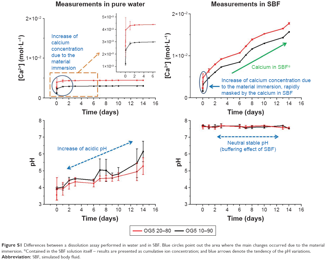 | Figure S1 Differences between a dissolution assay performed in water and in SBF. Blue circles point out the area where the main changes occurred due to the material immersion. *Contained in the SBF solution itself – results are presented as cumulative ion concentration; and blue arrows denote the tendency of the pH variations. |
Fiber morphology
Additional pictures of the fiber morphology are shown in Figure S2. These images demonstrated a good correlation between images obtained by field-emission scanning electron microscopy (FESEM) and the ones obtained by atomic force microscopy (AFM). All the typical fiber defects that occurred during the material incubation were seen with both techniques.
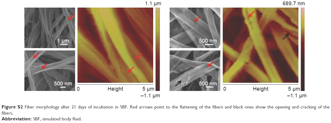 | Figure S2 Fiber morphology after 21 days of incubation in SBF. Red arrows point to the flattening of the fibers and black ones show the opening and cracking of the fibers. |
Scaffold integrity
When hybrid fibers were incubated in SBF, they became extremely brittle with time. At some point, it was even impossible to handle the mats (Figure S3).
 | Figure S3 Pictures of the hybrid fibers after several weeks of incubation in SBF. |
Fiber flattening and defects
As represented in Figure S4, when water infiltrated the fibers, the water may have originated zones of high strain on the fiber walls due to the fiber flattening (hollow fibers). To release this strain, fibers may have cracked instantaneously (Path 1). Another possibility could be that fibers did not crack immediately and that the flattening led to additional forces applied perpendicularly to the fiber length. Consequently, fibers may have slowly opened in the middle of the fibers (Path 2). The last explanation may be that the presence of the crack may have itself induced the opening on the fibers by introducing other forces on each side of the crack (Path 3). These three options might explain the images of the different defects observed during the fiber degradation.
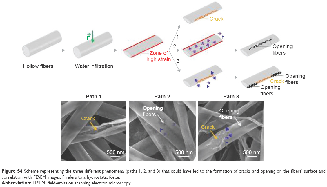 | Figure S4 Scheme representing the three different phenomena (paths 1, 2, and 3) that could have led to the formation of cracks and opening on the fibers’ surface and correlation with FESEM images. F refers to a hydrostatic force. |
Fiber crystallinity
Because it was not possible, using differential scanning calorimetry, to define if the crystallinity of the fibers increased along with the incubation, X-ray measurements were carried out as complementary tests with the T5 20–80 fibers. Polylactic acid (PLA) pellets and PLA fibers were used as controls. The measurements were conducted using a PANalytical X’Pert PRO MPD diffractometer and measuring from 2 to 30° (2θ) at a wavelength of CuKα λ=1.5406Å. Results are reported in Figure S5. As seen on the spectra, crystalline phases were detected on the hybrid fibers, as produced by electrospinning. According to the literature3,4 and the “International Center for Diffraction Data” XRay database (PCPDFWIN software), the associated peaks may correspond to hydrated titanium–phosphate species, containing, or not, sodium (eg, Ti(HPO4)2·2H2O, Na2Ti(PO4)·4H2O, and other possible species). After 1-hour immersion, these peaks disappeared, suggesting that these compounds were dissolved in the SBF. Also, it was hypothesized that these compounds were present in a small quantity in comparison to the total amount of ORMOGLASS and were considered as “residual” species. After 1-hour immersion and up to the end of the assay, fibers did not seem to crystallize. All the samples appeared to be amorphous. This attested that the incubation did not favor the crystallization of the compounds in the fibers (or at least, not enough to be detected). As a consequence, it is highly probable that crystallinity did not cause the formation of cracks on the fibers.
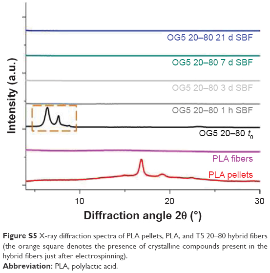 | Figure S5 X-ray diffraction spectra of PLA pellets, PLA, and T5 20–80 hybrid fibers (the orange square denotes the presence of crystalline compounds present in the hybrid fibers just after electrospinning). |
References
Perán M, García MA, López-Ruiz E, et al. Functionalized Nanostructures with Application in Regenerative Medicine. Int J Mol Sci. 2012;13(3):3847–3886. | ||
Navarro M, Michiardi A, Castaño O, Planell JA. Biomaterials in orthopaedics. J R Soc Interface. 2008;5(27):1137–1158. | ||
Place ES, Evans ND, Stevens MM. Complexity in biomaterials for tissue engineering. Nat Mater. 2009;8(6):457–470. | ||
Sachot N, Engel E, Castaño O. Hybrid organic–inorganic scaffolding biomaterials for regenerative therapies. Curr Org Chem. 2014;18(18):2299–2314. |
 © 2017 The Author(s). This work is published and licensed by Dove Medical Press Limited. The
full terms of this license are available at https://www.dovepress.com/terms
and incorporate the Creative Commons Attribution
- Non Commercial (unported, 3.0) License.
By accessing the work you hereby accept the Terms. Non-commercial uses of the work are permitted
without any further permission from Dove Medical Press Limited, provided the work is properly
attributed. For permission for commercial use of this work, please see paragraphs 4.2 and 5 of our Terms.
© 2017 The Author(s). This work is published and licensed by Dove Medical Press Limited. The
full terms of this license are available at https://www.dovepress.com/terms
and incorporate the Creative Commons Attribution
- Non Commercial (unported, 3.0) License.
By accessing the work you hereby accept the Terms. Non-commercial uses of the work are permitted
without any further permission from Dove Medical Press Limited, provided the work is properly
attributed. For permission for commercial use of this work, please see paragraphs 4.2 and 5 of our Terms.