Back to Journals » Medical Devices: Evidence and Research » Volume 13
Extension Mechanism of a Flexible End for Colonoscopy
Received 30 June 2020
Accepted for publication 25 August 2020
Published 16 September 2020 Volume 2020:13 Pages 245—258
DOI https://doi.org/10.2147/MDER.S265313
Checked for plagiarism Yes
Review by Single anonymous peer review
Peer reviewer comments 2
Editor who approved publication: Dr Scott Fraser
Ibrahim Kadhim,1 Junghun Choi2
1University of Technology-Baghdad, Baghdad, Iraq; 2Department of Mechanical Engineering, Georgia Southern University, Statesboro, GA, USA
Correspondence: Junghun Choi
Department of Mechanical Engineering, Georgia Southern University, Statesboro, GA, USA
Tel +1 912-478-4123
Email [email protected]
Introduction: The significance of the distal tip extension mechanism (DTEM) arises when the insertion tube of the colonoscope is no longer able to move further inside the colon, and when a longer insertion tube is needed. The main focus of this research is to investigate the development of a novel distal tip extension mechanism (DTEM).
Methods: To characterize the performance of the DTEM, the ability of the DTEM to extend the distal tip of the colonoscope 16 cm is investigated. To determine the maximum number of turns that the extension knob needs to make in order to move the distal tip 16 cm, the DTEM is used to displace the distal tip in different colon configurations using the silicon tube of a colonoscopy training model (CTM). The experimentally collected data was presented and discussed to characterize the performance of the DTEM.
Results: The results showed that the DTEM is able to extend the distal tip 16 cm while the colon is in various configurations. Additionally, the impact of implanting the DTEM on the flexibility of the insertion tube was determined.
Discussion: The results of this research suggest that the DTEM will be an effective tool to help colonoscopists performing better colonoscopies.
Keywords: colonoscope, distal tip, extension mechanism, intubation
Introduction
Colonoscopy is a diagnostic and therapeutic procedure that is utilized to provide visualization of the entire colon and treat the colon of any existing diseases, such as colorectal cancer.1 Colon diseases are associated with several symptoms such as vomiting, diarrhea, abdominal pain, and rectal bleeding. These symptoms could be indications of the existence of colon diseases.2 Colorectal cancer, rectal prolapse, and inflammatory bowel diseases are primary examples of colon diseases. In most cases, a thorough examination of the colon is required when indications of colon diseases are observed.3 The cecal intubation rate, the frequency of successfully reaching the cecum, is an important factor to evaluate the completeness of a colonoscopy. The US Multidisciplinary Task Force on Colorectal Cancer recommended that the cecal intubation rate should be achieved in at least 90% of all performed colonoscopies and 95% of screening colonoscopies.4 However, about 3% to 22.1% of colonoscopies are unsuccessful in reaching the cecum for the non-sedated and sedated colonoscopy.5,6 Loop formations, acute bends, complex configurations of the colon and patient discomfort are the main reasons for an incomplete colonoscopy.6,7
Cecal intubation rate is an important marker of the quality of a colonoscopy, and it is defined as the process of reaching the cecum, which is the first part of the large intestine.8 Performing a complete colonoscopy is important for colonoscopists to ensure accurate diagnosis of the colon. However, colonoscopies are sometimes associated with complications that could stop the operation and prevent colonoscopists from thoroughly screening the entire colon, resulting in an incomplete colonoscopy. Incomplete colonoscopies are caused by many factors, such as age, gender, looping, prior abdominal surgery, severe diverticulosis, and poor preparation.9,10 Even though cecal intubation rate has improved with advanced technologies such as variable stiffness colonoscope, the Aer-O-Scope, NeoGuide System, and Shape-Looking Guide, incomplete colonoscopies still occur in about 10% of all performed colonoscopies.5,6,11–14 Several studies showed even lower cecal intubation rates. A study, conducted in the United Kingdom, including 9223 colonoscopies reported that cecal intubation rates were 76.9%.15 Another study done in the United States on a group of 69 colonoscopists who executed 17,868 colonoscopies reported that 45% of the 69 colonoscopists had cecal intubation rates of less than 90%, 55% of the colonoscopists had cecal intubation rates higher than 90%, and 9% of the colonoscopists had cecal intubation rates of less than 80%.16 Another study reported that 14,139 colonoscopies were performed, and incomplete colonoscopy rates were 16.7%, which is higher than the allowed 10% unsuccessful colonoscopy rate by the US Multidisciplinary Task Force on Colorectal Cancer.17
Colonoscopy can be associated with many complications such as bleeding, and obstacles, such as loop formations, sharp bends, and a high degree of discomfort to the patients. These obstacles sometimes prevent colonoscopists from reaching the cecum to complete the procedure. However, colonoscopy completeness is a necessity to fully visualize the colon and assure appropriate diagnosis and treatment. The cecum cannot be reached when the insertion tube of the colonoscope is no longer able to move further inside the colon and when a longer insertion tube is needed. Such a case occurs when the insertion tube passes through too many sharp bends, when excessive loop formations form, and/or when the colon is long. Therefore, a new device to enable the distal tip of the insertion tube to reach the cecum when the insertion tube is not able to further move inside the colon is needed.
The proposed distal tip extension mechanism (DTEM) was developed to elongate and retract the distal tip of the colonoscope up to 16 cm. The DTEM was implanted in the colonoscope CF-100LT. The distal tip of the colonoscope can be moved forward and backward by rotating the extension knob of DTEM in counterclockwise and clockwise directions, respectively, while the telescoping shaft is being compressed and expanded, respectively. Two ball bearings were used in the extension knob to separate the rotation of the aluminum cylinder of the extension knob and the compression spring from the rest of the colonoscope. When the extension knob is rotated, it rotates the compression spring installed along the insertion tube and overlapped with the DTEL. The rotation of the compression spring pushes the DTEL up and down depending on the direction of rotation. The DTEL slides along the coils of the compression spring causing the distal tip to extend and retract. The extension of the distal tip is a combination of rotating the extension knob and compressing the telescoping shaft. Partial extension to the distal tip can be obtained without rotating the extension knob. By moving the instrument control head of the colonoscope forward and holding the extension knob in position, the telescoping shaft compresses, and the insertion tube instruments push the distal tip forward. Since the telescoping shaft has three movable tubes in addition to the base tube, the extension of the distal tip is divided into three stages. The first stage is pulling the fourth tube into the third tube and then rotating the extension knob until the distal tip moves forward 5 cm. The second stage is pulling the third tube back into the second tube and rotating the extension knob until the distal tip moves forward 5.5 cm. The third stage is pulling the second tube back into the base tube and rotating the extension knob until the distal tip moves forward another 5.5 cm. Combining the extension of all three stages results in a full extension (16 cm) of the distal tip. For extension, the extension knob must be rotated counterclockwise, and for retraction, the extension knob must be rotated clockwise. During the extension process, the extension knob rotates in the counterclockwise direction along with the compression spring pushing the DTEL gradually out of the compression spring. For retraction, on the other hand, the compression spring rotates in the clockwise direction pulling the DTEL gradually back in the compression spring.
Experimental Methods
Prototype Development
The prototype shown in Figure 1 was developed in a way that allows the distal tip extension mechanism (DTEM) to extend the distal tip of the colonoscope up to 16 cm. The DTEM is used when the insertion tube of the colonoscope is within the descending colon to help physicians reach the cecum to perform complete colonoscopy. The sixteen-centimeter extension was chosen to ensure that the tip of the distal tip reaches the cecum, since the average length of the descending colon is about 16 cm.18 For this prototype, a CF-100TL Olympus Colonoscope was used. The colonoscope has a working length of 179 cm including the length of the distal tip, which is 13 cm, and the outer and the inner diameters of the insertion tube are 13 mm and 10 mm, respectively. However, its size is insufficient to accommodate parts from the DTEM that should be placed inside the insertion tube. These parts are two compression springs that are placed along the insertion tube. The insertion tube instruments should be placed inside these springs, and then the springs are placed inside the insertion tube. Thus, the insertion tube had to be replaced with an insertion tube that is able to accommodate the springs in order for the DTEM to work. The biggest insertion tube available in current markets has an inner diameter and an outer diameter of 11.55 mm and 13.8 mm, respectively. The insertion tube was found to be able to accommodate some of the insertion tube instruments and the springs of DTEM. The instrument channel, water channel, air channel were excluded from the prototype.
 |
Figure 1 DTEM is implanted in the CF-100TL Colonoscope with the Main Parts of the DTEM Shown. |
Implanting the distal tip extension mechanism (DTEM) in the colonoscope increases the total length of the colonoscope up to 195 cm when the DTEM is fully extended. Such an operation must be accompanied by replacing the coil pipes, angulation wires, light bundle, and wires of the video camera with longer ones to match the new length of the colonoscope. The angulation wires and the coil pipes are often 200 cm in length and with no stoppers attached to them.
The distal tip extension mechanism (DTEM) implanted in the prototype consists of four main parts, as shown in Figure 1: a compression spring, an extension knob, a distal tip extension link (DTEL) and a telescoping shaft. These parts were combined together to elongate the distal tip up to 16 cm. Each part of the DTEM has its own unique structure and role. The compression spring pushes the DTEL. The DTEL moves in and out the insertion tube moving the distal tip along with it. The extension knob rotates the compression spring and separates this rotation from the rest of the colonoscope. The telescoping shaft stores the 16 cm additional length of the insertion tube instruments when the DTEM is not extended and provides length to the insertion tube instruments as the DTEM extends.
Compression Spring
The flexibility of the insertion tube is essential to perform a complete colonoscopy. Thus, this part of the DTEM was chosen to be a compression spring because of its high flexibility. The compression spring, Figure 2, is an open-end spring with no pitch change through the ends of the spring, and it is made of stainless steel. It has inner and outer diameters of 8.4 mm and 11.125 mm, respectively, a length of 170 cm, a pitch of 3.3 mm, and a stiffness of 0.0639 N/mm. The spring is placed inside the insertion tube.
 |
Figure 2 The compression spring of the DTEM attached to the metal adapter. |
Extension Knob
The extension knob, shown in Figure 3, was created to rotate the compression spring in order to generate the pushing and pulling forces in the compression spring. These forces are used to elongate and retract the distal tip of the colonoscope up to 16 cm. The extension knob also separates the rotation of the compression spring from the rest of the colonoscope.
 |
Figure 3 Components of the extension knob of the DTEM. |
Distal Tip Extension Link
The spring used to make the DTEL shown in Figure 4 is a compression spring with a length of 60 cm. Using a compression spring as a DTEL was chosen mainly for two reasons. The first reason is that the DTEL would be flexible and able to bend since it is a flexible spring. The second reason is that the inner and outer diameters of the DTEL are the same as the diameters of the compression spring, which are 8.4 mm and 11.125 mm, respectively. These diameters are sufficient to hold the insertion tube instruments without forming a stiff portion. The other reason is that using a spring as a DTEL eliminates the need to use any physical object as a connecter between the DTEL and the compression spring.
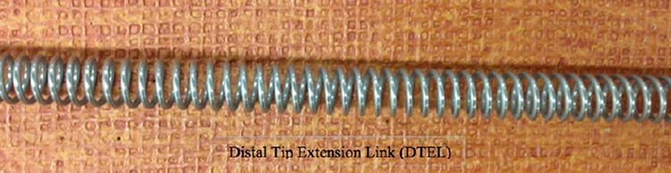 |
Figure 4 The DTEL which is a 60 cm compression spring. |
Telescoping Shaft
The telescoping shaft was created as a part of the distal tip extension mechanism (DTEM). It consists of four solid plastic tubes, as shown in Figure 5. The telescoping shaft is fully extended when the DTEM is not in use and fully compressed when the DTEM is fully extended. When the distal tip extends, the telescoping shaft retracts to allow the insertion tube instruments to move along with the extension of the distal tip. When the distal tip retracts, the telescoping shaft extends to store the extra length of the insertion tube instruments inside of it. The length of the telescoping shaft is 8 cm when fully retracted and 24 cm when fully extended.
 |
Figure 5 The telescoping shaft of the DTEM: illustrates the telescoping shaft when fully extended. |
Experiments
Several experiments were conducted to characterize the performance of the DTEM prototype. The experiments study (1) the effect of implanting the DTEM in the colonoscope on the flexibility of the insertion tube, (2) the ability of the DTEM to elongate the distal tip up to 16 cm and success rate of a full extension when loops exist, (3) the effect of colon configuration on the amount of the forces exerted on the extension knob during the extension of the distal tip, and (4) the bending angle at which the DTEM fails to extend the distal tip of the prototype.
Looping in the Colon
Looping in the colon is one of the complications associated with colonoscopy. It occurs in most of the performed colonoscopies. Sometimes, complications can cause failure by preventing colonoscopists from screening the entire colon. Most of the looping occurs in the sigmoid colon and the transverse colon. Mostly, loops are formed because of the curvatures of the colon. When the distal tip of the colonoscope hits a bend in the colon and the colonoscopist keeps inserting the insertion tube in the colon, loops start forming. Looping occurs in different shapes. The most common shapes of looping are N shape, Alpha shape, and reverse Alpha shape. Many techniques are used to overcome looping such as changing the position of the patient and applying abdominal pressure on the area where loops are forming.20 However, some loops cannot be unformed, unless colonoscopists withdraw the insertion tube out of the patient and reinsert it. Such a practice would prolong the procedure time and make the procedure more uncomfortable for patients. Thus, new methods to enable the distal tip to reach the cecum are needed in order to reduce complications. The DTEM is supposed to be able to elongate the distal tip up to 16 cm even though looping exists, and the insertion tube can no longer be advanced into the colon.
The extension test was performed to investigate the ability of the DTEM to elongate the distal tip up to 16 cm while the colon is in different configurations and loops exist. Also, the extension test was conducted to determine the number of turns that the extension knob needs to make in order to reach full extension for the distal tip. The extension of the distal tip is a combination of rotating the extension knob and compressing the telescoping shaft. Partial extension to the distal tip can be obtained by compressing the telescoping shaft without rotating the extension knob. By moving the instrument control head of the colonoscope forward and holding the extension knob in position, the telescoping shaft is shortened, and the insertion tube instruments push the distal tip forward.
The experiment was set up to simulate the colonoscopy procedure when the colon is in different configurations. A colonoscope training model (CTM) was supposed to be used as a representation of the human colon.21 The CTM has a flexible soft silicon tube. This tube provides a response similar to that of the human colon. The silicon tube can be set up in multiple configurations to simulate different looping shapes.21
The CTM has an anal sphincter opening that can be adjusted via a hand pump. It also has a skin cover used to cover the flexible colon tube. Lubricant gel provided with the CTM was used to facilitate the manipulation of the insertion tube through the silicon tube. However, the idea of using the CTM was abandoned for two reasons, which are direct visualization and adequate space in the CTM. Direct visualization of the extension of the distal tip through the silicon tube is required to follow the movement of the distal tip and collect data. To overcome this obstacle, the lid at the end of the silicon tube was first removed and the tip of the distal tip was placed at the end of the silicon tube, so that the extension of the distal tip can be observed. Adequate space in the CTM is also needed to provide enough space for the distal tip to move 16 cm outside the silicon tube. However, the CTM lacks the needed space because the silicon tube occupies the entire room inside the CTM. Therefore, the body of the CTM was abandoned and only the silicon tube was used in this experiment. The silicon tube was removed from the CTM and placed on a table to provide enough space for the distal tip to extend from the end of the silicon tube. The lid at the end of the silicon tube was removed to maintain direct visualization at the distal dip during the extension. Plastic rings and pins were used to fix the silicon tube to the table in different configurations. Also, a colonoscope stand shown in Figure 6, which is developed by one of Ohio University’s Engineering Department’s mechanical engineering graduate students (Rajesh Ravindra Shanbhag), was used to hold the DTEM prototype during experiments.
 |
Figure 6 The colonoscope holder holds the prototype during performing the extension experiments. |
Additionally, training layouts of the most common configurations, which are N loop, Alpha loop, and reverse Alpha loop, come with the CTM. They were used to simulate the shape of the colon and the loops for the extension test, as shown in Figure 7.
 |
Figure 7 Some of the layouts that come with the CTM. The N shape, Alpha shape, and Reverse Alpha shape are shown because they present the most common looping shapes. |
The extension test was conducted to examine the ability of the DTEM to elongate the distal tip 16 cm while the colon is in different configurations and loops. The three most common loops were simulated using the silicon tube and the training layouts. Five configurations were set up: Straight-line shape, U shape, N shape, Alpha shape, and reverse Alpha shape, as shown in Figure 8. The straight-line shape does not exist in the human colon; however, it was used as a starting point for the experiment. The insertion tube of the prototype was first inserted through the silicon tube until the tip of the distal tip was at the end of the silicon tube. Then, the desired configuration was formed and fixed to the table. Five trials were conducted for each configuration, and the number of turns was recorded at three points. The points are A, B, and C at 5 cm, 10.5 cm, and 16 cm extension, respectively. The extension process was divided into three stages. The first stage was that the telescoping shaft was compressed 5 cm, and the extension knob was rotated until the distal tip reached point A. The extension of the distal tip caused by compressing the telescoping shaft and the number of turns was recorded. The second stage and the third stage were similar to the first stage with one exception. The exception is that the telescoping shaft was compressed 5.5 cm in each of the two stages instead of compressing 5 cm. Also, the extension knob was rotated until the distal tip reached point B and point C, in the second stage and the third stage, respectively. The extension caused by compressing the telescoping shaft and the number of turns was recorded at each point. To compress the telescoping shaft, the extension knob was held in position while the instrument control head of the prototype was pushed toward the extension knob.
 |
Figure 8 Illustration of the five configurations used in the extension test. |
Torque Test
To study the effect of the colon configuration on the torque applied on the extension knob to displace the distal tip 16 cm the torque test was performed. Also, the average torque force and the maximum torque exerted on the extension knob during the extension of the distal tip for each configuration were calculated. During the extension of the distal tip, torque is applied on the extension knob to rotate it, causing the compression spring to rotate and move the distal tip. The torque is applied by hand on the extension knob. Four colon configurations were formed and studied for the torque test.
The setup of the torque test is similar to the setup of the extension test. The silicon tube was used as well as the table, plastic rings, pins, and training layouts. Four colon configurations were set up, which are U shape, Alpha shape, reverse Alpha shape, and N shape, as shown in Figure 8. Furthermore, the dual-range force sensor and the Vernier LapPro device described previously were utilized in this experiment. The force sensor was connected to the extension knob, as shown in Figure 9.
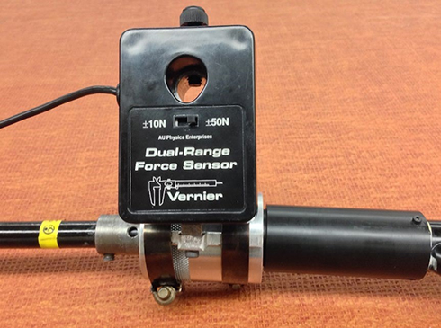 |
Figure 9 The force sensor attached to the extension knob of the DTEM. |
The torque test aimed to observe the effect of the colon configuration on the amount of the torque applied on the extension knob to extend the distal tip. The maximum torque applied on the extension knob during the extension process of the distal tip was recorded. Since the extension process of the distal tip was divided into three stages, average torque for each stage was calculated. For the torque test, U shape, Alpha shape, reverse Alpha shape, and N shape were set up using the silicon tube, plastic rings, pins and flat table. The force sensor connected to the Vernier LapPro device was attached to the extension knob to record the force applied on it by hand. During the extension of the distal tip, the force sensor was pushed by hand to rotate the extension knob. The data was collected at the end of each stage of the extension process of the distal tip. The obtained results were displayed and saved on the computer, which is connected to the Vernier LapPro device.
Bending Test
The insertion tube of colonoscope should be able to bend in various degrees to negotiate the bends of the human colon. The bending test is performed to determine the bending limits of the insertion tube of the prototype. Furthermore, the bending angle at which the DTEM fails to extend the distal tip and the effect of bending on the number of turns needed to achieve full extension is studied.
The bending angle test was designed to determine the bending angle limits, and to study the effect of bending on the ability of the DTEM to elongate the distal tip in terms of the number of turns of the extension knob, as well as to determine the bending angle at which the DTEM fails to extend the distal tip. The experiment covered only the area where the compression spring and the spring of the DTEL overlapped. The bending section of the insertion tube, also referred to as the distal tip, usually bends in different angles in order to maneuver through the bends of the human colon. Furthermore, one of the goals of the DTEM is to enable the distal tip to reach the cecum. Thus, the distal tip should at least be within the ascending colon before the DTEM is used, since the average length of the ascending colon is about 16 cm. A portion of the insertion tube, which is the part right before the beginning of the distal tip, would curve in the hepatic flexure. This curve was simulated in this test by bending the portion of the insertion tube in different angle degrees.
The setup of the bending angle test shown in Figure 10 required a flat table to lay the insertion tube on, a protractor to measure the bending angles, and a flexible bending tube. Also, metal clamps and pins were used to fix the insertion tube of the prototype to the table. First of all, the protractor was laid down on the table, and then lines were drawn on the table presenting the angles’ degrees that were used in the test. The angles started from 0 to 180 degrees. The increment of the bending angle was 30 degrees from 0 to 150, and then the increment was reduced to 10 for the remaining bending angles. Since the DTEM was expected to fail in the interval, 150 and 180 bending angles, the increment of the bending angle was reduced from 30 to 10 in this interval to enhance the accuracy of the results. The flexible bending tube was made of two transparent solid tubes and a flexible corrugated tube, as shown in Figure 11. The corrugated tube was attached to the transparent tubes. The corrugated tube was used to bend the insertion tube at different angles. The flexible bending tube performs two jobs, which are forcing the insertion tube to bend and holding the insertion tube in position during the experiment.
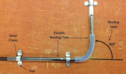 |
Figure 10 Setup of the bending angle test with illustration of the main components. The bending angle being tested in this figure is 90°. |
 |
Figure 11 The flexible bending tube consists of two transparent tubes and one corrugated tube. The device is used to bend the insertion tube in different angles. |
The bending angle test was performed to investigate the ability of the DTEM to extend the distal tip when the insertion tube is bent into different angles. The angles chosen for this experiment are 0, 30, 60, 90, 120, 150, 160, 170, and 180 degrees. Marks were first made on the flat table to illustrate the bending angle sizes. Then, the flexible tube was inserted over the insertion tube, placing the portion of the insertion tube that was bent in the corrugated tube. The insertion tube along with the flexible tube was fixed to the table using the metal clamps and pins. Once the insertion tube was placed in position for the experiment, the telescoping shaft was compressed and the extension knob was rotated until full extension was reached. Three trials were performed at each bending angle to reduce experimental errors. The total number of turns needed to achieve full extension was recorded at the end of each trial. When the DTEM successfully extended the distal tip 16 cm, the insertion tube was bent to the next bending angle until the DTEM failed to extend the distal tip. The bending angle at which the DTEM failed was marked as failed, and the experiment was ended.
Results and Discussions
Extension Test Data
The extension test is conducted to demonstrate the ability of the DTEM to displace the distal tip of the insertion tube 16 cm on a pass/fail basis, and determine the number of turns that the extension knob needs to make in order to extend the distal tip 16 cm. Also, the test aims to study the effect of the colon configuration on the number of turns and on the ability of the DTEM to perform to its full extension. The obtained results from running the extension test are presented in this section. The 16 cm extension of the distal tip is a combination of three stages referred to as first segment (5 cm), second segment (5.5 cm), and third segment (5.5 cm).
Figure 12 illustrates the displacements of the distal tip due to shortening the length of the telescoping shaft gradually in three stages. The first stage is pushing the first tube inside the telescoping shaft, the second stage is pushing the second tube in the telescoping shaft, and the third stage is pushing the third tube in the telescoping shaft. The results presented below show that the distal tip moves differently in each stage and in each configuration.
 |
Figure 12 The displacements of the distal tip caused by pushing the three tubes of the telescoping shaft gradually in the telescoping shaft. |
Figure 13 demonstrates the numbers of turns of the extension knob for each of the three stages associated with each configuration. Also, it illustrates that the number of turns in each stage varies in each configuration.
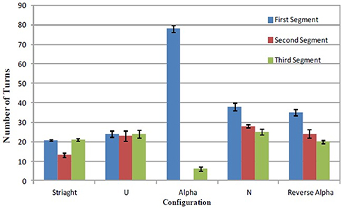 |
Figure 13 The numbers of turns of the three stages in each configuration. |
Figure 14 shows the displacement percentage caused by compressing the telescoping shaft 16 cm and rotating the extension knob. When the telescoping shaft is compressed 16 cm, the distal tip moves forward less than 16 cm. Therefore, the extension knob is next rotated to force the distal tip to reach the full 16 cm extension. The response of the distal tip to compressing the telescoping shaft varies in accordance with the shape of the configuration, and that influences the number of turns associated with each configuration, as shown in Figure 14.
 |
Figure 14 The displacement percentage caused by both compressing the telescoping shaft and rotating the extension knob. |
Table 1 presents the success rate of the DTEM to extend the distal tip 16 cm. The overall number of trials performed in the extension test is 25, five for each colon configuration. Based on the presented results in Table 1, the overall success rate is 100%, and the DTEM is significantly able to extend the distal tip of the colonoscope to its full extension (16 cm) in all the setup configurations.
 |
Table 1 The Success Rates of the DTEM to Extend the Distal Tip 16cm |
The shapes of the configurations are found to influence the ability of the DTEM to move the distal tip to its full extension (16 cm) in terms of the displacement caused by pushing the telescoping shaft and the number of turns of the extension knob. The displacement of the distal tip is affected by the friction between the inner surface of the insertion tube and the springs of the DTEM, as well as the number and the degree of the bends along the configurations. The effect of friction is observed from the variation of the displacement among the three stages of extension for each configuration. The displacement from the first stage is less than that from the second stage. Also, the displacement from the second stage is less than the displacement from the third stage. This phenomenon can be explained by the fact that the contact surface area between the inner surface of the insertion tube and the springs of the DTEM reduces as the extension process moves from the first stage to the second stage and then to the third stage. At the beginning of first stage, the entire length of the DTEL’s spring is inside the insertion tube, and a portion, 5 cm, from the length of the spring is out of the insertion tube at the end of first stage. As a result, the amount of contact area lessens during the second stage. Furthermore, at the end of the second stage, 10.5 cm from the DTEL spring’s length is out of the insertion tube, which means that the contact area decreases during the third stage of the extension process.
The number and size of the curves along the insertion tube influence the extension process of the distal tip. More complicated configurations require a larger number of turns to overcome the resistance along the curves. Therefore, the N configuration is found to be associated with the maximum number of turns among the studied configurations because it has the highest number of bends. On the other hand, the straight-line configuration is correlated with the minimum number of turns, since it has no bends. Furthermore, the Alpha shape and the reverse Alpha shape have approximately similar numbers of turns because they have the same number, but slightly different sizes, of bends.
Some uncertainties in experimental results can be caused by the springs’ coils of the DTEM being wedged in between the coils of the metal flex tube of the insertion tube. The metal flex tube is the internal surface of the insertion tube, as shown in Figure 15. During the extension process of the distal tip, the compression spring is rotated and the DTEL spring is moved through the insertion tube. When one of the DTEL spring’s coils or more is stuck between the coils of the metal flex tube, the extension of the distal tip is affected. Thus, a larger number of turns will be needed in order to generate a greater pushing force to move the DTEL spring out of the area where the spring is stuck.
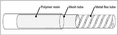 |
Figure 15 The insertion tube of the colonoscope consists of three layers: Polymer resin, mesh tube, and metal flex tube.22 |
Torque Test Data
The obtained results from conducting the torque test are shown in Figure 16. The presented torques are calculated from multiplying the forces recorded by the force sensor by the radius of the Extension knob which is 2.3 cm. The results show that the average torque applied on the extension knob by hand to rotate the compression spring and extend the distal tip decreases as the extension process moves from the first stage to the third stage. Also, it is observed from Figure 16 that more complicated configurations require higher torque to rotate the extension knob. Furthermore, the N shape is associated with the maximum average torque, and the U shape is correlated with the minimum average torque. Additionally, Table 2 demonstrates the maximum torque exerted on the extension knob during the extension of the distal tip for each configuration.
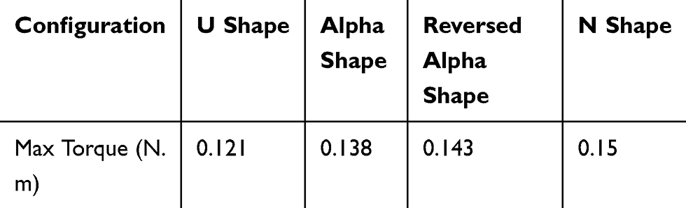 |
Table 2 Maximum Torque Applied During the Extension of the Distal Tip in Each Configuration |
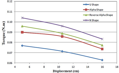 |
Figure 16 Torque needed to rotate the extension knob and displace the distal tip in each stage of the extension process in all studied configurations. |
The results shown in Figure 17 demonstrate that the shape of the configurations influences the amount of torque needed to rotate the extension knob. More complex shapes need greater torque to rotate the extension knob because they are associated with higher friction. Each configuration has a different number and size of curves along the insertion tube. Therefore, the four configurations require different torques to overcome friction in order to rotate the compression spring and move the distal tip. The N shape is associated with the maximum torque since it has more curves than the other configurations. Also, the U shape requires the minimum torque to rotate the extension knob because it has the least number of curves. Friction between the inner surface of the insertion tube and the surface of the compression spring and the DTEL spring affects the value of torque needed to rotate the extension knob.
 |
Figure 17 The average torque applied to rotate the extension knob to reach full extension for the distal tip in the configurations. |
The results also show that the torque needed to rotate the extension knob decreases as the extension process moves from the first stage to the third stage for all the configurations. This is explained by the fact that when the extension process advances from the first stage to the second stage, friction decreases because the contact surface area between the springs and the inner surface of the insertion tube becomes less. Also, the friction decreases even more when the extension process moves from the second stage to the third stage because the contact surface area is the least during the third stage.
During the extension of the distal tip in the four configurations, the force sensor recorded some unusually high torque values. These high torques were caused by the DTEL spring’s coils being stuck between the coils of the metal flex tube shown in Figure 14. When one or more spring’s coils are stuck between the coils of the metal flex tube, higher torque is required to move the spring of the DTEL.
The obtained results from the torque test coincide with the results from the extension test. They both prove that as the extension process moves from the first stage to the third stage, the friction becomes less. Also, some uncertainties in the results are caused by the DTEL spring’s coils being stuck between the coils of the metal flex tube. Furthermore, more complicated configurations required a higher number of turns and torques to move the distal tip since they have a higher number of curves, which increases friction.
Bending Test Data
The bending test aims to determine the bending angles’ ranges in which the DTEM can generate full extension to the distal tip. Since the test requires the usage of DTEM, the number of turns needed for extension during the test is recorded as well.
Bending Angle Data
The bending angle test is performed to determine the limits of the bending angles at which the DTEM is able to fully extend the distal tip. The illustrated results in Figure 18 show that the number of turns increases as the value of the bending angle increases. Also, the DTEM is able to successfully move the distal tip (16 cm) while the insertion tube is bent to the bending angles shown in Figure 18. The maximum bending angle at which the DTEM can extend the distal tip is 160°.
 |
Figure 18 Bending Angles and number of turns obtained from testing the insertion. |
The extension process of the distal tip is influenced by the size of the bending angle since a smaller bending angle is correlated with a higher friction force. The friction is produced from bending the insertion tube, which causes the DTEM springs to push back on the internal surface of the insertion tube to resist bending and to restore their original shape. The smaller that the bending angle is, the more coherent the attachment between the inner surface of the insertion tube and the springs of the DTEM is, as well as the higher the friction is. Thus, as the size of the bending angle increases, the needed number of turns to move the distal tip increases in order to generate a higher pushing force on the DTEL spring to exceed the increased friction force. The DTEM fails to extend the distal tip 16 cm when the bending angle is higher than 160° because the pushing force, generated from pushing the telescoping shaft and rotating the extension knob, exerted on the DTEL spring does not overcome the existing friction force.
Conclusion
Development of DTEM Prototype
The final DTEM prototype consisted of four main parts, which were a compression spring, a distal tip extension link (DTEL), an extension knob, and a telescoping shaft. The compression spring was connected to the extension knob at one end and overlapped with the DTEL spring at the other end. The compression spring rotated with the rotation of the extension knob, generating pushing and pulling forces on the DTEL spring depending on the direction of rotation. The DTEL was connected to the distal tip of the insertion tube and was overlapped with the compression spring. The DTEL moves because of the force applied on it by the compression spring, and this movement displaces the distal tip. The extension knob was used to rotate the compression spring to generate the push and pull forces, and it was also used to separate the rotation of the compression spring from the rest of the colonoscope. The telescoping shaft provided the 16 cm additional length of the accessories during the extension of the distal tip, and it also displaced the distal tip when it is compressed.
Ability of the DTEM to Extend the Distal Tip
The results presented in Extension Test Data demonstrated that the DTEM is able to extend the distal tip 16 cm while the colon is in different configurations. The DTEM was able to successfully displace the distal tip in all of the 25 performed trials. Only 5 trials were conducted for each test because the obtained data showed similar results; thus, it was not needed to conduct more trials. Therefore, the DTEM can help increase the colonoscopy completeness rate by increasing the length of the insertion tube, since incomplete colonoscopy can be caused by a long colon and/or the lack of length of the insertion tube.23 Additionally, the obtained results from the extension test proved that the circumference structure of the insertion tube is nonhomogenous. Furthermore, the maximum number of turns, 91 turns, needed to extend the distal tip was associated with the N configuration. Also, the minimum number of turns, 55 turns, was correlated with the straight-line shape. The variation in the number of turns needed to displace the distal tip 16 cm among the five studied configurations proves that the shape of the configuration influences the number of turns. Complicated configurations necessitate a higher number of turns.
Effect of Colon Configuration on the Applied Torque
The results presented in Torque Test Data proved that the configuration of the colon influences the value of torque applied on the extension knob in order to extend the distal tip. Complicated configurations require higher torque to exceed friction between the internal surface of the insertion tube and the surface of the springs of the DTEM. Also, the torque required to rotate the extension knob decreases as the extension of the distal tip increases since friction decreases with the extension of the distal tip.
Effect of Bending on the Performance of the DTEM
The bending angle test was conducted to determine the maximum bending angle at which the DTEM is able to displace the distal tip 16 cm. The obtained results showed that the minimum bending angle is 160°. Therefore, it is concluded that the DTEM is able to extend the distal tip as long as the bending angle is less than or equal to 160°.
Acknowledgment
This research was not supported by any funding agencies, commercial, or not-for-profit sectors.
Disclosure
The authors report no conflicts of interest in this work.
References
1. Levin B, Lieberman DA, McFarland B, et al. Screening and surveillance for the early detection of colorectal cancer and adenomatous polyps, 2008: a joint guideline from the American Cancer Society, the US Multi‐society Task Force on Colorectal Cancer, and the American College of Radiology*†. CA Cancer J Clin. 2008;58(3):130–160. doi:10.3322/CA.2007.0018
2. Cotton PB, Williams CB. Practical Gastrointestinal Endoscopy. Oxford, UK: Blackwell Scientific Publications; 1990:214–215. Chap 9.
3. Ng WS, Phee SJ, Seow C, Davies BL. Development of a robotic colonoscope. Digest Endoscopy. 2000;12(2):131–135. doi:10.1046/j.1443-1661.2000.00039.x
4. Rex DK, Bond JH, Winawer S, et al. Quality in the technical performance of colonoscopy and the continuous quality improvement process for colonoscopy: recommendations of the US Multi-society Task Force on Colorectal Cancer. Am J Gastroenterol. 2002;97(6):1296–1308. doi:10.1111/j.1572-0241.2002.05812.x
5. Chen PJ, Shih YL, Chu HC, Chang WK, Hsieh TY, Chao YC. A prospective trial of variable stiffness colonoscopes with different tip diameters in unsedated patients. Am J Gastroenterol. 2008;103(6):1365–1371. doi:10.1111/j.1572-0241.2008.01812.x
6. Arber N, Grinshpon R, Pfeffer J, Maor L, Bar-Meir S, Rex D. Proof-of concept study of the Aer-O-scope™ omnidirectional colonoscopic viewing system in ex vivo and in vivo porcine models. Endoscopy. 2007;39(05):412–417. doi:10.1055/s-2007-966452
7. Eickhoff A, Jakobs R, Kamal A, Mermash S, Riemann JF, van Dam J. In vitro evaluation of forces exerted by a new computer-assisted colonoscope (the NeoGuide Endoscopy System). Endoscopy. 2006;38(12):1224–1229. doi:10.1055/s-2006-945014
8. Raju GS, Rex DK, Kozarek RA, Ahmed I, Brining D, Pasricha PJ. A novel shape-locking guide for prevention of sigmoid looping during colonoscopy. Gastrointest Endosc. 2004;59(3):416–419. doi:10.1016/S0016-5107(03)02709-3
9. Cataldo PA. Colonoscopy without sedation. Dis Colon Rectum. 1996;39(3):257–261. doi:10.1007/BF02049463
10. Mitchell RMS, McCallion K, Gardiner KR, Watson RGP, Collins JSA. Successful colonoscopy; completion rates and reasons for incompletion. Ulster Med J. 2002;71(1):34–37.
11. Saunders BP, Macrae F, Williams CB. What makes colonoscopy difficult? Gut. 1993;34(suppl 1):T179.
12. Park HJ, Hong JH, Kim HS, et al. Predictive factors affecting cecal intubation failure in colonoscopy trainees. BMC Med Educ. 2013;13(1):5. doi:10.1186/1472-6920-13-5
13. Koido S, Ohkusa T, Nakae K, et al. Factors associated with incomplete colonoscopy at a Japanese academic hospital. World J Gastroenterol. 2014;20(22):6961. doi:10.3748/wjg.v20.i22.6961
14. Shah HA, Paszat LF, Saskin R, Stukel TA, Rabeneck L. Factors associated with incomplete colonoscopy: a population-based study. Gastroenterology. 2007;132(7):2297–2303. doi:10.1053/j.gastro.2007.03.032
15. Bowles CJA, Leicester R, Romaya C, Swarbrick E, Williams CB, Epstein O. A prospective study of colonoscopy practice in the UK today: are we adequately prepared for national colorectal cancer screening tomorrow? Gut. 2004;53(2):277–283. doi:10.1136/gut.2003.016436
16. Cotton PB, Connor P, McGee D, et al. Colonoscopy: practice variation among 69 hospital-based endoscopists. Gastrointest Endosc. 2003;57(3):352–357. doi:10.1067/mge.2003.121
17. Loffeld RJLF, van der Putten ABMM. The completion rate of colonoscopy in normal daily practice: factors associated with failure. Digestion. 2009;80(4):267270. doi:10.1159/000236030
18. Sadahiro S, Ohmura T, Yamada Y, Saito T, Taki Y. Analysis of length and surface area of each segment of the large intestine according to age, sex and physique. Surg Radiol Anat. 1992;14(3):251–257. doi:10.1007/BF01794949
19. Loeve AJ, van de Ven OS, Vogel JG, Breedveld P, Dankelman J. Vacuum packed particles as flexible endoscope guides with controllable rigidity. Granular Matter. 2010;12(6):543–554. doi:10.1007/s10035-010-0193-8
20. Messmann H. Atlas of Colonoscopy: Techniques, Diagnosis, Interventional Procedures. New York: Thieme; 2006:
21. Colonoscopy Training Model, kyoto Kagaku, [online]. Available from: http://www.kyotokagaku.com/products/detail01/pdf/m40_catalog.pdf.
22. Saito Y, Kimura H. Responsive insertion technology. Digest Endoscopy. 2011;23(s1):164–167. doi:10.1111/j.1443-1661.2011.01136.x
23. Church JM. Complete colonoscopy: how often? And if not, why not? Am J Gastroenterol. 1994;89(4):556–560.
 © 2020 The Author(s). This work is published and licensed by Dove Medical Press Limited. The
full terms of this license are available at https://www.dovepress.com/terms
and incorporate the Creative Commons Attribution
- Non Commercial (unported, 3.0) License.
By accessing the work you hereby accept the Terms. Non-commercial uses of the work are permitted
without any further permission from Dove Medical Press Limited, provided the work is properly
attributed. For permission for commercial use of this work, please see paragraphs 4.2 and 5 of our Terms.
© 2020 The Author(s). This work is published and licensed by Dove Medical Press Limited. The
full terms of this license are available at https://www.dovepress.com/terms
and incorporate the Creative Commons Attribution
- Non Commercial (unported, 3.0) License.
By accessing the work you hereby accept the Terms. Non-commercial uses of the work are permitted
without any further permission from Dove Medical Press Limited, provided the work is properly
attributed. For permission for commercial use of this work, please see paragraphs 4.2 and 5 of our Terms.