Back to Journals » International Journal of Nanomedicine » Volume 10 » Issue 1
Effects of graphene plates’ adoption on the microstructure, mechanical properties, and in vivo biocompatibility of calcium silicate coating
Authors Xie Y, Li H, Ding C, Zheng X, Li K ![]()
Received 21 November 2014
Accepted for publication 16 February 2015
Published 8 June 2015 Volume 2015:10(1) Pages 3855—3863
DOI https://doi.org/10.2147/IJN.S77919
Checked for plagiarism Yes
Review by Single anonymous peer review
Peer reviewer comments 3
Editor who approved publication: Professor Lei Yang
Youtao Xie, Hongqin Li, Chuanxian Ding, Xuebin Zheng, Kai Li
Shanghai Institute of Ceramics, Key Laboratory of Inorganic Coating Materials, Chinese Academy of Sciences, Shanghai, People’s Republic of China
Abstract: Calcium silicate (CS) ceramic is a good coating candidate for biomedical implants to improve biocompatibility and accelerate early osseo-integration. However, the poor fracture toughness and wear resistance of this ceramic material restricts the long-term performance of implants. In this study, graphene plates (GPs) were used as reinforcement to improve the mechanical properties of CS coating. Composite coating containing 1.5 weight % GPs was prepared by vacuum plasma spraying technology. The good survival of the GPs in the composite coating was demonstrated by Raman analysis, although the defects of the GPs were increased after plasma spraying. Effects of the GPs’ adoption on the microstructure of the coating were studied by scanning electron microscopy and transmission electron microscopy. Results showed that the GPs were homogenously distributed in the CS grains interface or enwrapped on the particles, and exhibited good wetting behavior with the CS matrix. The wear properties of the composite coating were obviously enhanced by the reinforcement of GPs. The reinforcement mechanism was attributed to the enhanced micro-hardness and interfacial bonding of the particles in the coating. In vivo experiments demonstrated that the composite coating possessed similarly good biocompatibility compared to pure CS coating. The bone-implant contact ratio reached 84.3%±7.4% for GPs/CS coating and 79.6%±9.4% for CS coating after 3 months’ implantation.
Keywords: graphene plates, coating, microstructure, wear resistance, biocompatibility
Introduction
For an ideal coating material in orthopedic applications, comprehensive properties including good biocompatibility, high bonding strength with substrate, and excellent wear resistance are needed. Resulting from the insufficient initial fixation and movement of the limb, micro-vibration of total hip implant is ineluctable.1,2 Rough surfaces fabricated by plasma spraying has been widely used in clinical practice as an attempt to improve the mechanical compatibility and early fixation of the implants.3,4 Hydroxyapatite (HA) is the widely used coating material because of its similar inorganic components as the natural bone and excellent biocompatibility.5,6 However, the relatively rapid degradation of HA coating in biological environment due to the low crystallinity, poor bonding strength with metal substrates, and poor wear resistance affects its long-term performance.7,8
Calcium silicate (CS) coatings show not only good biocompatibility but also excellent bonding strength with Ti alloy substrate. They are suitable coating material candidates for load-bearing implants.9,10 Silicon, one of the main components of CS, is an essential trace element in animal nutrition and has very important functions in the early stage of bone and ligament tissue formation.11 Hydrated silica gel can enhance the proliferation of osteoblasts and activates the production of transforming growth factors.12,13 Ca is also an important composition element of bone tissues. Ca ions’ implantation in Ti not only improved the spreading and attachment of MG-63 cells,14 but also enhanced the growth of bone tissue in vivo.15,16 However, the intrinsic brittleness and mechanical unreliability of the CS ceramic restricts the long-term performance of the implants. Particulate debris produced by the micro-movements is harmful to the stable fixation of implants.
Graphene is the basic structural unit of C allotropes, such as graphite, C nanotubes and fullerenes. It is a single layer of C atoms packed in a honeycomb crystal lattice. Because of its high specific surface area, aspect ratio, tensile strength, thermal and electrical conductivity and flexibility, graphene is a preferred nanofiller compared to other conventional C materials, such as nanotube, nanofiber, expandable graphite, etc.17–19 The intrinsic strength and Young’s modulus of graphene is similar or slightly higher than the defect-free nanotube.20 Its thermal conductivity is the highest among the other known materials up until now.2 In addition to the widely used application as nanofillers in polymers, graphene is also a good reinforcement for ceramic materials.21,22 Si3N4 ceramic with 1.5 volume % graphene addition obtained by spark plasma sintering showed significantly enhanced fracture toughness up to 6.6 MPa·m1/2 (nearly 235% higher than pure Si3N4).23 The flexural strength and fracture toughness of the graphene doped alumina ceramic were enhanced 30.75% and 27.20%, respectively. HA ceramic containing 1.0 weight (wt) % graphene exhibited ~80% improvement in fracture toughness.24 The main toughening mechanisms which originated from the presence of the graphene are contributed to grain bridging, crack bridging, and crack deflection.
Graphene shows not only excellent mechanical properties but also good biocompatibility. It was widely used in biomedical applications for improving mechanical/electrical properties of biomaterials and accelerating the early cell responses, etc. Application fields include biomedical engineering, regenerative medicine and biotechnology.25,26 The behaviors of human osteoblasts and human marrow stem cells (hMSCs) were significantly enhanced on the graphene surface compared to those on the SiO2 substrates.27 A significant improvement of osteoblasts’ adhesion and apatite mineralization was obtained by graphene adoption in HA ceramic.24 A series of titania/graphene nano-composites were synthesized using in situ sol–gel method and were used for repairing bone defects.28 An enhanced human cell attachment was obtained. In our previous work, various ratios of graphene were used to reinforce CS coating.29 Preliminary in vitro cytocompatibility evaluation was performed using hMSCs. Results showed that the composite coating possessed similar cytocompatibility compared to the pure CS coating.
In the present work, 1.5 wt % graphene plates (GPs) were added to CS powder. The composite powder was applied to fabricate a coating on Ti alloy substrates using vacuum plasma spraying technology. Effects of the GPs’ adoption on the microstructure and wear properties of the CS coating were studied. In vivo biocompatibility of the composite coating was evaluated using a New Zealand White rabbit model.
Experimental processes
Preparation and characterization of the composite coatings
CS powders were prepared by sol–gel process using reagent-grade Ca nitrate tetrahydrate (Ca(NO3)2·4H2O) and tetraethoxysilane (Si(OC2H5)4, TEOS, 98.0%) with an initial CaO/SiO2 molar ratio of 1.0. In brief, Ca nitrate tetrahydrate and TEOS mixture was hydrolyzed via the sequential addition of 2 M HNO3 and absolute ethanol. After mixing by vigorous stirring for 5 hours, the obtained suspension was aged overnight, and dried at 105°C for 48 hours. The CS powder was obtained by calcination of the dried gel at 800°C for 3 hours. The resultant powders were ground and sifted through a 150 mesh, and used for preparation of composite powders.
Mechanical ball milling technique was performed for homogeneous dispersion of 1.5 wt % GPs (thickness =5~20 nm, XF Nano, Nanjing, People’s Republic of China) in CS powder. In detail, GPs were first dispersed in N,N-Dimethylformamide (DMF) and sonicated for 30 minutes. And then, CS powder was added and sonicated for another 20 minutes. The composite suspension was then ball milled at 200 rpm in a planetary ball mill for 6 hours to produce a powder mixture. The GP/CS composite coating with Ti-6Al-4V as substrates was deposited by vacuum plasma spraying system (Sulzer Metco, Wohlen, Switzerland).
The microstructure of the powders and coatings was observed using scanning electron microscopy ([SEM] JSM-6700F; JEOL, Tokyo, Japan). The phase composition was examined by X-ray diffraction ([XRD] RAX-10; Rigaku, Tokyo, Japan), using Cu Kα (λ=0.154056 nm) radiation at 40 kV and 100 mA. The GPs in the composite coating was analyzed by DXR Micro-Raman spectroscopy (Thermo Fisher Scientific, Waltham, MA, USA) and transmission electron microscopy (TEM) (JSM, 2100F, JEOL).
Hardness and tribological behaviors of the coating
Effects of the GPs’ addition on the hardness of the coating were measured by a micro-hardness tester (Model HX-1000, Shanghai Aolong Xingdi Testing Instrument Co. Ltd., Shanghai, People’s Republic of China). A load of 1.96 N (200 g) for 15 seconds (s) was applied for the indentation. The average values of 30 test data are reported.
Tribological properties of the coating were measured on a micro-tribometer tester (UMT-3; Bruker Corporation, Capbell, CA, USA) with a ball-on-disc model. The wear load was assigned at 10 N after comprehensive consideration of the human body mass and test condition. A stainless steel ball was used as the counter surface. The wear debris and track were observed by SEM.
In vivo biocompatibility experiments
New Zealand White rabbits (male, 3 months old, 2.5–3.0 kg) were used for in vivo biocompatibility evaluation and the femur condyle defect model was employed. The use of animals and the experimental protocols were approved by the Institutional Animal Welfare Committee of Shanghai Jiao Tong University. Rabbits were anesthetized by injecting 3% Nembutal (30 mg/kg) via the ear vein and a longitudinal incision was made by scalpel in the rabbit femur under rigorous aseptic conditions. Defects in each femoral condyle were made by a Ø2 mm drill toward the medial epicondyle orientated perpendicular to the longitudinal and sagittal axes.30 Ten implants (2×10 mm) coated with GP/CS coating (with similar number of CS coated samples for comparison) were sterilized and implanted. To avoid wound infection, each animal was given an intramuscular injection of 400,000 U penicillin per day for 3 days after operation.
At 1 and 3 months post-implantation, the rabbits were first anesthetized with 3% Nembutal, and then sacrificed by injecting air into the heart. Body tissue around the implants was obtained. The samples were fixed in 4% paraformaldehyde buffer in phosphate-buffered saline for 10 days and then dehydrated using an ascending series of alcohol (75%, 95%, and 100%, increasing every 3 days). The dehydrated sample was embedded in Technovit 7200VLC (Exakt, Norderstedt, Hamburg, Germany) for 10 days, and then polymerized for 2 days by the EXAKT 520 Light Polymerization System (Exakt). Sectional samples (50 mm) were obtained perpendicular to the implants and stained by picric acid fuchsin staining for histological observation. A semi-automatic image analysis system (BIOQUANT) was applied for measuring the amount of bone-implant contact (BIC). BIC levels were defined as the fraction of direct bone apposition at the surface of the implant. The values were the mean of five samples.
Results and discussion
Characteristics of the coating
The SEM morphologies of the feedstock and sprayed composite coating are shown in Figure 1. It can be seen in Figure 1A that the feedstock particles were aggregated by many small CS particles and GPs. The GPs were well dispersed and mixed homogenously with the CS powder as shown in Figure 1B. The small CS particles were adhered together by the GPs. SEM morphology of the GPs/CS coating show a typical hierarchical structure with a lot of nano-scaled particles adhering on the relatively large particle surface (Figure 1C). This kind of hierarchical hybrid structure was reported to be beneficial to the biological performance of the coating.31,32
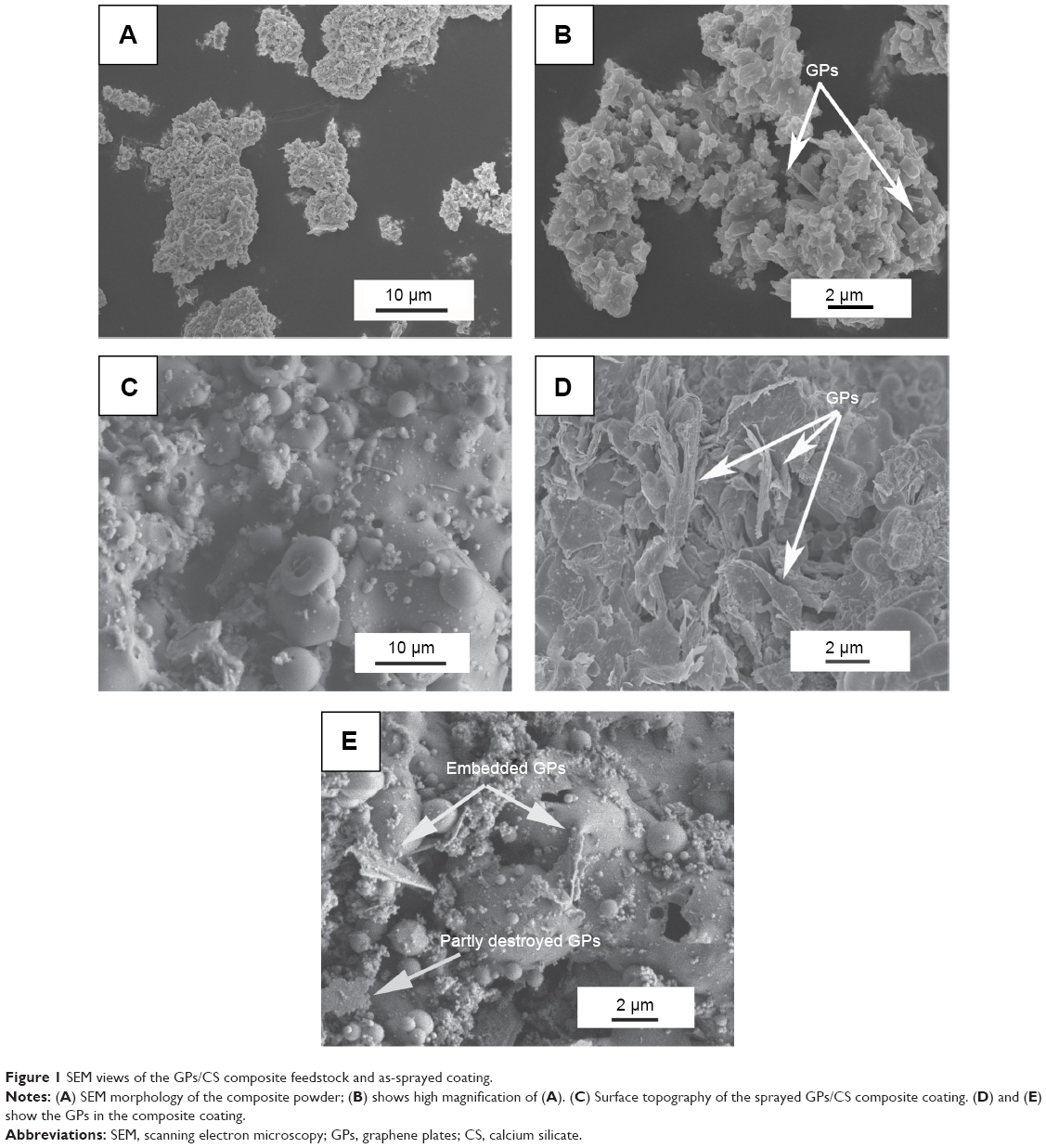 | Figure 1 SEM views of the GPs/CS composite feedstock and as-sprayed coating. |
The GPs should good survival after the plasma spraying process and exhibited good wetting behaviors with the CS matrix as demonstrated in Figure 1D and E. Most of them were homogenously distributed in the CS grain interface or semi-enwrapped in the CS particles. However, no C peaks were found on the XRD spectra of the as-sprayed GPs/CS coating (Figure 2) or the feedstock. It may be explained by the relatively low doping amount of the GPs and low strength of the C peaks. The XRD patterns presented in Figure 2 indicate that only CS peaks (wollastonite-2M, JCPDS card: no 43-1460) could be detected. In addition, an obvious glass bulge coexisted with the sharp peaks of wollastonite for the coatings. The peak strength of the GPs/CS coating was the lowest among the three spectra. It may be contributed to the good thermal conductivity of the GPs and rapid heating and cooling of the composite coating in the plasma spraying process.
 | Figure 2 XRD patterns of the GPs/CS composite powder, CS and GPs/CS coatings. |
To further detect the GPs’ existence in the coating, Raman analysis was performed in this study. The G and D peaks in the Raman spectra are the straightforward demonstration of the existence and “molecular” picture of C materials.33 The peak at 1,580 cm−1 (G-band) is due to the bond stretching of all pairs of sp2 atoms in both rings and chains, while the D peak (at 1,350 cm−1) represents the breathing modes of sp2 atoms in rings.34,35 From the Raman spectra shown in Figure 3, D and G peaks confirmed the retention of C materials in the plasma sprayed coating. The D peak strength indicates the number of defects in the C materials.33 Increased D peak strength means increased defect density and edges. In Figure 3, the D peak strength increased significantly in the as-sprayed coating, which indicated that the defects increased after the plasma spraying process. It may be explained by the high temperature of plasma spraying or mechanical exfoliation in the ball milling process. Obviously decreased ID/IG values were observed for the GPs after plasma spraying. Reduction of ID/IG ratio meant the graphitization of GPs in the composite coating. Similar purification and graphitization for C nanotubes were also reported.36–40 Due to the high temperature process of plasma spraying, the C atoms diffuse to decrease the surface area of GPs and to lower the surface free energy.
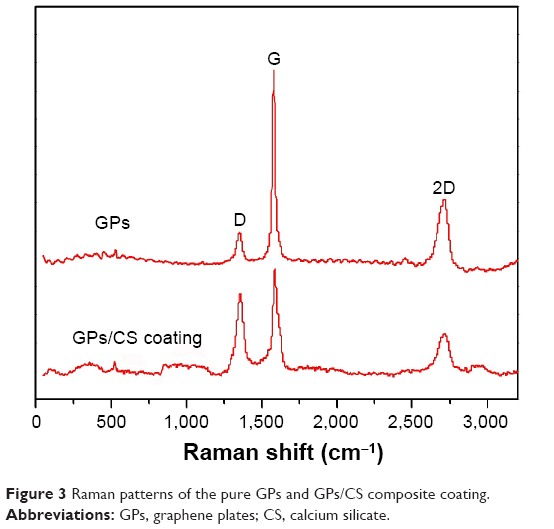 | Figure 3 Raman patterns of the pure GPs and GPs/CS composite coating. |
Micro-hardness and tribological behavior of the coating
Good wear resistance is not only beneficial to the mechanical fixation of load bearing implants, but also the requirement for long-term biological performance. Wear debris produced from the implants may lead to harmful results. The foreign elements from the wear debris affect the viability of osteoblasts at the implant surface,41 release bone-resorbing mediators stimulating excess osteoclastic differentiation,42–46 and finally result in osteolysis and implant loosening. In this study, the debris generated in the wear process of GPs/CS and CS coatings was measured by a pin-on-disc model with a load of 10 N and sliding distance of 500 m. A stainless steel ball was used as the sliding counter. The GPs/CS coating exhibited an obvious enhancement of wear resistance by the adoption of GPs. The mass loss of the GPs/CS coating was only 1.3±0.2 mg, while that of the pure CS coating reached up to 28.6±0.5mg.
The wear properties of materials are closely related to the hardness. The micro-hardness of the composite coating was measured in this study. The measured values for CS and GPs/CS coatings are 2.5±0.3 GPa and 2.8±0.4 GPa, respectively. With the high micro-hardness of GPs, uniform distribution, and good interfacial bonding with the CS matrix, the micro-hardness of the GPs/CS coating exhibited a 12% enhancement compared to that of the pure CS coating.
In order to investigate the wear mechanism of the coatings, wear surfaces and debris generated during the wear processes were observed by SEM. Most of the debris generated from the CS coating exhibited brittle cracked particles, while those from the GPs/CS coating showed largely aggregated particles or chipping flakes (as shown in Figure 4). Most of the wear surface of CS coating showed rough topography. Large areas of smooth regions could barely be found (Figure 5). Only a homogeneously distributed small area of smooth surface formed by the worn flat asperities of the coating was detected. As we know, when the stainless steel ball slid over the coating with splats, micro-level holes and cracks, the asperities were removed in the sliding process, and a small smooth surface was formed. At the same time, a lot of pits formed by the pores or removed particles in the CS coating. This kind of wear surface was considered to be the consequence of the brittleness of CS ceramic and weak bonding of the half- or non-melted particles. For the pure CS coating, the main removing mechanism is abrasive or brittle fracture. For the GPs/CS coating, large areas of smooth surfaces could be detected widely. The pits formed by the pores or removal of particles decreased dramatically after the adoption of GPs. Wear tracks could also be detected. Although the brittle fracture still played a major role in the wear process of GPs/CS coating, a much lower mass loss was detected in the wear tests for GPs/CS coating. The enhanced wear resistance may be related to the improved interfacial bonding in the GPs/CS coating and the smooth surface or transfer layer formed by the compacted debris.
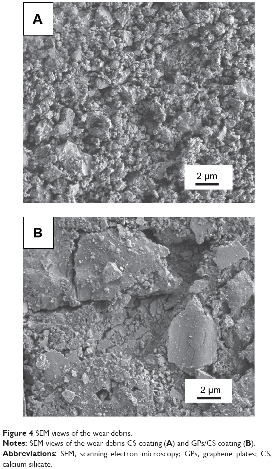 | Figure 4 SEM views of the wear debris. |
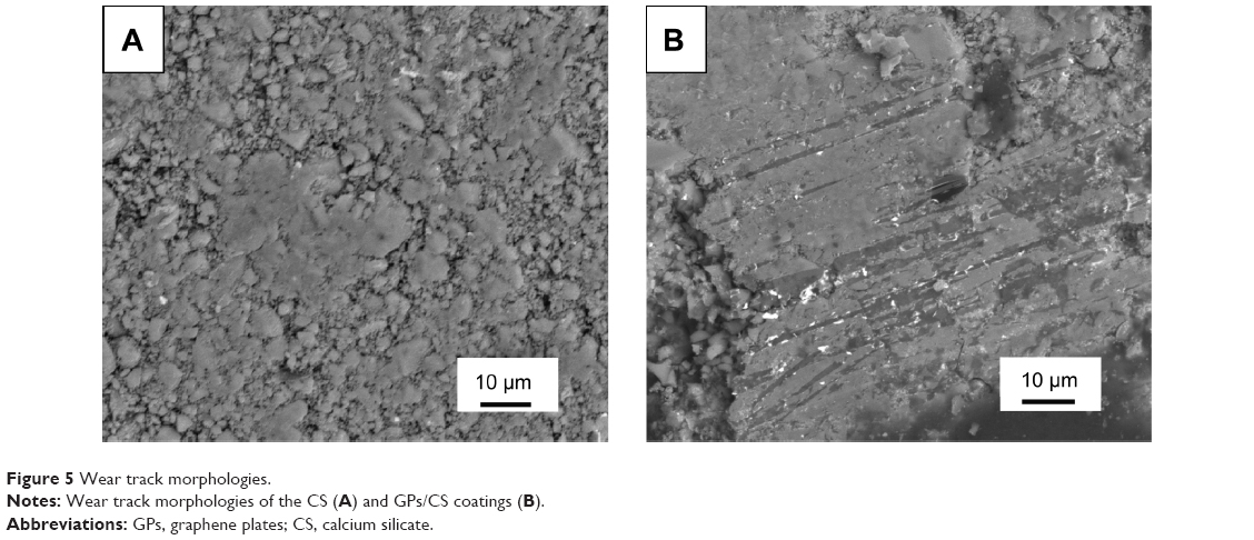 | Figure 5 Wear track morphologies. |
To further study the effects of GPs’ adoption on the microstructure and mechanical properties of the composite coating, TEM was carried out to observe the microstructure of the composite coating. Figure 6 is the representative TEM and high resolution TEM images of the composite coating containing 1.5 wt % GPs. Figure 6A reveals that the GPs were uniformly dispersed in the interface or were semi-enwrapped on the CS grains. Some of the GPs were found to bridge the ceramic grains (as shown in Figure 6B). High resolution TEM results show that the thickness of the GPs was about 10 nm (Figure 6C). Most of the GPs remained whole with a clear interface with CS grains. However, some of the GPs were also exfoliated in the mechanical ball milling or high temperature process of plasma spraying (Figure 6D). The internal structure of the GPs and interface with the CS grains became vague. These results directly demonstrated the increased defects of GPs after plasma spraying and higher D peak strength in the composite coating.
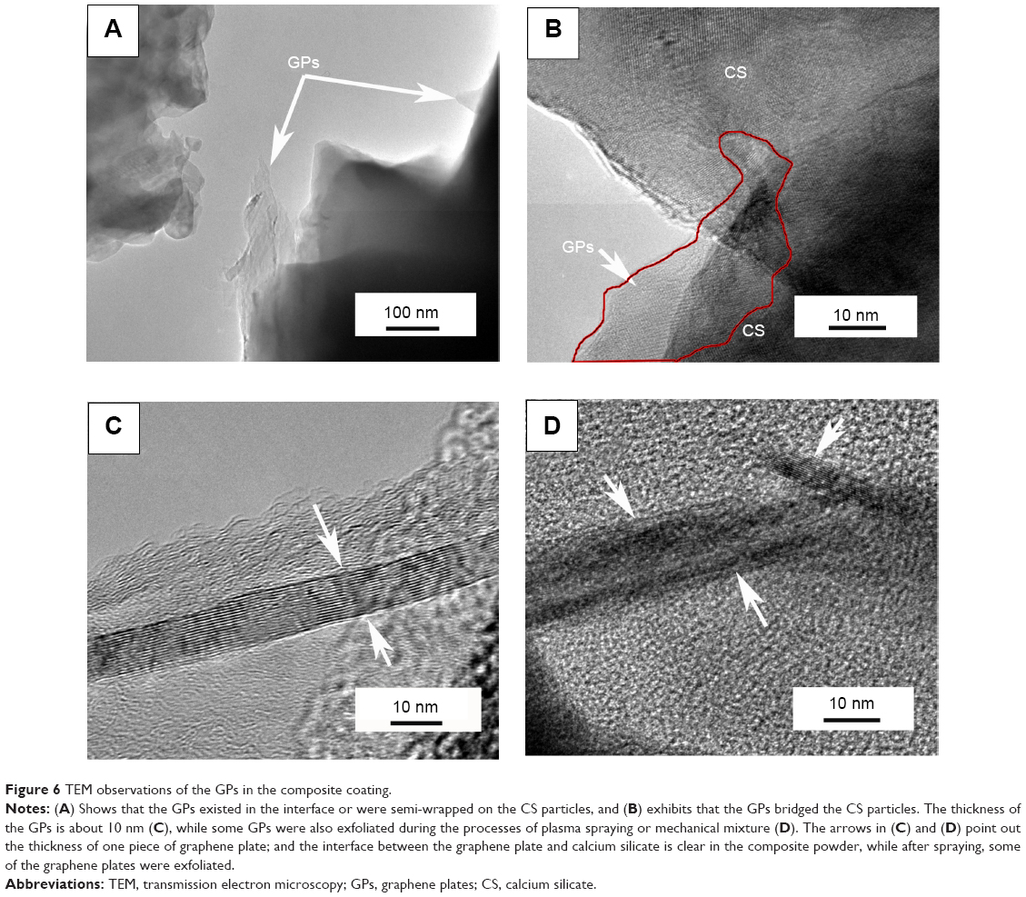 | Figure 6 TEM observations of the GPs in the composite coating. |
A combination of the SEM views and TEM observation demonstrated the good wetting behavior of the GPs with CS ceramic and excellent reinforcement for the improvement of mechanical properties. The uniform dispersion and high surface area of GPs impart uniform sites for energy release and high fracture toughness of the coating, and therefore the relatively high wear resistance. Kvetková et al also reported that the GPs’ adoption was beneficial to the crack deflection, slowing down of crack propagation, crack bridging, and dissipation of crack energy. 22
Biocompatibility evaluation in vivo
In the earlier paper, we demonstrated the good in vitro biological performance of the GPs’ reinforced CS coating.29 The proliferation and osteogenesis-related genes’ (ALP, OC, OPN) expression of hMSCs on the GPs/CS coating was apparently higher than those on the Ti controls, and showed similar trends with the CS coating. In the present work, we further evaluated the in vivo biocompatibility of the composite coating. Our results show that the two coatings exhibited similarly excellent capability for the stimulation of new bone formation. The gaps between the implant and host bone tissue became progressively narrower over the implantation time. After implantation for 1 month, most of the pores on the implant surface were occupied by the bone tissue. The newly formed bone tissues were in direct contact with the coatings. However, some coating fragments could be found in the interface of the CS coating and bone tissues (as shown in Figure 7), while this kind of fragments were very little in the interface of GPs/CS coating and bone tissues. It may be explained by the increased stability of the GPs/CS coating as the reinforcement of GPs. The BIC values analyzed by the histological images were 43.5%±6.2% for GPs/CS coating and 39.8%±8.7% for CS coating. No significant difference was found between the two kinds of coating implants.
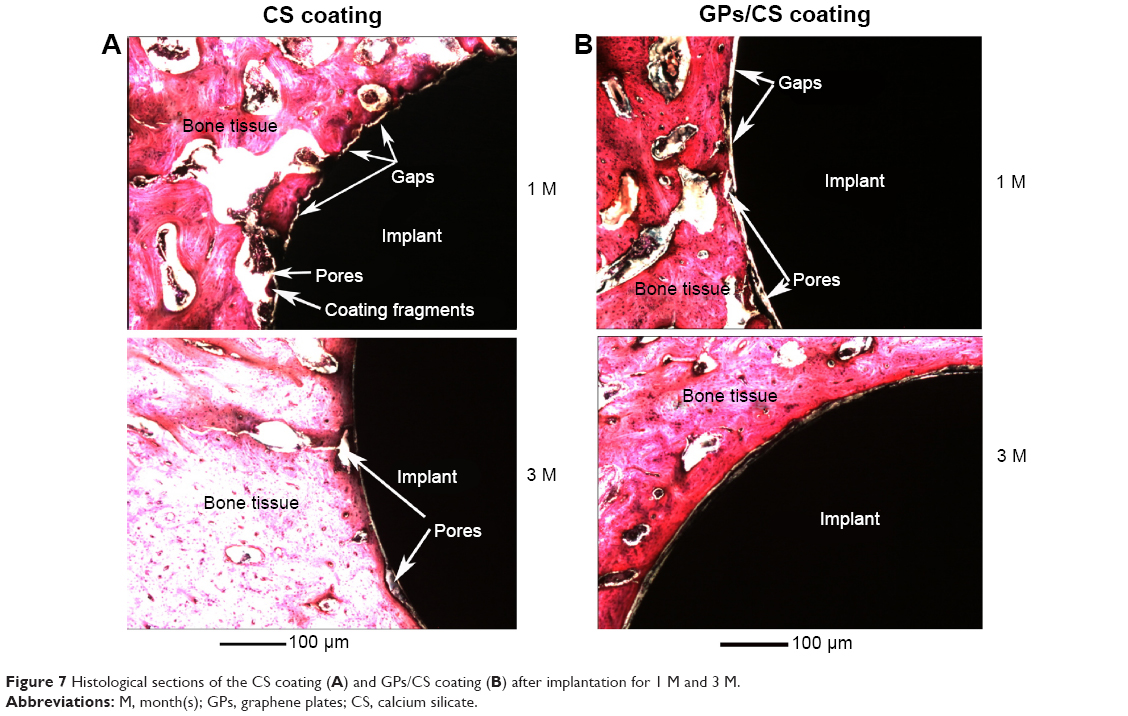 | Figure 7 Histological sections of the CS coating (A) and GPs/CS coating (B) after implantation for 1 M and 3 M. |
After 3 months’ implantation, pores in the interface of the implants and host bone tissue became less and pore size became smaller. Newly developed bone nearly filled all of the gaps between implants and host bone tissue. Very small pores could still be found in the interface of the CS coating and host bone, while those in the GPs/CS coating interface were even less. The measured BIC values were 84.3%±7.4% for GP/CS coating and 79.6%±9.4% for CS coating.
Conclusion
CS reinforced with 1.5 wt % GPs was prepared by vacuum plasma spraying technology. SEM and TEM results showed that the GPs survived the hot process of plasma spraying well, and were homogenously distributed in the CS grains’ interface or enwrapped on the particles. Raman analysis demonstrated that the defects in GPs obviously increased after plasma spraying. The GPs/CS composite coating showed significantly increased wear resistance compared to the pure CS coating. The removing mechanism of the CS coating was mainly abrasive or brittle fracture, while the adoption of GPs effectively improved the particle interfacial bonding and mitigated the brittle facture dramatically. The composite coating not only possesses much higher wear resistance than that of the pure CS coating, but also good biocompatibility in vivo. The BIC ratio reached 84.3%±7.4% after 3 months’ implantation.
Acknowledgment
This work was supported by the National Natural Science Foundation of China (grant number 51172264).
Disclosure
The authors report no conflicts of interest in this work.
References
Walker PS, Schneeweis D, Murphy S, Nelson P. Strains and micromotions of press-fit femoral stem prostheses. J Biomech. 1987;20(7):693–702. | ||
Riues J, Rabbe L. Fretting wear corrosion of surgical implants alloys: effects of ion implantation and ion nitriding on fretting behavior of metals/PMMA contact. In: Sudanshan TS, Jeandin M, editors. Surface Modification Technologies VIII. The Institute of Materials; 1995:43–52. | ||
Pilliar RM. Cementless implant fixation – toward improved reliability. Orthop Clin N Am. 2005;36(1):113–119. | ||
Pilliar RM. Porous-surfaced metallic implants for orthopedic applications. J Biomed Mater Res. 1987;21(A1 Suppl):1–33. | ||
Lin H, Xu HC, Zhang XD, de Groot K. Tensile tests of interface between bone and plasma-sprayed HA coating-titanium implant. J Biomed Mater Res. 1998;43(2):113–122. | ||
Ferraz MP, Santos JD, Afonso A, Vasconcelos M, Monteiro FJ. Histological studies of double layer HA/CaO-P2O5 glass plasma sprayed coatings using rabbit model. Bioceramics. 2000;192-1:449–452. | ||
Cao Y, Lin Q, Ying XQ, et al. The effect of cell behavior on plasma sprayed HA coatings with different post treatment. Bioceramics 18. 2006;(309–311):705–708. | ||
Inagaki M, Yokogawa Y, Kameyama T. The influence of processing parameters on the HA products of RF thermal plasma-sprayed HA/Ti composite coatings. Bioceramics. 2000;(192–195):195–198. | ||
Xie YT, Liu XY, Ding CX, Chu PK. Bioconductivity and mechanical properties of plasma-sprayed dicalcium silicate/zirconia composite coating. Materials Science and Engineering: C. 2005;25(4):509–515. | ||
Xue WC, Liu XY, Zheng XB, Ding CX. In vivo evaluation of plasma-sprayed wollastonite coating. Biomaterials. 2005;26(17):3455–3460. | ||
Carlisle EM. Silicon as an essential trace-element in animal nutrition. Ciba Found Symp. 1986;121:123–139. | ||
Keeting PE, Oursler MJ, Wiegand KE, Bonde SK, Spelsberg TC, Riggs BL. Zeolite-a increases proliferation, differentiation, and transforming growth-factor-beta production in normal adult human osteoblast-like cells-invitro. J Bone Miner Res. 1992;7(11):1281–1289. | ||
Perullini M, Rivero MM, Jobbagy M, Mentaberry A, Blimes SA. Plant cell proliferation inside an inorganic host. J Biotechnol. 2007;127(3):542–548. | ||
Nayab SN, Jones FH, Olsen I. Effects of calcium ion implantation on human bone cell interaction with titanium. Biomaterials. 2005;26(23):4717–4727. | ||
Hanawa T, Kamiura Y, Yamamoto S, et al. Early bone formation around calcium-ion-implanted titanium inserted into rat tibia. J Biomed Mater Res. 1997;36(1):131–136. | ||
Jinno T, Kirk SK, Morita S, Goldberg VM. Effects of calcium ion implantation on osseointegration of surface-blasted titanium alloy femoral implants in a canine total hip arthroplasty model. J Arthroplasty. 2004;19(1):102–109. | ||
Palanivelu R, Kalainathan S, Kumar AR. Characterization studies on plasma sprayed (AT/HA) bi-layered nano ceramics coating on biomedical commercially pure titanium dental implant. Ceramics International. 2014;40(6):7745–7751. | ||
Poot M, van der Zant HS. Nanomechanical properties of few-layer graphene membranes. Appl Phys Lett. 2008;92(6). | ||
Lee C, Wei XD, Li QY, Carpick R, Kysar JW, Hone J. Elastic and frictional properties of graphene. Phys Status Solidi B. 2009;246(11–12):2562–2567. | ||
Lee C, Wei XD, Kysar JW, Hone J. Measurement of the elastic properties and intrinsic strength of monolayer graphene. Science. 2008;321(5887):385–388. | ||
Liu J, Yan HX, Reece MJ, Jiang K. Toughening of zirconia/alumina composites by the addition of graphene platelets. J Eur Ceram Soc. 2012;32(16):4185–4193. | ||
Kvetkova L, Duszova A, Hvizdos P, Dusza J, Kun P, Balazsi C. Fracture toughness and toughening mechanisms in graphene platelet reinforced Si3N4 composites. Scripta Mater. 2012;66(10):793–796. | ||
Walker LS, Marotto VR, Rafiee MA, Koratkar N, Corral EL. Toughening in graphene ceramic composites. ACS Nano. 2011;5(4):3182–3190. | ||
Zhang L, Liu WW, Yue CG, et al. A tough graphene nanosheet/hydroxyapatite composite with improved in vitro biocompatibility. Carbon. 2013;61:105–115. | ||
Shen H, Zhang LM, Liu M, Zhang ZJ. Biomedical applications of graphene. Theranostics. 2012;2(3):283–294. | ||
Sanchez VC, Jachak A, Hurt RH, Kane AB. Biological interactions of graphene-family nanomaterials: an interdisciplinary review. Chem Res Toxicol. 2012;25(1):15–34. | ||
Kalbacova M, Broz A, Kong J, Kalbac M. Graphene substrates promote adherence of human osteoblasts and mesenchymal stromal cells. Carbon. 2010;48(15):4323–4329. | ||
Kandiah K, Muthusamy P, Mohan S, Venkatachalam R. TiO2-graphene nanocomposites for enhanced osteocalcin induction. Mat Sci Eng C-Mater. 2014;38:252–262. | ||
Xie YT, Li HQ, Zhang C, Gu X, Zheng XB, Huang LP. Graphene-reinforced calcium silicate coatings for load-bearing implants. Biomed Mater. 2014;9(2):025009. | ||
Huang Y, Jin XG, Zhang XL, et al. In vitro and in vivo evaluation of akermanite bioceramics for bone regeneration. Biomaterials. 2009;30(28):5041–5048. | ||
Xie YT, Ao HY, Xin SG, Zheng XB, Ding CX. Enhanced cellular responses to titanium coating with hierarchical hybrid structure. Mat Sci Eng C-Mater. 2014;38:272–277. | ||
Alcocer-Cuaron C, Rivera AL, Castano VM. Hierarchical structure of biological systems A bioengineering approach. Bioengineered. 2014;5(2):73–79. | ||
Ferrari AC. Raman spectroscopy of graphene and graphite: Disorder, electron-phonon coupling, doping and nonadiabatic effects. Solid State Commun. 2007;143(1–2):47–57. | ||
Ferrari AC, Robertson J. Interpretation of Raman spectra of disordered and amorphous carbon. Phys Rev B. 2000;61(20):14095–14107. | ||
Prevost TC, Abrams KR, Jones DR. Hierarchical models in generalized synthesis of evidence: an example based on studies of breast cancer screening. Stat Med. 2000;19(24):3359–3376. | ||
Xia Z, Riester L, Curtin WA, et al. Direct observation of toughening mechanisms in carbon nanotube ceramic matrix composites. Acta Mater. 2004;52(4):931–944. | ||
Andrews R, Jacques D, Qian D, Dickey EC. Purification and structural annealing of multiwalled carbon nanotubes at graphitization temperatures. Carbon. 2001;39(11):1681–1687. | ||
Ci LJ, Zhu HW, Wei BQ, Xu CL, Wu DH. Annealing amorphous carbon nanotubes for their application in hydrogen storage. Appl Surf Sci. 2003;205(1):39–43. | ||
Huang W, Wang Y, Luo GH, Wei F. 99.9% purity multi-walled carbon nanotubes by vacuum high-temperature annealing. Carbon. 2003;41(13):2585–2590. | ||
Delpeux-Ouldriane S, Szostak K, Frackowiak E, Beguin F. Annealing of template nanotubes to well-graphitized multi-walled carbon nanotubes. Carbon. 2006;44(4):814–818. | ||
Pioletti DP, Takei H, Kwon SY, Wood D, Sung KL. The cytotoxic effect of titanium particles phagocytosed by osteoblasts. J Biomed Mater Res. 1999;46(3):399–407. | ||
Haynes DR, Hay SJ, Rogers SD, Ohta S, Howie DW, Graves SE. Regulation of bone cells by particle-activated mononuclear phagocytes. J Bone Joint Surg Br. 1997;79(6):988–994. | ||
Neale SD, Haynes DR, Howie DW, Murray DW, Athanasou NA. The effect of particle phagocytosis and metallic wear particles on osteoclast formation and bone resorption in vitro. J Arthroplasty. 2000;15(5):654–662. | ||
Lohmann CH, Dean DD, Koster G, et al. Ceramic and PMMA particles differentially affect osteoblast phenotype. Biomaterials. 2002;23(8):1855–1863. | ||
Wijenayaka AK, Colby CB, Atkins GJ, Majewski P. Biomimetic hydroxyapatite coating on glass coverslips for the assay of osteoclast activity in vitro. J Mater Sci Mater Med. 2009;20(7):1467–1473. | ||
Goodman SB, Ma T. Cellular chemotaxis induced by wear particles from joint replacements. Biomaterials. 2010;31(19):5045–5050. |
 © 2015 The Author(s). This work is published and licensed by Dove Medical Press Limited. The
full terms of this license are available at https://www.dovepress.com/terms
and incorporate the Creative Commons Attribution
- Non Commercial (unported, 3.0) License.
By accessing the work you hereby accept the Terms. Non-commercial uses of the work are permitted
without any further permission from Dove Medical Press Limited, provided the work is properly
attributed. For permission for commercial use of this work, please see paragraphs 4.2 and 5 of our Terms.
© 2015 The Author(s). This work is published and licensed by Dove Medical Press Limited. The
full terms of this license are available at https://www.dovepress.com/terms
and incorporate the Creative Commons Attribution
- Non Commercial (unported, 3.0) License.
By accessing the work you hereby accept the Terms. Non-commercial uses of the work are permitted
without any further permission from Dove Medical Press Limited, provided the work is properly
attributed. For permission for commercial use of this work, please see paragraphs 4.2 and 5 of our Terms.