Back to Journals » Medical Devices: Evidence and Research » Volume 14
Device for Controlling Stimulus Self-Application During Autonomic Nervous System Tests
Authors Żyliński M, Niewiadomski W ![]() , Cybulski G
, Cybulski G ![]() , Gąsiorowska A
, Gąsiorowska A ![]()
Received 5 January 2021
Accepted for publication 29 April 2021
Published 1 June 2021 Volume 2021:14 Pages 165—172
DOI https://doi.org/10.2147/MDER.S300384
Checked for plagiarism Yes
Review by Single anonymous peer review
Peer reviewer comments 3
Editor who approved publication: Dr Scott Fraser
Marek Żyliński,1 Wiktor Niewiadomski,2 Gerard Cybulski,1 Anna Gąsiorowska2
1Institute of Metrology and Biomedical Engineering, Faculty of Mechatronics, Warsaw University of Technology, Warsaw, Poland; 2Mossakowski Medical Research Institute, Polish Academy of Sciences, Warsaw, Poland
Correspondence: Marek Żyliński
Institute of Metrology and Biomedical Engineering, Faculty of Mechatronics, Warsaw University of Technology, ul. św. Andrzeja Boboli 8, Warszawa, 02-525, Poland
Tel +48 22 2348387
Email [email protected]
Abstract: Assessment of autonomic nervous system (ANS) functioning may be performed non-invasively using autonomic tests which are based on evaluation of response of cardiovascular system to the applied stimuli, such as increased air pressure during Valsalva maneuver, skeletal muscle contraction during static handgrip or deep slow breathing. The cardiovascular response depends, besides ANS reaction and test protocol, also on the way stimulus is self-applied by the test subject. We present a versatile device for controlling stimulus self-application during three ANS tests: Valsalva maneuver, static handgrip, and deep breathing. It integrates two different gauges and a pace setter for breathing into one device. The core of the device is a linear LED display which, using green, yellow, and red diodes, informs the subject about the correctness of self-application of respective stimulus. The settings of the device can be adjusted to the needs of the protocol chosen. The device can record the duration of mouth air pressure or the force produced by the subject during ANS tests, which assures correctness of the tests, thus allowing to track individual variability changes in the response to the test. The device was verified during ANS tests and its use was intuitive for patients, reducing the time needed for training before tests and decreasing the effort of the physician.
Keywords: biomedical equipment, Ewing’s battery, autonomic nervous system tests
Background
Ewing’s Battery – Autonomic Nervous System Tests
The autonomic nervous system (ANS) is a part of the nervous system which innervates the heart, smooth muscles, and glands. ANS activity is independent of our will.1 Specifically, ANS regulates heart rate, contractility of the heart muscle and diameter of blood vessels; therefore, short-term blood pressure regulation is mainly controlled by ANS.2
Impaired function of ANS may result from damage, eg, in diabetes (diabetic neuropathy),3 intoxication (botulinum), neurodegenerative diseases (eg, Parkinson’s disease)4 or may be congenital.5
Assessment of ANS functioning can be done non-invasively with use of autonomic tests which are based on evaluation of response of the cardiovascular system to applied stimuli. Ewing et al proposed a set of four tests.6
• Head-up tilt – the transition from supine to standing posture, either performed actively by the patient, or passively, using a tilt table. The immediate heart-rate response to standing up or tilt-up and, separately, arterial pressure response are both evaluated.
•Valsalva maneuver – the patient blows into a mouthpiece trying to maintain mouth air pressure at 40 mmHg level for 15 seconds. During Valsalva maneuver, arterial pressure initially rises, then drops and heart rate increases. Moreover, after release of strain, blood pressure can overshoot its resting level and the heart rate slows in response. Both heart rate and arterial pressure changes are evaluated.
•Deep breathing – it is typically performed at six breaths per minute. Heart rate accelerates and decelerates cyclically to the rhythm of breathing and the magnitude of heart rate changes is evaluated.
•Handgrip – sustained handgrip is maintained at 30% of maximum voluntary contraction. During handgrip, arterial pressure rises, and the magnitude of this rise is evaluated.
Evaluation of tests from Ewing’s battery relies on changes in heart rate or arterial pressure. For example, in case of deep breathing, ratio between maximum and minimum RR interval is examined; in case of handgrip, increase of blood pressure during exercise is evaluated. Ratio close to 1 of RR intervals during deep breathing test or attenuated rise in blood pressure during handgrip may indicate ANS dysfunction. The cardiovascular response depends, aside from the subject’s characteristics,7 also on the magnitude and duration of the stimuli applied.
The rise of arterial pressure and change in heart rate during head-up tilt is proportional to the angle of tilting.8 Heart rate for small tilt angle (<30°) changes insignificantly, by approximately 5%. For 53° and 70° tilt angles, heart rate may increase up to 20 and 40%, respectively.
The value of mouth air pressure during the Valsalva maneuver influences amplitude of arterial pressure response.9 The authors found an increase in the amplitude of systolic blood pressure associated with an increase in Valsalva pressure.
The amplitude of changes in heart rate increases with the increase of depth of breath.10
During a handgrip, it is essential to maintain its strength at the predefined percentage of the maximum voluntary contraction (MVC). Sakakibara et al found that for contractions lower than 10% of MVC, new stable levels of cardiovascular response will be established.11 For contractions performed with 20% to 60% of MVC, cardiovascular response will rise parallel to the duration of the effort, until exhaustion and refusal to continue. For contractions greater than 60% MVC, handgrip can be maintained for less than 1 minute. The conclusion is that an uncontrolled strength application may invalidate this test.
Apart from the impact of the magnitude of the stimulus, the time course of stimulus may also influence cardiovascular response, and consequently influence the evaluation of the autonomic test. Figure 1 presents two consecutive Valsalva maneuvers. Both were performed at the correct level of mouth air pressure but during the first one, a transient dip in mouth air pressure occurred, while the second maneuver was performed correctly. Responses to both maneuvers were significantly different; the first one was clearly weaker, which might be interpreted as a diminished reactivity of ANS. However, once the maneuver is performed correctly, expected response, ie, the rise in heart rate and a decrease in arterial pressure, is clearly present.
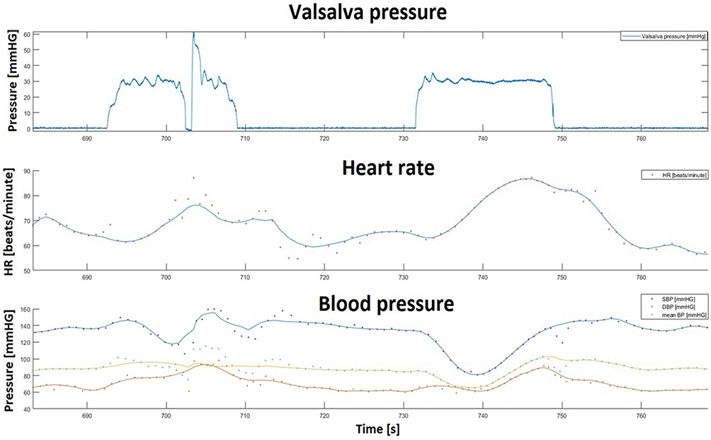 |
Figure 1 Example of incorrectly (693 −709 s) and correctly (732 −748 s) performed Valsalva maneuvers and resulting heart rate and arterial pressure responses. During the incorrectly performed maneuver, a 70-year-old man was maintaining correct mouth air pressure except for a short period, when this pressure dropped to 0. During correctly performed maneuver, the mouth air pressure was maintained throughout the test. Heart rate rise and arterial pressure drop were lower during the incorrectly performed maneuver in comparison to the correctly performed one, rendering incorrect assessment of magnitude of ANS reaction. |
Controlling the way stimuli are applied during autonomic tests seems to be essential if not indispensable. Lack of such control renders the outcome of these tests unreliable, even misleading and precludes inter-individual comparisons, thus invalidating the process of monitoring progression of changes in ANS functioning, for instance.
Methods of Stimulus Control in Ewing’s Battery
ANS tests in Ewing’s battery require patients’ cooperation. The patient should breathe at the preset frequency, should perform grip with a predetermined and unchanging strength, and should attain and maintain required mouth air pressure during the Valsalva maneuver. Correct execution of tests by the patient is crucial and must be controlled. Spallone et al12 pointed out that the reliability of the ANS test depends on its standardization. Authors recommend familiarizing patients with the test protocol and the execution of each test, the process of verification of correct execution, and advising them on how to avoid disturbing factors.
In papers on the Ewing’s ANS tests battery, standardization and stimulus control issues are rarely mentioned, sometimes even the description of how the tests were performed is missing, including the level of stimuli used, in some papers13,14 only Ewing’s paper6 is cited, without any further information. It is a common practice not to disclose the information on the devices or methods used for stimuli control.
In addition, the outcomes of autonomic tests performed in different laboratories may vary due to varying protocols (Table 1). For this reason, comparing results from different laboratories is, in fact, impossible. This issue is not directly relevant to the main topic of our paper; yet we think it proper to draw readers’ attention to this often-ignored issue.
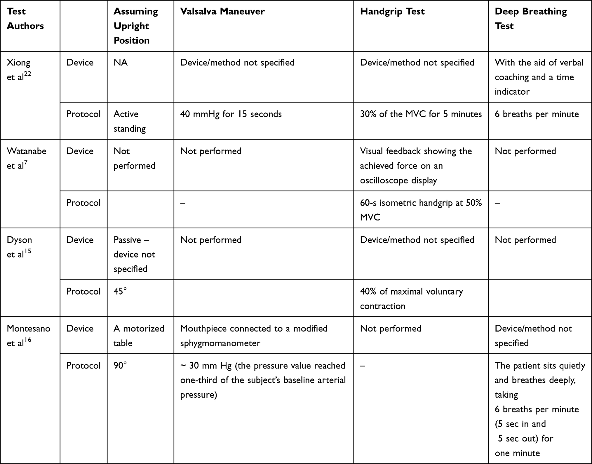 |
Table 1 Exemplary Protocols and Methods Used to Maintain Stimulus at Proper Level During Ewing’s Battery of ANS Tests in Four Studies |
The head-up tilt test was performed as active or passive change of posture. In case of passive head-up tilt, various tilt angles were applied; for instance, 45° by Dyson et al15 or 90° by Montesano et al.16 Often, the time needed to accomplish a passive tilt is not detailed. In case of handgrip, different protocols were applied; handgrip was performed at 30%, 40% or 50% of MVC.
In order to maintain the required mouth air pressure during the Valsalva maneuver, Montesano et al16 asked subjects to monitor a display of an analog manometer. Watanabe et al7 made subjects maintain the required strength during the handgrip by looking at the oscilloscope, which displayed the actual level of force produced by the subject. During deep, slow breathing, the maintenance of breathing frequency was ensured by vocal guidance. The time course of the stimulus applied was not recorded in any of the papers analyzed by us. Similarly, we have not found any description of error margin within which a given stimulus could be qualified as correct. For instance, with respect to the Valsalva maneuver, a 10% error margin for mouth air pressure may be regarded as acceptable, meaning that the subject has to maintain the pressure of between 36 and 44 mmHg, assuming 40 mmHg as the desired level, over the course of the entire test.
Despite the passage of time, the performing of state-of-the-art ANS tests has not changed. In the latest papers using Ewing’s tests17–22 we found the same problems as mentioned previously: varying protocols, different stimulus level or tests’ order. However, it is satisfactory that in almost every paper (besides one17) level and duration of stimulus are mentioned. Only in a few papers18–20 were types of device used to control stimulus mentioned in general terms, eg, aneroid manometer. None of these papers mention method of controlling stimulus. Only Alhamadani et al23 reported stimulus recording, they marked the onset of each inspiration and expiration during deep breathing test.
In this paper we present a device for controlling stimulus self-application during ANS tests. This device is intended: 1) to obviate the need to learn different ways of controlling self-produced stimuli and, thanks to this, 2) to relieve the person tested from the additional stress incurred by the need to learn and use these different ways, 3) to better control the quality of self-produced stimuli, 4) to allow post hoc inspection of the correctness of self-produced stimuli with regard to their timing and magnitude. The overarching goal was to improve the reliability and reproducibility of autonomic tests.
Device for Controlling Stimulus Self-Application During ANS Tests
Device Operation During ANS Tests
For each test in Ewing’s battery, different equipment is needed, and the subject must be familiarized with each one. Besides being time consuming, it may also be confusing for the subject.
Spallone et al11 proposed to introduce a system which: a) provides subject information needed to correctly perform the test, b) enables physician to assess the quality of subjects’ performance and thus the validity of the results. In this paper, we describe the device that fulfills these objectives. This device is used routinely in our lab.
The main idea was to use a single display, which enables the subject to act in the same way in order to maintain the required level of stimulus: mouth air pressure in case of Valsalva maneuver, muscle strength in case of handgrip, or to maintain the required pattern of stimulus: pace of breathing in case of deep breathing. The subject, during these three ANS tests, is not confronted with different devices like manometer, force gauge or metronome, but with only one display and should react in the same or similar way (Figure 2).
 |
Figure 2 Information needed to perform the test correctly is shown on the LED display, in the same way during different ANS tests. The most important advantage of such a solution is that the subject is confronted with the same way of conveying information from measuring device trying to get the desired level of different stimuli or pattern of activity which is conceptualized in the same way. This removes the need to familiarize a subject with different measuring devices used in various ANS tests and to teach them about how the desired goal is presented in particular measuring devices. |
The main element of the device is an LED display. It consists of a line of 25 small, 5mm rectangular LEDs. In the middle of the line, there are 3 green diodes, flanked by yellow ones on both sides, and by red ones on two ends of the line.
During handgrip and Valsalva maneuver, the stimulus level, ie, the muscle force or the mouth air pressure produced by the subject respectively, is processed by the device. If the stimulus level is within the allowable range, one of the green LEDs is on, if it is slightly out of range, one of the yellow LEDs is on. If it is substantially off the range, one of the red LEDs is on. LED display is oriented vertically. By convention, if LEDs below green ones are on, they signal stimulus level lower than required, if LEDs above green ones are on, they signal stimulus level higher than required.
Before commencing an ANS test, the tested person is informed of how the display conveys information on whether self-applied stimulus is correct or is off-target. The task of the patient is to keep the green LEDs on or increase or decrease the level of self-produced stimulus to bring it back to the desired range, ie, make the green LED switch on, and switch off any yellow or red LEDs.
During the deep breathing test, LEDs successively turn on and off at a set pace, in such a way that when the subject should inhale, successively more and more LEDs are turned on, starting from the lowest LED. When the subject should exhale, more and more LEDs are turned off, starting from the highest one. The subject should adjust the duration of his inhaling and exhaling to what is shown on the display. By default, the breathing rate is set at 6 breaths per minute, but the physician can set it differently.
The device is equipped with a mouthpiece, a built-in air pressure sensor, and an analog input, to which analog output from a handgrip dynamometer may be connected. Typically, handgrip should be performed with strength corresponding to 30% of strength developed during maximal voluntary contraction (MVC), therefore the value of MVC has to be settled before the test. For this purpose, the subject performs MVC and the device stores the maximum value of the force produced by him. Next, it calculates 30% of this maximum value and sets this value as the desired strength to be maintained by the subject during handgrip.
The device is controlled with a computer application, with which it communicates via a USB interface. A physician can easily switch between ANS tests and choose the desired stimulus level (ie, breathing rate, Valsalva pressure, % MVC).
Device Design
Figure 3 presents a block diagram of the device. For the execution of digital control, we chose the Atmega32u4-AU (Microchip Technology Inc., Arizona, USA) microcontroller. The main advantage of it is a built-in USB interface, which is used to communicate with the computer and to power the device. The microcontroller also contains ADC and sufficient number of I/O pins (we use 20 of them: 5 serve as input for microswitches, 5 are used to control LEDs which indicate the status of the device, and 10 I/O pins are used to operate the LED display).
 |
Figure 3 Block diagram of the device. Device consists of two measurement channels: one connected to the built-in pressure sensor and another one connected to the external sensor (dynamometer). The microcontroller converts an analog signal to visual information, ie, the position of turned-on LEDs on the display. The USB interface is used to communicate with a computer. The device can operate as a metronome, air pressure or force display. |
A standard USB serial port protocol is used for communication between the device and a computer. A computer can send a text command that sets the device into one of four modes (deep breathing, Valsalva maneuver, handgrip test, and handgrip force setting). The command can also set any breathing rate, any % of MVC, and any Valsalva pressure.
The LED display consists of 5 modules. Figure 4 presents a diagram of a single LED display module. Left hand pins (1–5) are used to choose one of 5 modules. Right hand pins (A – E) are used to choose one of 5 LEDs within the module. Therefore, the combination of high voltage on one of 1–5 pins and low voltage on one of A–E pins turns on one and only one LED out of 25. For instance, in order to turn on LED 1 in module 1, pin 1 has to be set high, pins 2–5 low, pin A (common for all modules) has to be set low and pins B–E (also common to all modules each) have to be set high. In this way, 52 combinations are produced by 10 pins. We used 25 rectangle LEDs, 5 mm x 5 mm, red, yellow, and green ones. Atmega can deliver a 25 mA current, which is enough to power-up LEDs.
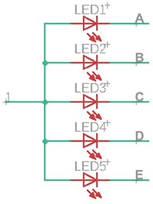 |
Figure 4 Electronic scheme of one LED display module (one of 5 similar in modules in the whole display). To turn LED on, for instance LED1 in module no. 1, pin 1 must be set high and A low, B–E pins must be set high, so using 10 pins, divided in two 5 pin sets, ie, (1−5) and (A–B) the device can control 25 (ie, 52) LEDs. |
The device has a control panel which allows the user to change the state of the device by pushing a button. The panel has 5 buttons (one extra button for custom state, eg, Valsalva at lower pressure level). The panel features 5 LEDs that indicate the state of the device.
The device has two measurement circuits: one dedicated for the external dynamometer and one for the built-in pressure sensor. They adjust the signal level and input impedance to the requirements of Atmega’s ADC. The dynamometer circuit has a high input impedance and a 4x amplification. The frequency range was limited to 43 Hz with an active low-pass filter. TL074 IC (Texas Instruments, Texas, USA) operational amplifiers were used.
To measure mouth air pressure, MPX53DP (NXP Semiconductors, Netherlands) was chosen. The sensor can measure the pressure of up to 375 mmHg and can work with a single 5V supply voltage. The sensor was connected to the mouthpiece with a 6mm silicone hose. In the prototype device, we used a trumpet mouthpiece.
The difference signal from the sensor is amplified and converted to ground signal with instrumentation amplifier INA126 (Texas Instruments, Texas, USA). Next, the signal is amplified and filtered (5,4 amplification, frequency limit up to 43 Hz). The BNC female connector outputs the signal. The pressure measurement range was limited to 10–60 mmHg.
The calibration of pressure sensor was performed by applying pressure (measured with a mercury sphygmomanometer) and measuring the voltage on the BNC output. The calibration function (Figure 5) was stored in the device memory and is used during Valsalva maneuver. Calibration should be performed once per quarter.
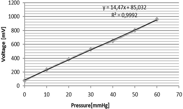 |
Figure 5 Calibration line of pressure measurement. Voltage output is calibrated using pressure measured with mercury sphygmomanometer. |
The manufacturing costs of the device is ca. $300±$150, excluding cost of certification. Final cost depends on the scale of production. In case of short series, the work cost per piece will be higher; in case of longer series, most of production stages may be automatized. The parts of the device are rather cheap, the most expensive is pressure sensor (~$10), microcontroller (~$4), and set of LEDs ($5). Costs also encompass PCP, other electronic elements and connectors.
Conclusion
In this paper we present a device which allows control of self-application of stimulus by the subject being tested during three ANS tests: deep breathing, Valsalva maneuver, and static handgrip. The device integrates two gauges (built in air pressure and external muscle force ones) and a pace setter for breathing into one device. Furthermore, it enables one to record the time course of mouth air pressure or the muscle force produced by the subject during ANS tests.
Self-application of stimulus, as is the case during Valsalva maneuver, handgrip and deep breathing test brings a risk of generating improper stimulus which may change the outcome of the test. The device we described is aimed toward: 1) making it easier to generate correct stimulus by simplifying and unifying the way a test person controls stimulus generation, 2) reducing the stress involved with the task to perform self-stimulation correctly, as such stress may be an additional and uncontrollable stimulus, effecting test outcome. On the side of a person supervising the test the device enables 3) post hoc checking whether the stimulus is of acceptable quality and eventual rejection of tests’ outcome if stimulus deviates in unacceptable way from the assumed one. In addition, by making correct self-application of the stimulus easier, the device 4) shortens the time needed to give instruction, which shortens overall time devoted to performing Ewing’s test battery. The device has been used for research and has been accepted both by persons tested and those supervising the tests. We believe that this device will help improve the reliability and reproducibility of autonomic nervous system tests.
Acknowledgments
The study was supported by the research grant Warsaw University of Technology.
Disclosure
The authors report no conflicts of interest in this work.
References
1. Sylwanowicz W, Michajlik A, Ramotowski W. Anatomia i fizjologia człowieka: podręcznik dla średnich szkół medycznych. Państwowy Zakład Wydawnictw Lekarskich; 1985.
2. Stewart JM. Mechanisms of sympathetic regulation in orthostatic intolerance. J Appl Physiol. 2012;113(10):1659–1668. doi:10.1152/japplphysiol.00266.2012
3. Low PA, Benrud-Larson LM, Sletten DM, et al. Autonomic symptoms and diabetic neuropathy: a Population-Based Study. Diabetes Care. 2004;27(12):2942–2947. doi:10.2337/diacare.27.12.2942
4. Turkka JT, Tolonen U, Myllylä VV. Cardiovascular reflexes in Parkinson’s disease. Eur Neurol. 1987;26(2):104–112. doi:10.1159/000116319
5. Weese‐Mayer DE, Berry‐Kravis EM, Zhou L, et al. Idiopathic congenital central hypoventilation syndrome: analysis of genes pertinent to early autonomic nervous system embryologic development and identification of mutations in PHOX2b. Am J Med Genet A. 2003;123(3):267–278. doi:10.1002/ajmg.a.20527
6. Ewing D, Clarke B. Diagnosis and management of diabetic autonomic neuropathy. BMJ. 1982;285(6346):916. doi:10.1136/bmj.285.6346.916
7. Watanabe K, Ichinose M, Tahara R, Nishiyasu T. Individual differences in cardiac and vascular components of the pressor response to isometric handgrip exercise in humans. Am J Physiol Heart Circ Physiol. 2014;306(2):H251–H260. doi:10.1152/ajpheart.00699.2013
8. Laszlo Z, Rossler A, Hinghofer-Szalkay H. Cardiovascular and hormonal changes with different angles of head-up tilt in men. Physiol Res. 2001;50(1):71–82.
9. Niewiadomski W, Pilis A, Strasz A, et al. In aged men, central vessel transmural pressure is reduced by brief Valsalva manoeuvre during strength exercise. Clin Physiol Funct Imaging. 2014;34(3):191–198. doi:10.1111/cpf.12080
10. Song H-S, Lehrer PM. The effects of specific respiratory rates on heart rate and heart rate variability. Appl Psychophysiol Biofeedback. 2003;28(1):13–23. doi:10.1023/A:1022312815649
11. Sakakibara Y, Honda Y. Cardiopulmonary responses to static exercise. J Physiol Anthropol. 1990;9(2):153–161. doi:10.2114/ahs1983.9.153
12. Spallone V, Bellavere F, Scionti L, et al. Recommendations for the use of cardiovascular tests in diagnosing diabetic autonomic neuropathy. Nutr Metab Cardiovasc Dis. 2011;21(1):69–78. doi:10.1016/j.numecd.2010.07.005
13. Nayani S, Sreedharan SE, Namboodiri N, Sarma PS, Sylaja P. Autonomic dysfunction in first ever ischemic stroke: prevalence, predictors and short term neurovascular outcome. Clin Neurol Neurosurg. 2016;150:54–58. doi:10.1016/j.clineuro.2016.08.022
14. Howorka K, Pumprla J, Schabmann A. Optimal parameters of short-term heart rate spectrogram for routine evaluation of diabetic cardiovascular autonomic neuropathy. J Auton Nerv Syst. 1998;69(2–3):164–172. doi:10.1016/S0165-1838(98)00015-0
15. Dyson KS, Shoemaker JK, Arbeille P, Hughson RL. Modelflow estimates of cardiac output compared with Doppler ultrasound during acute changes in vascular resistance in women. Exp Physiol. 2010;95(4):561–568. doi:10.1113/expphysiol.2009.050815
16. Montesano M, Miano S, Paolino MC, et al. Autonomic cardiovascular tests in children with obstructive sleep apnea syndrome. Sleep. 2010;33(10):1349–1355. doi:10.1093/sleep/33.10.1349
17. Kapelios CJ, Bonou M, Barmpagianni A, et al. Early left ventricular systolic dysfunction in asymptomatic patients with type 1 diabetes: a Single-Center, Pilot Study. J Diabetes Complications. 2021;35(6):107913. doi:10.1016/j.jdiacomp.2021.107913
18. Dhumad MM, Hamdan FB, Khudhair MS, Al-Matubsi HY. Correlation of staging and risk factors with cardiovascular autonomic neuropathy in patients with type II diabetes mellitus. Sci Rep. 2021;11(1):1–11. doi:10.1038/s41598-021-80962-w
19. Rivera AL, Estańol B, Macias-Gallardo JJ, et al. Cardiovascular dysautonomia in Achalasia patients: blood pressure and heart rate variability alterations. PLoS One. 2021;16(3):e0248106. doi:10.1371/journal.pone.0248106
20. Sushma S, Rao MY, Aslam SM. Assessment of functions of the autonomic nervous system in the elderly with different comorbid factors. J Neurosci Rural Pract. 2021;12(1):80. doi:10.1055/s-0040-1718854
21. Townsend L, Moloney D, Finucane C, et al. Fatigue following COVID-19 infection is not associated with autonomic dysfunction. PLoS One. 2021;16(2):e0247280. doi:10.1371/journal.pone.0247280
22. Xiong L, Tian G, Leung H, et al. Autonomic dysfunction as measured by Ewing battery test to predict poor outcome after acute ischaemic stroke. Hong Kong Med J. 2019;25(4 Supplement 5):9–11.
23. Alhamadani NN, Alassady EH. Effect of green coffee supplement on autonomic cardiovascular functions in obese subjects.
 © 2021 The Author(s). This work is published and licensed by Dove Medical Press Limited. The
full terms of this license are available at https://www.dovepress.com/terms
and incorporate the Creative Commons Attribution
- Non Commercial (unported, 3.0) License.
By accessing the work you hereby accept the Terms. Non-commercial uses of the work are permitted
without any further permission from Dove Medical Press Limited, provided the work is properly
attributed. For permission for commercial use of this work, please see paragraphs 4.2 and 5 of our Terms.
© 2021 The Author(s). This work is published and licensed by Dove Medical Press Limited. The
full terms of this license are available at https://www.dovepress.com/terms
and incorporate the Creative Commons Attribution
- Non Commercial (unported, 3.0) License.
By accessing the work you hereby accept the Terms. Non-commercial uses of the work are permitted
without any further permission from Dove Medical Press Limited, provided the work is properly
attributed. For permission for commercial use of this work, please see paragraphs 4.2 and 5 of our Terms.