Back to Journals » Medical Devices: Evidence and Research » Volume 19
Design and Research of Multi Segment Exoskeleton Reconfigurable Soft Finger Actuator
Authors Zhang Z ![]() , Calderon AD, Lai J
, Calderon AD, Lai J ![]() , Wang H, Hu X
, Wang H, Hu X ![]() , Chen D, Liang C
, Chen D, Liang C ![]()
Received 6 August 2025
Accepted for publication 15 November 2025
Published 23 March 2026 Volume 2026:19 476462
DOI https://doi.org/10.2147/MDER.S476462
Checked for plagiarism Yes
Review by Single anonymous peer review
Peer reviewer comments 3
Editor who approved publication: Dr Scott Fraser
Zhilin Zhang,1– 5 Aldrin D Calderon,2,3 Junliang Lai,1 Helin Wang,1 Xianhao Hu,1 Daonan Chen,1 Chuanjian Liang1,4,5
1School of Physics and Telecommunications Engineering, Yulin Normal University, Yulin, People’s Republic of China; 2School of Graduate Studies, Mapua University, Manila, Philippines; 3School of Mechanical, Manufacturing and Energy Engineering, Mapua University, Manila, Philippines; 4Center for Applied Mathematics of Guangxi, Yulin Normal University, Yulin, People’s Republic of China; 5Guangxi Universities Key Laboratory of Complex System Optimization and Big Data Processing, Yulin Normal University, Yulin, People’s Republic of China
Correspondence: Chuanjian Liang; Junliang Lai, Email [email protected]; [email protected]
Purpose: The growing number of patients with hand dysfunction caused by conditions such as stroke has led to increasing demand for soft finger rehabilitation actuators. However, existing devices of this type often face issues such as irregular deformation, insufficient driving force, the inability to achieve segmented control, and poor rigidity retention.
Methods: A multi-segment exoskeleton design is proposed, which achieves a functional separation between actuation and load-bearing. Utilizing the principle of virtual work and the Yeoh constitutive model, derive the pressure-to-angle transfer function to facilitate the establishment of the overall equation of motion.
Results: The finite element analysis and experimental tests conducted in this study prove that the design prevents irregular deformation, enables segmented control, and maintains high rigidity. Through physical testing, a maximum bending angle of 338.7° and a maximum driving force of 11.50 N were achieved, which is 25.27% higher than the 9.18 N force found in existing studies.
Conclusion: The multi-segment reconfigurable soft finger exoskeleton actuator proposed in this study demonstrates significant advantages over conventional devices, with its enhanced bending range and force output facilitating patients’ performance of daily grasping tasks. The segmented control capability enables personalized rehabilitation training targeting specific finger joints. This innovation holds substantial promise for improving hand function recovery in stroke patients.
Keywords: soft actuators, flexible materials, exoskeletal structures, virtual work principle
Introduction
The demand for hand function rehabilitation is increasing rapidly, driven by an aging population and a consequent rise in the number of patients with neurological diseases. After a stroke, patients often experience motor impairment, particularly in hand function.1,2 Owing to their inherent rigidity, traditional finger drivers pose a risk of secondary injury to patients and are inadequate for complex hand movement training tasks, which limits their practicality.3 Soft finger actuators are a new type of medical rehabilitation device characterized by high flexibility, adaptability, and safety. They are thus considered an effective solution for hand rehabilitation in stroke patients.4–7
Despite their significant advantages in flexibility, safety, and adaptability, the driving force of soft finger actuators often remains insufficient, typically falling short of the 4.2N standard required for rehabilitation training.8 For example, the maximum driving force of the soft finger actuators designed by Chu Kaimei and others from Nanjing Forestry University is 0.33 N;9 Ma Kaiwei and others from Southeast University in China designed a hand rehabilitation device based on a three-dimensional software driver with a maximum driving force of 1.08 N;10 He Huaizhou from Jiangsu University in China designed a soft finger actuators with a maximum driving force of 2.36 N;11 The maximum driving force of the soft finger actuators designed by Yu Xiaofeng and others from Hohai University is 3.25 N;12 A maximum driving force of 3.33 N was achieved by Liu Caixia et al from Zhejiang University using a biomimetic, three-stage serrated half-corrugated tube airbag.13 In Japan, Heba Amin et al proposed a design of flexible hand rehabilitation system based on cable drive mechanism with maximum driving force of 4.35 N.14 These actuators are currently limited to posture imitation or grasping extremely light objects under no-load conditions and thus cannot provide effective functional training for patients. This limitation is primarily due to inherent issues such as irregular deformation, an inability to achieve segmented control, and insufficient stiffness to maintain stable motions.11,15–18
Although some designs have made breakthroughs in driving force, this often comes at the cost of other key performance aspects. For example, Liu Hongbo et al from Beihang University developed a soft robotic arm with two serially connected joints and a driving force of 5.1 N. However, the design failed to fully consider the dynamic changes in object shape and contact position during the grasping process;19 Developed for rehabilitation training, a soft robotic hand by Bi Cong et al generates a 5.2 N maximum driving force. A limitation of this design is the lack of adduction-abduction DOF in the palm joint, which restricts the imitation of complex hand motions;20 The assistive soft robot glove developed by Panagiotis Polygerinos and others in the United States can generate a maximum driving force of 8 N. However, gloves and their actuators need to be customized to fit the user’s hand size, which increases manufacturing complexity and cost.21 Although it achieves a driving force of 9.18 N, the rope-driven soft rehabilitation device proposed by Li Huijun et al from Southeast University has limited practical application due to its inability to adapt to different hand sizes;22 Due to insufficient degrees of freedom and lack of size adaptability, these designs suffer from limited clinical universality and poor user experience, as they cannot accommodate the varied hand shapes of patients.
The current research on soft finger actuators indicates that they are commonly constructed from soft materials to form a finger-shaped morphology with embedded actuating cavities. This design confers high levels of flexibility, adaptability, and safety, thereby effectively addressing the rehabilitation requirements of patients’ hands. However, most current designs still suffer from issues including irregular deformation, a lack of segmented controllability, and inadequate stiffness to maintain postures. Crucially, their driving force often falls below 5 N and frequently fails to meet the minimum requirement of 4.2 N for rehabilitation training standards.
In response to these challenges, traditional designs based on a single material or structure often struggle to achieve both high driving force and high flexibility simultaneously. To address this limitation, this article propose a novel multi-segment exoskeleton with a reconfigurable structure. The core idea of this structure is the functional separation of actuation and load-bearing. Highly flexible soft materials are dedicated to providing motion and adaptive conformity, while a rigid multi-segment exoskeleton structure is employed to bear the main load and provide precise motion guidance. This design enhances the actuator’s resistance to irregular deformation, segmented controllability, and rigidity, while simultaneously increasing its driving force. It thus offers a viable solution for improving the practical effectiveness of hand rehabilitation training.
Scheme Design
As illustrated in Figure 1, the multi-segment reconfigurable soft finger exoskeleton actuator proposed in this study employs a unique rigid-flexible coupled bionic structural design. The serially connected rigid skeletal units form an active biomimetic joint framework via connecting pin hinges, providing high rigidity support and precise force transmission pathways. This configuration significantly enhances the system’s ability to resist irregular deformations and maintain structural rigidity. Simultaneously, the air cavity functions as a flexible actuator, undergoing controlled expansion within the skeletal unit to enhance the driving force. Furthermore, three independently actuated big air cavity segments can be reconfigured into an integrated motion system. Simultaneously, the control chip coordinates the timing of the air pump relay to achieve precise rehabilitation training. This design balances three often conflicting objectives—high driving force, high rigidity, and high compliance—through the synergistic integration of exoskeletal structure and pneumatic actuation.
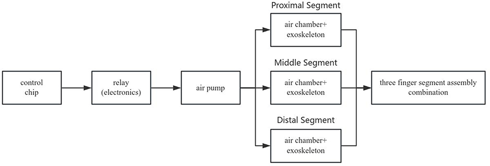 |
Figure 1 Structural Design Diagram of the Scheme. |
Structural Design
Structural Principle Design
To design soft actuators that align with the anatomical structure and movement patterns of the human finger, it is essential to determine the external morphology of the actuator from a biomimetic perspective.23 As shown in Figure 2, human finger joints include the metacarpophalangeal joint, proximal interphalangeal joint, and distal interphalangeal joint. The metacarpophalangeal joint is a biaxial joint capable of flexion, extension, abduction, and adduction movements, while the remaining joints are uniaxial and only permit flexion and extension. Achieving the objectives of finger rehabilitation training requires more than solely relying on flexion exercises to facilitate recovery. Therefore, it is necessary to design a soft exoskeleton finger actuator structure with segmental control capability.
 |
Figure 2 Diagram of the proximal phalanx. |
Based on the principles of morphology and functional bionics, this study has designed a multi-segment exoskeletal reconfigurable soft actuator that closely conforms to the human finger, as illustrated in Figure 3. By inflating air s through orifices, the system utilizes cavity expansion to generate bending or stretching motions. Mimicking human tendons, the design employs a series-connected multi-cavity configuration where independent air cavities inflate to achieve finger joint flexion. The actuator achieves active bending and recovery functions under pneumatic pressure, facilitating finger rehabilitation training by enabling controlled flexion and extension movements for patients.
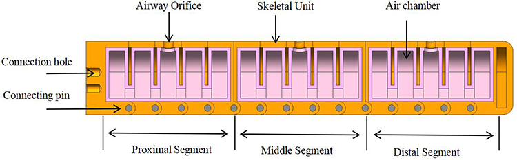 |
Figure 3 Cross-sectional diagram of the soft exoskeleton finger actuator. |
As shown in Figure 4, three independent finger segments were designed, each featuring air ducts and flexible air cavities. The dimensions of these air cavities were precisely matched with the skeletal structure to ensure seamless integration between the air cavities and the exoskeleton. The entire exoskeletal unit is assembled using connection pins, secured via pre-reserved mounting holes at the distal end. This configuration guarantees non-interfering movement between individual bones, enabling rotational and bending motions of the exoskeleton unit.
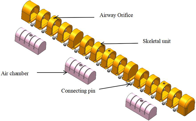 |
Figure 4 Exploded view of the soft exoskeleton finger actuator. |
Determination of Structural Parameters
Taking the middle finger as an example, its proximal phalanx length ranges from 44 to 51 mm, the middle phalanx from 25 to 31 mm, and the distal phalanx from 24 to 27 mm.23 Subsequently, by evaluating the influence of various geometric parameters within the aerodynamic network structure on the bending performance, specific parameter values were determined. The actuator length L is set to 130 mm, the width S to 19 mm, and the height H to 22.5 mm. Relevant dimensional parameters are detailed in Figures 5, 6 and Table 1.
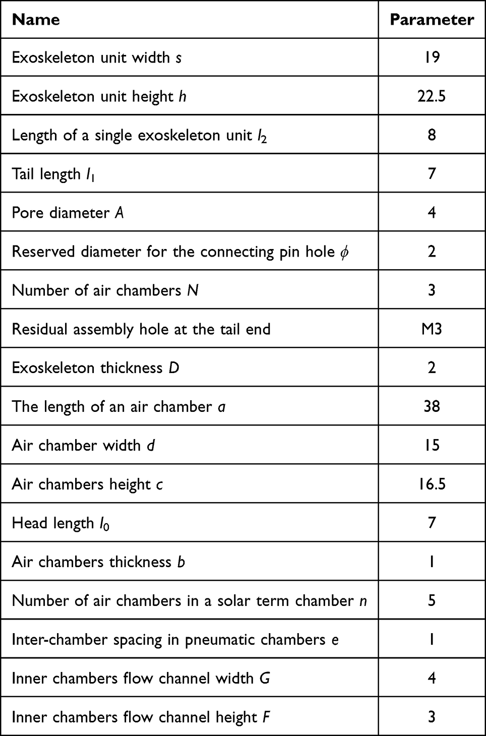 |
Table 1 Dimensional Data of the Soft Exoskeleton Finger Actuator (Units: Mm) |
 |
Figure 5 Cross-sectional dimensions of the soft exoskeleton finger actuator. |
 |
Figure 6 Cross-sectional dimensions of the soft robotic finger actuator for the exoskeleton. |
A Design Plan for a Finger Structure
As shown in Figure 7, this study innovatively constructed a segmental exoskeleton composed of five skeletal units (1). An arched air cavity (4) was integrated into the exoskeleton, with its dimensions precisely matched to the internal space. The air cavity was securely bonded to the exoskeleton using high-strength adhesive, ensuring seamless integration. Finally, connecting pins (3) are employed to link the entire series of exoskeletal units, ensuring independent motion between each segment while enabling smooth axial rotation for bending movements.
 |
Figure 7 The combination of the entire skeleton and the air cavity. (a) Assembly diagram of five exoskeleton units. (b) Display diagram of soft air cavity. (c) Display diagram of exoskeleton and air cavity after assembly. |
As illustrated in Figure 8, the components are described as follows:
 |
Figure 8 Cross-sectional analysis of the complete skeletal assembly. |
Component 1: Skeletal Unit: The standard skeletal unit features a dual-sided open configuration.
Component 2: Air Inlet Holes: Each segment contains centrally positioned air inlet holes for tracheal installation and air flow control.
Component 3: Connecting Pins: These pins interconnect each external skeletal unit.
As illustrated in Figure 9, the components are described as follows:
 |
Figure 9 Cross-sectional analysis of the combined cavity structure of the air cavity. |
Component 1: Air cavity body: arch-shaped air cavity, which is closely attached to the exoskeleton.
Component 2: Air Flow Channels: These channels link individual small cavities to ensure efficient air circulation.
Production and Assembly of Soft Rehabilitation Fingers
The multi-segment exoskeleton reconfigurable pneumatic soft robotic gripper features a complex structure, utilizing a modular manufacturing and assembly approach, with individual components fabricated separately and assembled uniformly. The air cavity of the actuator is made from silicone rubber, produced through mold injection molding, as illustrated in Figure 10. First, Inject AB glue (base A and curing agent B) is blended in the correct proportion, and after vacuum degassing to remove air bubbles, the liquid silicone is injected into moulds 1 and 2. Once cured, the moldings are demolded to form the air cavity section and the baseplate section. These two parts are then bonded together to complete the fabrication of the actuator’s air cavity.
 |
Figure 10 Manufacturing Process of Silicone Rubber Air Cavity. |
Figure 11 illustrates the detailed fabrication of the remaining components of the soft robotic gripper and the overall assembly process.
- Using 3D printing technology, various molds for exoskeletal units, central connecting palms, and air cavities are fabricated according to precisely designed dimensions.
- First, assemble the finger exoskeleton by sequentially connecting each unit with a cylindrical pin. The anterior and posterior ends of each segment of the skeletal unit are sealed with front and back closure bones to prevent external expansion of the exoskeleton during pneumatic inflation, as shown in Figure 11a. Once each skeletal unit is assembled, the hollow position of the embedded outer skeleton within the air cavity forms a finger joint segment, as shown in Figure 11b.
- Subsequently, the three segments of silicone air cavities are sequentially inserted into the corresponding sections of the exoskeleton, with anterior and posterior sealing bones employed to isolate each phalangeal segment. The cross-sectional view after embedding is shown in Figure 11c.
- Three silicone air tubes are sequentially inserted into the tracheal mounting holes located between the finger segment external skeletal units to independently control each finger segment. The mounting holes are carefully sealed with a high-strength adhesive to ensure the operational independence of each segment. The three-section exoskeleton and pneumatic cavity embedding profile diagram is shown in Figure 11d.
- The trachea must be reserved with sufficient length to accommodate axial extension following deformation of finger bending, with the complete finger morphology as shown in Figure 11e.
- According to the design concept, the pre-allocated sensor into the cross-section of the finger pad at the bottom end, as shown in Figure 11f.
 |
Figure 11 Manufacturing and assembly process of a four-finger soft robotic gripper. (a) Schematic diagram of the single-segment skeletal unit structure. (b) Schematic diagram of the structure where the air cavity is embedded in the hollow interior of the exoskeleton. (c) Cross-sectional view of the exoskeleton after the air cavity is embedded. (d) Overall schematic diagram of the three-segment exoskeleton unit and the embedded air cavity. (e) Outline structural diagram of the complete finger. (f) Installation schematic diagram of the sensor embedded in the bottom end face of the finger. |
Mathematical Modeling
Basic Conditions for Mathematical Modeling
Currently, due to the absence of a universal theoretical model, it is necessary to develop independent models tailored to soft finger actuators with different structures. The modeling process requires the formulation of appropriate conditional assumptions and simplifications. Therefore, to develop a mathematical model tailored to the structural design presented in this paper, it is essential to integrate the structural design principles outlined herein and select an appropriate mathematical modeling approach.
This multi-segment soft exoskeleton reconfigurable finger actuator is a nonlinear, large-deformation, multi-material, and pneumatically coupled system, involving numerous factors. The analysis indicates that this robotic finger can be modeled as a series of n interconnected finger joints, each with identical structural configurations and operating principles. Therefore, analysis can be performed on individual finger joints. To simplify the model, we make the following assumptions based on the actual operating environment and conditions of the system: short charging and discharging times are considered adiabatic processes, and only steady-state air pressure is taken into account. Therefore, the thermodynamic process is regarded as quasi-static while also satisfying the ideal air law. Silicone rubber exhibits no hysteresis effect; the rigid skeleton constrains its radial deformation, which is minimal and can be considered negligible. Additionally, internal and external leakage between air cavities and hinge clearances are disregarded.
Hyperelastic Body Strain Energy Function Model
This solution’s soft material is silicone rubber, which is incompressible and exhibits nonlinear large deformation behavior. Due to the Yeoh model’s advantages of a broad describable deformation range, fewer parameters, and the ability to be calibrated through stretch data, this study employs the Yeoh model to analyze the deformation behavior of silicone rubber. The strain energy function expressed in terms of the deformation tensor in the Yeoh model is:24
Based on the incompressibility of the material, the following relationship can be derived:

The strain energy density function of hyperelastic materials is:25

In the formula, C10 and C20 are dimensionless correlation constants determined through tensile testing of the material.8
The partial derivative of the main elongation ratio yields the relationship between stress and strain, expressed as:
The relationship between the principal axial force (ti) and the principal elongation ratio (λi) can thus be derived:


By integrating the formula and the binomial parameter form, it can be derived that:

Using  as the horizontal axis and
  as the vertical axis, the parameters of the Yeoh model were determined based on uniaxial tensile tests: C10 was set to 0.11 and C20 to 0.02.8
Single-Joint Bending Theory Model
Soft actuators achieve motion through the deformation of the material itself, which necessitates the establishment of a corresponding mechanical model. An exploration of domestic and international literature reveals that the assumption based on piecewise constant curvature is applicable to the modeling analysis of this research.
The segmented constant curvature assumption considers the entire soft actuator as composed of multiple identical joints, each modeled as an arc with a radius of curvature R. The overall bending deformation of the pneumatic soft actuator is regarded as the superposition of the bending angles of all the individual small cavities. As shown in Figure 12, the arc radius of each small air cavity is designated as L, the central angle as α, the chord length as K, and the radius of curvature as:26

 |
Figure 12 Deformation diagram of a single small air cavity. |
Since each small air cavity has an identical structure, the bending angle of each small air cavity is denoted as α.
By employing the piecewise constant curvature assumption method, the bending analysis of the soft actuator can be transformed into a study of a single air cavity. Since the input air pressure is identical for each air champer, the deformation of each air champer is also uniform. Therefore, to simplify the model, this study selects a single airbag for the analysis of its bending characteristics.
Virtual Work Principle
Based on the principle of virtual work, a system attains its minimum total potential energy at equilibrium. In this paper, the strain energy within the actuator is regarded as the total potential energy P. At equilibrium, the work performed by the pneumatic pressure is fully converted into the strain energy of the actuator.
The balanced equation is:27

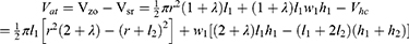
P represents the input air pressure, Vat denotes the deformed volume of the air cavity, and Vsr indicates the deformed volume of the silicone rubber material. Due to the incompressibility of silicone rubber, the volumes of Vsr and Vbt are identical, while Vbt represents the volume of the silicone material before deformation:

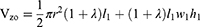
The deformed air cavity volume Vat = Vzo − Vsr, which Vzo represents the total volume of the balloon material and air cavity after deformation, Vsr has been determined from the above equation and Vzo can be derived based on the primary elongation ratio along the longitudinal axis of a single air champer:
Longitudinal primary strain ratio:

By combining the above equations and differentiating with respect to α, we obtain:


From the above formula, r, l, h, w, c, d, C10, and C20 are known quantities. Let α be the independent variable and P the dependent variable, resulting in a univariate function:

To obtain the bending Angle of a single small air cavity when pressure is added. The atmosphere cavity in this article is composed of 5 small air cavity, and the entire finger is composed of 3 atmosphere cavities. The bending angle of atmospheric cavity 1 is denoted as α1, atmospheric cavity 2 as α2, and atmospheric cavity 3 as α3. The total bending angle of the soft robotic finger is the sum of the three cavities’ angles: atmospheric cavity 1 + atmospheric cavity 2 + atmospheric cavity 3. Let the bending angle of each small air cavity be αij, where i represents the cavity number (1, 2, or 3), and j indicates the specific small air cavity within each main small air cavity. The overall bending angle of the soft robotic finger is αall, which can be expressed as:
Under the condition of uniform air cavity pressure, the total bending angle:

The relationship curve between the bending angle of the pneumatic soft actuator and the air pressure is illustrated in Figure 13.
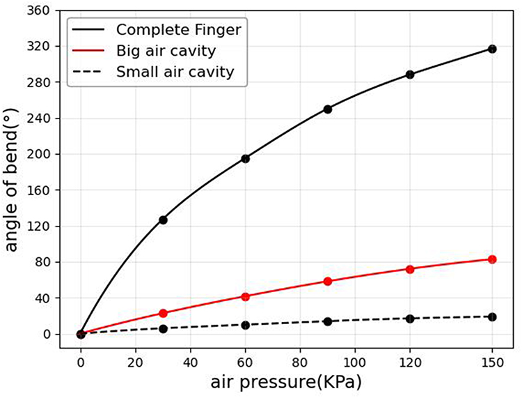 |
Figure 13 Curve illustrating the relationship between bending angle and air pressure. |
As shown in Figure 13, at the same air pressure, the bending angle of the finger is approximately three times that of a single big air cavity, while the bending angle of a single big air cavity is about five times that of a small air cavity.
Finger Kinematic Modeling
For any big air cavity of the soft robotic finger, since each atmospheric cavity is completely independent, they can be modeled as a small-scale series continuous system, with each hinge axis corresponding to a rotational joint within this system. Using the D-H method, the kinematic modeling of the soft actuator is performed, with each big air cavity containing five small air cavities. To map the joint space to the Cartesian coordinate system, a fixed reference frame is established at the end face, and a dynamic reference frame is set up at the rotating joints. The goal is to determine the pose coordinates of each component relative to the fixed coordinate system.
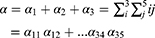
As shown in Figure 14, a fixed reference frame xoy is established with the o-axis as the origin. The coordinate systems of each small air cavity are constructed using the Denavit-Hartenberg (D-H) parameter method. Assuming the bending angle of the first big air cavity is zd1, and the bending angles of the individual sub-cavities within this big air cavity are i (i=1,2,3,4,5), the overall bending angle of the big air cavity can be determined using the following formula:28

 |
Figure 14 Kinematic modeling of the single-section D-H method for the big air cavity. |
The homogeneous transformation matrix between the coordinate systems of two adjacent big air cavities can thus be derived:

A homogeneous transformation matrix can be derived for any big air cavity coordinate system relative to a fixed reference frame through a series of coordinate transformations:
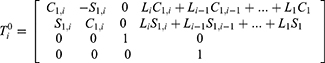

 ,
, Li represents the length of the i-th connecting rod.
Similarly, by analyzing the entire soft finger and establishing a base coordinate system at the center of the pneumatic soft actuator, a Denavit-Hartenberg (D-H) kinematic model can be constructed. This allows for the calculation of the transformation matrices of each small air cavity within the three main pneumatic cavities relative to the palm coordinate system. Given the known bending angles of each phalangeal joint in the pneumatic soft robotic finger, the position of the fingertip relative to the base coordinate system can be determined. This constitutes the kinematic mapping from joint space to Cartesian coordinates. The five small cavities within the main big air cavity exert identical pressure effects, allowing the derivation of a functional relationship between the bending angles of the five small cavities within the same big air cavity. Building on this, given the position of each small air cavity in the reference coordinate system, inverse kinematics can be applied to determine the bending angles of each finger joint.
Simulation Analysis
Simulation of Each Structure
The soft part of the physical object is made of LSR silicone material, and the multi-segment exoskeleton part is made of TPU plastic material. The geometric parameters are based on the previous description. The physical model is created using Unigraphics NX, and the relevant coefficients between the exoskeleton and the silicone cavity are big air cavity, small air cavity with exoskeleton, big air cavity with exoskeleton, and the entire finger segment regarding bending ability and driving force are conducted at 150 kPa.
In the simulation figure, U is the mode value, which is the combined mode value of three components. In this paper, the bending Angle data is measured according to the expansion effect of the simulation figure, and the driving force data is derived through simulation.
When the big air cavity is injected with an air pressure ranging from 0 to 150 kPa, the corresponding bending effect can be obtained as shown in Figure 15. Within the pressure range of 0 to 150 kPa, due to the pure soft structure of the big air cavity, the stress cloud map shows that the high-stress areas are dispersed on the side walls, and the radial expansion without constraints is significant. At 150 kPa, the expansion angle of the big air cavity is 93.34°.
 |
Figure 15 Simulation analysis of the expansion of the big air cavity under an air pressure of 0–150 kPa. (a) Initial state reference model without air pressure injection. (b) Deformation cloud diagram after 30 kPa air pressure injection. (c) Deformation cloud diagram after 60 kPa air pressure injection. (d) Deformation cloud diagram after 90 kPa air pressure injection. (e) Deformation cloud diagram after 120 kPa air pressure injection. (f) Deformation cloud diagram after 150 kPa air pressure injection. |
When the big air cavity without an exoskeleton is injected with 0–150 kPa pressure, the corresponding thrust effect diagram can be obtained as shown in Figure 16. Within the pressure range of 0 to 150 kPa, due to the pure soft structure of the big air cavity, the stress concentration on the side walls causes local buckling, and the change range of the driving force is not significant. At 150 kPa, the driving force of the big air cavity without an exoskeleton is 2.25 N.
 |
Figure 16 Simulation analysis of thrust for the big air cavity under an air pressure of 0–150 kPa. |
Injecting an air pressure ranging from 0 to 150 kPa into a small air cavity with an exoskeleton can yield the corresponding bending effect as shown in Figure 17. Within the range of 0 to 150 kPa, the small air cavity is radially expanded under the constraint of the exoskeleton, and the deformation is more controllable. At 150 kPa, the expansion angle of the small air cavity with exoskeleton is 21.13°.
 |
Figure 17 Simulation analysis of the expansion of the small air cavity with exoskeleton under an air pressure of 0–150 kPa. (a) Initial state reference model without air pressure injection. (b) Deformation cloud diagram after 30 kPa air pressure injection. (c) Deformation cloud diagram after 60 kPa air pressure injection. (d) Deformation cloud diagram after 90 kPa air pressure injection. (e) Deformation cloud diagram after 120 kPa air pressure injection. (f) Deformation cloud diagram after 150 kPa air pressure injection. |
Injecting 0–150 kPa air pressure into a small air cavity with an exoskeleton can yield the corresponding thrust effect diagram as shown in Figure 18. Within the pressure range of 0 to 150 kPa, the small air cavity is radially expanded under the constraint of the exoskeleton, and the stress is concentrated in the contact area of the end face, with the expansion force concentrated at the end face output. At 150 kPa, the expansion force of the small air cavity with exoskeleton is 1.2 N.
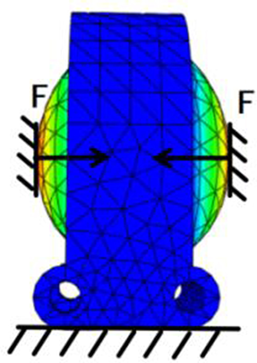 |
Figure 18 Simulation analysis of thrust of the small air cavity with exoskeleton under an air pressure of 0–150 kPa. |
Injecting an air pressure of 0–150 kPa into the big air cavity with the exoskeleton can yield the corresponding bending effect as shown in Figure 19. Within the pressure range of 0 to 150 kPa, compared to the big air cavity without exoskeleton, the exoskeleton suppresses the ineffective deformation, reduces the radial deformation energy, while making the bending angle larger. Taking 150 kPa as an example, the bending angle of the big air cavity with exoskeleton is 105.08°, compared to the bending angle of 93.24° of the big air cavity without exoskeleton, the bending angle has increased by 12.6%.
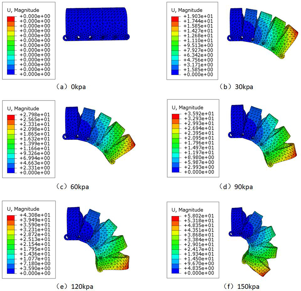 |
Figure 19 Simulation analysis of the expansion of the big air cavity with exoskeleton under an air pressure of 0–150 kPa. (a) Initial state reference model without air pressure injection. (b) Deformation cloud diagram after 30 kPa air pressure injection. (c) Deformation cloud diagram after 60 kPa air pressure injection. (d) Deformation cloud diagram after 90 kPa air pressure injection. (e) Deformation cloud diagram after 120 kPa air pressure injection. (f) Deformation cloud diagram after 150 kPa air pressure injection. |
At the same time, the bending angle of the big air cavity with exoskeleton is close to the expansion angle of the 5 small air cavities with exoskeleton (105.65°), with an error of 0.54%, proving that the mathematical model and the simulation are highly consistent.
Injecting 0–150 kPa big air pressure into the big air cavity with exoskeleton can yield the corresponding thrust effect as shown in Figure 20. Within the pressure range of 0 to 150 kPa, compared to the big air cavity, the area where the end face stress concentrates expands, and its driving force is also greater. At 150 kPa, the big air cavity with exoskeleton is 6.46 N. It can be seen that compared with the 2.25 N driving force of the air cavity without an external skeleton, the design with an external skeleton increases the driving force of the actuator by 187%.
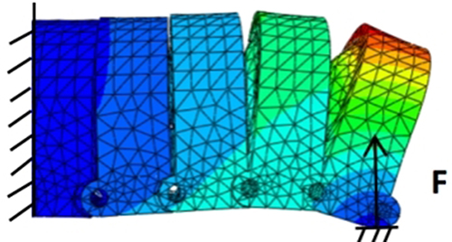 |
Figure 20 Simulation analysis of thrust of big air cavity with exoskeleton under an air pressure of 0–150 kPa. |
When 0–150 kPa air pressure is injected into the entire finger segment, the corresponding bending effect can be obtained as shown in Figure 21. Within the pressure range of 0 to 150 kPa, the small air cavity structure disperses local stress, making the bending process more in line with human movement. At the same time, the bending angle covers the entire range of human hand movement. At 150 kPa, the expansion angle of the entire finger segment is 319.41°, which is close to the expansion angle of the three big air cavities with exoskeleton (315.24°), with an error of 1.3%, proving that the mathematical model and the simulation are highly consistent.
 |
Figure 21 Simulation analysis of expansion of the entire finger under an air pressure of 0–150 kPa. (a) Initial state reference model without air pressure injection. (b) Deformation cloud diagram after 30 kPa air pressure injection. (c) Deformation cloud diagram after 60 kPa air pressure injection. (d) Deformation cloud diagram after 90 kPa air pressure injection. (e) Deformation cloud diagram after 120 kPa air pressure injection. (f) Deformation cloud diagram after 150 kPa air pressure injection. |
When injecting 0–150 kPa air pressure into the entire finger, the corresponding thrust effect can be obtained as shown in Figure 22. Within the pressure range of 0 to 150 kPa, the deformation trajectory is a smooth and continuous arc, without local distortion. This proves that the distributed small air cavity design results in lower local strain energy density and lower attenuation of the external skeleton’s transmission of strain energy. There is a stress buffer zone between adjacent air cavities, and the end face stress is uniformly distributed without edge concentration. This fundamentally inhibits irregular deformation. At 150 kPa, the driving force of the entire finger segment is 11.24 N.
 |
Figure 22 Simulation analysis of the thrust of the entire finger under an air pressure of 0–150 kPa. |
From Figures 16, 18, 20 and 22, it can be seen that each big air cavity can be regarded as an independent series system of the entire finger segment, and the small air cavity is a series system of the big air cavity. This proves that by independently adjusting the air pressure of each big air cavity, the independent deformation and movement of the finger segment unit can be achieved; based on this segmented, precise control, the system can complete the specific overall form reconstruction.
From Figure 22, under the condition that the maximum air pressure that the actual air pump can output is approximately 150 kPa, the driving force generated by the multi-segment external skeleton reconfigurable soft body finger actuator in the simulation is 11.24 N. It is 1.74 times that of a single external skeleton air cavity, proving that the external skeleton can efficiently convert radial deformation into axial output through constraint, and the increase in driving force is not a simple linear superposition, but through strain energy coupling and redistribution. This simulation result verifies the theoretical feasibility of the design in this paper and estimates its performance under the working air pressure. This provides an important theoretical basis and performance expectations for the subsequent manufacturing and experimental testing of the physical prototype.
To further explore the relationship between air pressure, the bending angles of each structure, and the driving force, data analysis based on the line graph was conducted for the small air cavity with the external skeleton, the big air cavity, the big air cavity with exoskeleton, and the entire finger segment under different air pressure conditions, and the results are shown in Figures 23 and 24.
 |
Figure 23 Simulation line graph of bending angles for each structure. |
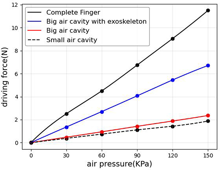 |
Figure 24 Simulated line graphs of each structural driving force. |
As shown in Figure 23, the trend of the bending angle changes with the air pressure conforms to the typical laws of linear low-pressure and saturated pneumatic bending under high pressure. This proves that through the distributed layout designed in this paper, the deformation degree of each part of the bending is uniform, thereby enhancing the overall ability to resist irregular deformation.
From Figures 23 and 24, it can be seen that the bending angle is significantly positively correlated with the driving force. Higher driving force stems from greater internal stress, which in turn leads to a higher bending angle. By comparing the simulated line graphs of the big air cavity and the one with exoskeleton in terms of the bending angle and driving force, it can be observed that the exoskeleton design constrains the radial deformation of the big air cavity, converting the radial deformation energy into the bending angle and driving force. This design enhances the bending angle while also increasing the driving force. Thus, the design in this paper has better rehabilitation capabilities.
Simulation of Segmented Control Capability
To verify the segmented control capability of the multi-segment exoskeleton reconfigurable soft tissue finger actuator, 150 kPa of air pressure was applied to the proximal segment, middle segment, and distal segment of the entire finger in different combinations to test the independent control capability of each segment of the actuator.
From Figures 25–31, it can be seen that the multi-segment exoskeleton reconfigurable soft finger actuator designed in this paper has a motion process that conforms to the movement characteristics of human fingers. This proves that its segmented, reconfigurable structure is suitable for the normal range of finger activities. The simulation results show that there are differences in the output of each segment, and the overall output is predictable This indicates that this design not only allows segmented independent control but also expresses reconfigurability in the overall operation.
 |
Figure 25 Simulation diagram of the motion of the distal segment under an air pressure of 150 kPa. |
 |
Figure 26 Simulation diagram of the motion of the middle segment under an air pressure of 150 kPa. |
 |
Figure 27 Simulation diagram of the motion of the proximal segment under an air pressure of 150 kPa. |
 |
Figure 28 Simulation diagram of the motion of the proximal segment and middle segment under an air pressure of 150 kPa. |
 |
Figure 29 Simulation diagram of the motion of the proximal segment and distal segment under an air pressure of 150 kPa. |
 |
Figure 30 Simulation diagram of the motion of the middle segment and distal segment under an air pressure of 150 kPa. |
 |
Figure 31 Simulation diagram of the motion of the proximal segment, middle segment, and distal segment under an air pressure of 150 kPa. |
To further verify the reconfigurability of the multi-segment exoskeleton reconfigurable soft finger actuator designed in this paper, taking the proximal finger segment injecting 60 kPa air pressure, the middle finger segment injecting 30 kPa air pressure, and the distal finger segment injecting 60 kPa air pressure as an example, as shown in Figure 32.
 |
Figure 32 Simulation diagram of motion reconstruction with different air pressures injected into the air cavity. |
Using the upper-left corner of the proximal finger segment’s cross-section as the origin coordinate system with X-axis orientation to the right and Y-axis orientation downward, we applied mathematical formulas (17), (22), and (23) to determine the terminal positions of six finger segments at 60 kPa, 30 kPa, and 60kPa respectively. The coordinates for points A (30.51, 42.36), B (23.72, 75.92), and C (−9.84, 96.11) were obtained. As shown in Figure 32, the simulation results show coordinates for points A (30.25, 42.44), B (23.89, 75.69), and C (−9.86, 95.96). The maximum error between the mathematical model and simulation results was 0.85%, demonstrating the effectiveness of the multi-segment coordinated kinematic model. Results derived from mathematical formulas under these conditions closely matched simulation outcomes, validating the reconfigurability of our design. This configuration ensures flexibility and adaptability, laying the foundation for diverse rehabilitation training tasks. For instance, during training, each finger segment can independently bend and apply force.
Physical Experiment
To verify the actual capabilities of the multi-segment exoskeleton reconfigurable soft finger actuator, this paper designs a physical experiment based on data analysis. The physical object in this paper is manufactured through processes such as mold design, air cavity casting, 3D printing of the exoskeleton, and overall assembly, with specific procedures referring to the structural design part above. The mechanical components consist of a rigid exoskeleton and a soft air cavity, each made from distinct materials. The exoskeleton is 3D-printed from Eryize PLA, characterized by a density of 1.24–1.27 g/cm3, tensile strength of 40–60 MPa, elastic modulus of 3–4 GPa, and elongation at break of 4%–7%. Conversely, the soft air cavity is poured from an AB adhesive system, and the cured material exhibits a Shore A hardness of 40, a tensile strength of 2–4 MPa, an elongation at break of 150%–250%, and an elastic modulus of 1–3 MPa.
The static mechanics experimental system designed in this paper is shown in Figure 33. This system collects data on the bending angle and driving force by installing bending sensors on the actuator and force gauges on the head. During the force measurement, to accurately obtain the driving force, the tail and middle sections of the finger and the force gauge were also fixed. The system utilizes a multi-sensor configuration to provide high-precision data for subsequent analysis. The pressure is monitored using a Qingze ISE30A-01-P-L pressure gauge with a range of −0.100 to 1.000 MPa and an accuracy of 0.001 MPa. The output force is measured by a Shunkeda SN-50 dynamometer, which has a range of 50 N, an accuracy of 0.01 N, and an error of less than ±1%. Finger joint flexion is tracked in real-time with a RunesKee BF350-3AA bending sensor, offering a range of 0° to 360°, an accuracy of 0.1°, and an error of ±1%.
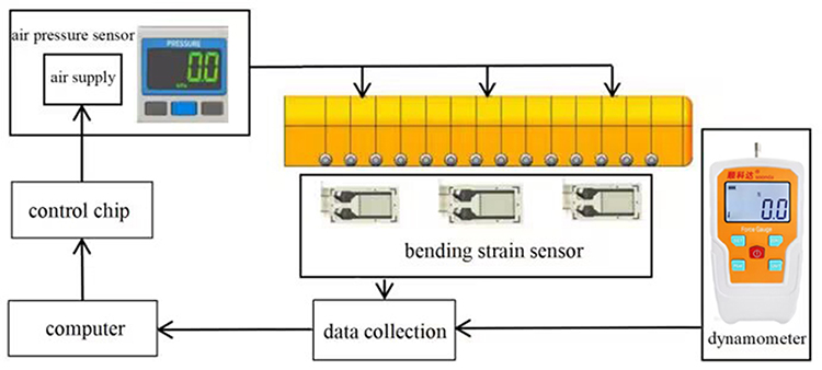 |
Figure 33 Static experiment system of the actuator. |
The system monitors the air source pressure through a pressure sensor, detects the structural bending strain through a bending strain sensor, measures the acting force through a dynamometer, and the data from both are transmitted to the computer through data collection for storage. At the same time, the computer controls the air source through the control chip.
To verify the segmental control capability, a segmented control method is adopted to apply air pressure to different structures. The bending angles and driving forces of the big air cavity, big air cavity with exoskeleton, and the entire finger under different air pressures are measured respectively through bending sensors. The experiments are shown in Figures 34 and 35.
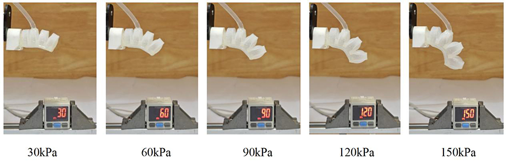 |
Figure 34 Expansion analysis of the big air cavity without exoskeleton injected with 0–150 kPa air pressure. |
 |
Figure 35 Thrust analysis of the big air cavity without exoskeleton injected with 0–150 kPa air pressure. |
It can be seen from Figure 34 that the bending angle of the big air cavity without an exoskeleton increases non-linearly with the increase of air pressure. The slope is larger in the low-pressure zone (0–90kPa), and the growth slows down in the high-pressure zone (120–150 kPa), indicating that the material deformation gradually saturates.
It can be seen from Figure 35 that the maximum driving force of the big air cavity without an exoskeleton is 2.36 N, which indicates that the energy conversion efficiency of the pure soft air cavity is low, and the deformation energy is wasted in radial expansion.
It can be seen from Figure 36 that the bending angle of the big air cavity with exoskeleton is still non-linear, but compared with the big air cavity without exoskeleton, its saturation trend is weakened, which proves that the exoskeleton inhibits invalid deformation. At the same time, under 150kPa, the bending angle of the big air cavity with exoskeleton (112.6°) is larger than that of the big air cavity without exoskeleton (100.1°), which proves that the radial deformation of the original big air cavity is converted into axial deformation due to the constraint of the exoskeleton, resulting in a larger bending angle.
 |
Figure 36 Expansion analysis of the big air cavity with exoskeleton injected with 0–150 kPa air pressure. |
It can be seen from Figure 37 that under the same air pressure, compared with the big air cavity without an exoskeleton, the exoskeleton restricts radial expansion, forcing the air pressure energy to be converted into driving force. Taking 150kPa as an example, the driving force of the big air cavity with exoskeleton is 6.71N, which is 184% higher than that of the big air cavity without exoskeleton (2.36 N). At the same time, compared with the 187% improvement in the simulation under the same conditions, the error is 1.6%, which verifies the authenticity of the above simulation.
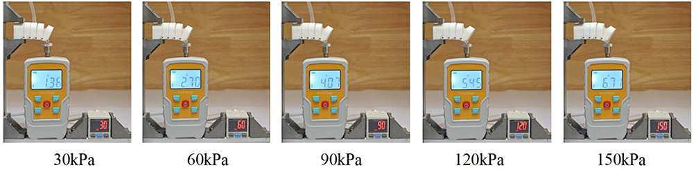 |
Figure 37 Thrust analysis of the big air cavity with exoskeleton injected with 0–150 kPa air pressure. |
It can be seen from Figure 38 that the bending angle of the entire finger is close to the sum of the angles of the 3 independent big air cavities. For example, under 150 kPa, the bending angle of the entire finger is 338.7°, and the sum of the bending angles of the 3 big air cavities with exoskeleton is 337.8°, with an error of only 0.2%, which verifies the authenticity of the above simulation and mathematical modeling analysis.
 |
Figure 38 Expansion analysis of the entire finger injected with 0–150 kPa air pressure. |
It can be seen from Figure 39 that the driving force attenuation of the entire finger in the high-pressure zone (90–150 kPa) is less than that of the unconstrained air cavity, which proves that the exoskeleton maintains stability under high pressure.
 |
Figure 39 Thrust analysis of the entire finger injected with 0–150 kPa air pressure. |
The above measurement results under 0~150 kPa are listed with 30 kPa as the division value, and the results are shown in Tables 2 and 3.
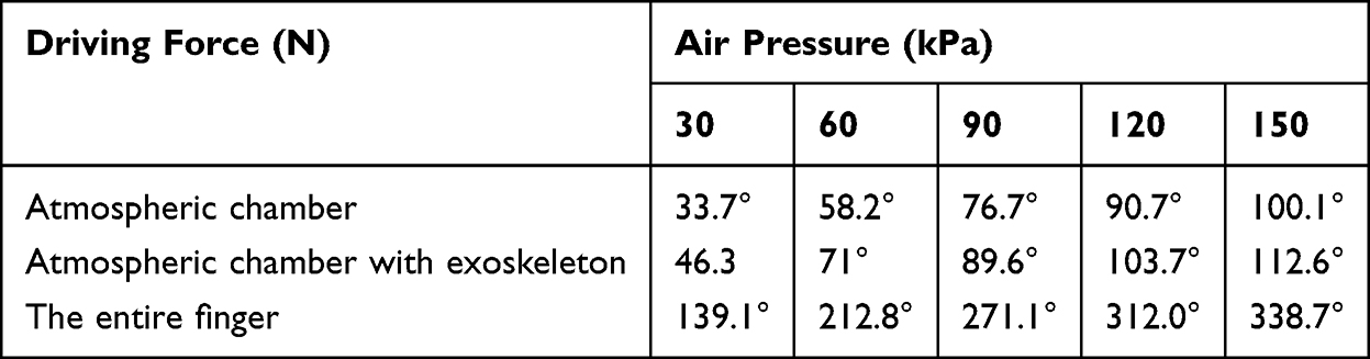 |
Table 2 Physical Test Data of Bending Angles Under Segmented Testing |
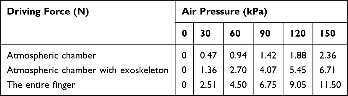 |
Table 3 Physical Test Data of Driving Forces Under Segmented Testing |
It can be seen from the data in Table 2 that, thanks to the segmented structural design, the big air cavity with exoskeleton is constrained by local stiffness due to physical isolation, and its bending angle is significantly larger than that of the big air cavity without exoskeleton under the same air pressure. Taking 150 kPa as an example, the bending angle of the big air cavity with exoskeleton is 112.6°, which is 12.4% higher than that of the big air cavity without exoskeleton (100.1°). At the same time, compared with the 12.6% improvement in the simulation under the same conditions, the error is 1.5%, which proves that the simulation and the physical object jointly verify the ability of the exoskeleton to constrain the radial deformation of the air cavity.
From the data in Table 3, based on Pearson correlation coefficient analysis, all test items show a very strong positive linear correlation (r > 0.99), confirming that the increase in driving force is highly linearly related to the increase in air pressure. The order of correlation strength is: The entire finger (r = 0.997) ≈ big air cavity with exoskeleton (r = 0.996) > big air cavity (r = 0.993). Among them, the linearity of the big air cavity with exoskeleton is greater than that of the big air cavity, indicating that adding an exoskeleton helps to improve the linear response characteristics of the system. Although the entire finger shows a very high linearity (r = 0.997), a slight attenuation trend in the driving force increase is observed in the high-pressure range (120–150 kPa), which may be caused by factors such as material or air pressure saturation effects; overall, a very strong linear relationship is still maintained. This result confirms that the flexible driving structure designed in this paper can prevent irregular deformation under the condition of no external load, effectively suppressing unexpected and irregular deformation.
In addition, the experiment observed that when multiple adjacent air cavities are activated at the same time, the exoskeleton restricts the radial expansion of the air cavities, forcing the deformation energy to be released along the axial direction. For example, under 150 kPa, the driving force of the entire finger (11.50 N) under multi-cavity cooperation is about 1.71 times that of the big air cavity with exoskeleton (6.71 N). This proves that the superposition effect is not a simple linear addition, but the coupled redistribution of strain energy under constraints, which is transmitted through the exoskeleton. At the same time, compared with 1.73 times in the simulation under the same conditions, the error is 1.7%, which proves that the simulation and the physical object jointly verify the non-linear mechanism of the driving force superposition effect.
To further verify the reconfigurability of the multi-segment exoskeleton reconfigurable soft finger actuator designed in this paper, take the example where the proximal finger segment is injected with 60 kPa air pressure, the middle finger segment with 30 kPa air pressure, and the distal finger segment with 60 kPa air pressure, as shown in Figure 40.
 |
Figure 40 Motion reconfiguration experiment diagram of air cavities injected with different air pressures. |
As shown in Figure 40, with the upper-left corner of the proximal phalangeal section’s cross-section as the origin coordinate system, the X-axis is oriented to the right and the Y-axis to the bottom. Experimental measurements obtained coordinates for points A (31.96, 43.65), B (22.60, 77.40), and C (−10.35, 94.80). Simulated coordinates showed A (30.25, 42.44), B (23.89, 75.69), and C (−9.86, 95.96). The actual motion patterns showed a maximum error of 5.71% between measured and simulated coordinates, validating both the formula’s reliability and simulation accuracy. This part of the error mainly stems from two aspects. In the simulation, the boundary conditions are assumed to be completely fixed, and the geometric structure is idealized, which leads to errors. In the experimental aspect, the errors mainly come from the processing errors of 3D printing technology, the manual errors during assembly, and the insufficient precision of the molds for the soft air cavities. To reduce these errors, future work can be improved in two aspects: in the simulation, more realistic boundary conditions can be introduced to simulate the actual gaps and flexibility; in the physical manufacturing, integrated printed flexible hinges can be adopted, and the key mating surfaces can be slightly trimmed, while the manufacturing precision of the molds can be enhanced.
To verify the accuracy of the mathematical model and simulation, the physical test results of the bending angle of the entire finger under 0 to 150 kPa air pressure were compared with the results of mathematical modeling and simulation to observe the error. The results are shown in Figure 41.
 |
Figure 41 Comparison of bending angle results between physical testing, simulation testing, and mathematical modeling. |
As shown in Figure 41, the mathematical model and simulation results exhibit a high degree of consistency, with a relative error of less than 1%, thereby validating the accuracy of the mathematical modeling. The physical experimental results closely align with the simulation predictions, demonstrating a relative error below 5%. To systematically evaluate experimental uncertainty, the error bars in the figure represent the standard error of the mean calculated from ten independent repeated measurements, reflecting the epistemic uncertainty arising from limited sampling. Statistical tests indicate that all simulated values fall within the 95% confidence interval of the experimental data, confirming no statistically significant difference between them. Further analysis reveals that the residual deviations primarily stem from parameter uncertainties introduced during the manufacturing process, specifically attributable to machining tolerances in 3D printing and molding. These factors were accounted for in the simulations, yet resulted in discrepancies between the simulated and measured values of bending angles. This experiment provides a basis for subsequent calibration of the mathematical model and precision requirements in physical manufacturing.
As illustrated in Figure 42, the physical experiments and simulation results demonstrate a high degree of consistency, with a relative error of less than 5%. To quantify the uncertainty in the experimental data, the error bars represent the standard error of the mean calculated from 10 independent repeated measurements. Statistical tests confirm that all simulated predictions fall within the 95% confidence interval of the experimental data, indicating no statistically significant difference between them. The residual errors can be attributed to two insufficiently characterized systematic factors: first, the simplified modeling of joint friction characteristics introduces model-form uncertainty, which fails to accurately capture the true nonlinear dynamic behavior; second, discrepancies between the idealized fixed boundary conditions and the physical system lead to boundary condition uncertainty, neglecting the effects of human soft tissue deformation and individual wear variations on motion transmission accuracy. This experiment, through the identification and analysis of the aforementioned error sources, provides a critical theoretical foundation and practical direction for subsequent model refinement and control strategy optimization.
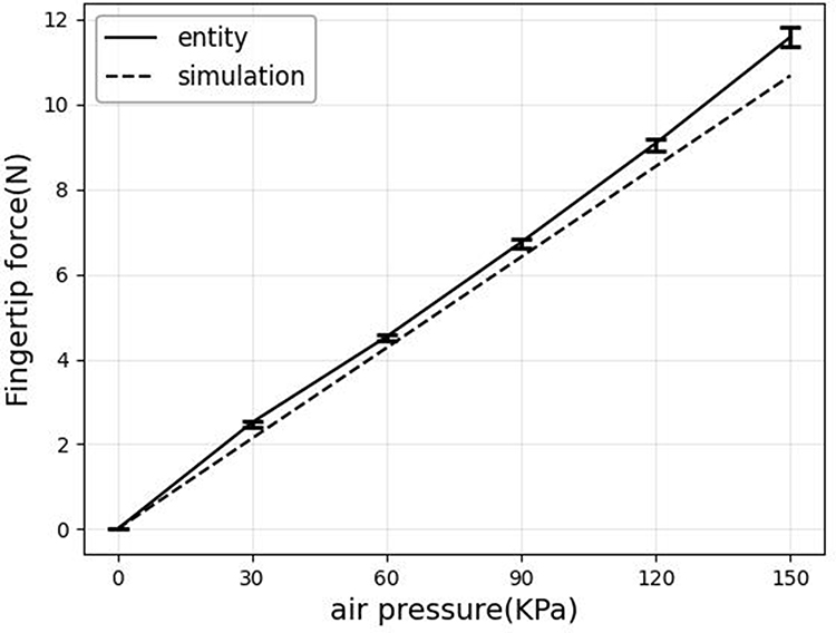 |
Figure 42 Comparison of driving force results between the physical test and simulation test. |
This study confirmed that the performance of the hand rehabilitation exoskeleton in terms of driving force and joint angle control meets the basic rehabilitation requirements, providing a technical basis for subsequent clinical applications. However, the current research is still in the principle verification stage, with an ideal experimental environment and without fully considering the uncertain factors in actual use. At the same time, the current research has not fully examined the impact of material fatigue and mechanical wear on system stability under long-term use. There is a lack of support from high-cycle fatigue tests. In terms of manufacturing cost, although the cost of the materials used is relatively low, the existing process relying on 3D printing and custom molds still leads to a relatively high overall cost. Additionally, the long-term clinical capability of the device has not been fully verified and needs to be evaluated through more systematic real-scenario trials.
In addition to the aforementioned technical challenges, this research holds significant implications for rehabilitation medicine. The quantifiable and adjustable characteristics demonstrated by this exoskeleton in motion control offer a potential precise training method for hand function rehabilitation. It is expected to drive rehabilitation training from empirical to precise, further enhancing rehabilitation efficiency and personalization, and providing a reference for the development of intelligent rehabilitation devices. In addition to the aforementioned technical challenges, this research holds significant implications for rehabilitation medicine. The quantifiable and adjustable characteristics demonstrated by this exoskeleton in motion control offer a potential precise training method for hand function rehabilitation. It is expected to drive rehabilitation training from empirical to precise, further enhancing rehabilitation efficiency and personalization, and providing a reference for the development of intelligent rehabilitation devices.
Conclusion
In this paper, a multi-segment exoskeleton reconfigurable soft finger actuator design is proposed and validated for the existing soft finger actuators, which are generally characterized by the problems of irregular deformation, insufficient driving force, lack of segmental control, and low rigidity of movement maintenance. The design effectively constrains the radial expansion through the multi-segment exoskeleton structure, improves the rigidity maintenance ability, solves the irregular deformation problem, and ensures the stability and precision of the movement; in terms of control, the segmental control of each finger segment is realized, which supports a variety of rehabilitation training tasks, and the positional data of each finger segment under different air pressures have an error of less than 5% from the simulation, which proves the reconfigurability in this paper; in terms of theory, the mathematical model of this paper has been simulated and validated. The mathematical model of this paper is fully verified by simulation, and the error with both simulation and real objects is less than 10%, which provides a solid theoretical foundation for the design; in terms of performance, the maximum bending angle of the actuator is 338.7°, and the maximum driving force of the actuator reaches 11.50 N, which is 25.27% higher than the maximum driving force of 9.18 N of the existing research; verified by finite element simulation After finite element simulation and hydrostatic experiment verification, This study demonstrates outstanding performance in terms of bending angle, driving force, and control precision. Its key future value lies in its clinical application potential, with subsequent research focusing on patient trials in real-world medical environments to comprehensively evaluate its rehabilitation efficacy. However, further exploration is needed regarding the challenges of practical clinical implementation. To enhance the clinical effectiveness of rehabilitation therapy, follow-up work will prioritize patient clinical trials and long-term follow-up studies, thoroughly validating its safety, efficacy, and human-robot interaction performance in authentic rehabilitation scenarios. The design presented in this study effectively addresses these critical issues, with core performance metrics fully meeting the fundamental requirements of hand rehabilitation training, thereby establishing a solid technical foundation for clinical translation. It provides a practical and feasible device solution for efficient and reliable hand functional rehabilitation training, demonstrating clear prospects for clinical application and translational value.
Data Sharing Statement
The data that support the findings of this study are available from the corresponding author upon reasonable request.
Funding
This research was supported by the basic ability improvement project of young and middle-aged teachers in Guangxi Universities (No.2025KY0677, Project Name: Design and Research of Multi segment Reconfigurable Soft Pneumatic Finger Rehabilitation Machinery).
Disclosure
The authors declare that they have no conflicts of interest in this work.
References
1. Li Y. Effects of Force Feedback Hand rehabilitation Robot Combined with Task-Oriented Training on Finger Thick Grip Function in Hemiplegic Stroke Patients. Jilin University; 2022. doi:10.27162/d.cnki.gjlin.2022.006694
2. Williams N, Carey M, Stiller K. Finger flexor tendon injuries repaired surgically followed by an early active motion program: a prospective cohort study of clinician- and patient-reported outcomes. J Hand Ther. 2025. doi:10.1016/j.jht.2024.12.011
3. Son C, Jeong S, Lee S, et al. Tunable adhesion of shape memory polymer dry adhesive soft robotic Gripper via Stiffness control. Robotics. 2023;12(2):59. doi:10.3390/robotics12020059
4. Yang L, Wang H, Tian A, et al. Dynamic characteristics of flexible actuators based on transmission line theory and drive dynamics are analyzed. J Central South Univ. 2024;55(12):4442–32.
5. Zhang Z, Calderon AD, Huang X, Wu G, Liang C. Design and driving performance study of soft actuators for hand rehabilitation training. Med Devices. 2024;17:237–260. doi:10.2147/MDER.S476464
6. Saldarriaga A, Velasquez GIE, Colorado AH. Soft hand exoskeletons for rehabilitation: approaches to design, manufacturing methods, and future prospects. Robotics. 2024;13(3):50. doi:10.3390/robotics13030050
7. Lourenço B, Neto V, Andrade DR. A concept design of an adaptive tendon driven mechanism for active soft hand orthosis†. Proceedings. 2020;64(1):21.
8. Li K, Bi X, Li L, Zhao Y. A wearable hand-functional rehabilitation device based on pneumatic software drivers. Mach Tool Hydraulic. 2022;50(23):30–34.
9. Chu K, Yang J, Feng K, et al. It mainly refers to the design, simulation and test of a soft manipulator. For Mach Woodw Equip. 2021;49(12):34–40. doi:10.13279/j.cnki.fmwe.2021.0159
10. Ma K, Gao S, Jiang Z, et al. Research on hand rehabilitation device based on 3D soft driver. J Mech Eng. 2022;58(23):88–97.
11. Hyatt PL, Buskohl RP, Harne LR, et al. Harnessing liquid crystal elastomers for locomotion and mechanical intelligence in a soft robot. Soft Rob. 2025;12:631–639. doi:10.1089/soro.2024.0137
12. Yu X, Mei D, Wang J, et al. A finger-inspired pneumatic network actuator based on rigid-flexible coupling structure for soft robotic grippers. Intell Serv Rob. 2024;17(4):833–846. doi:10.1007/s11370-024-00543-4
13. Liu C, Pan T, Sun Y, et al. A segmented pneumatic soft drive for rehabilitation training. J Zhejiang Univ. 2022;56(06):1127–1134.
14. Amin H, Assal SFM, Iwata H. A new hand rehabilitation system based on the cable-driven mechanism and dielectric elastomer actuator. Mech Sci. 2020;11(2):357–369. doi:10.5194/ms-11-357-2020
15. Chen M. Modeling Simulation and Experimental Study of Fiber Reinforced Modular Soft Robot. Suzhou University; 2020. doi:10.27351/d.cnki.gszhu.2020.000723
16. Tu D, Zhao H, Zhu Q, et al. A design of a flexible holder combining rigidity and flexibility. Mod Manuf Eng. 2023;(10):120–125. doi:10.16731/j.cnki.1671-3133.2023.10.017
17. Shota K, Tortós EPV, Wenwei Y. Development and evaluation of fiber reinforced modular soft actuators and an individualized soft rehabilitation glove. Rob Auton Syst. 2024;171.
18. Cappello L, Meyer JT, Galloway KC, et al. Assisting hand function after spinal cord injury with a fabric-based soft robotic glove. J Neuro Eng Rehabil. 2018;15(1):59. doi:10.1186/s12984-018-0391-x
19. Liu H, Meng X, Zhu Y. Study on output force characteristics of flexible finger tip connected by two joints. Mach Tools Hydraul. 2022;50(21):59–62.
20. Bi C. Soft Robot Design for Hand Function rehabilitation Training. Dalian University of Technology; 2021. doi:10.26991/d.cnki.gdllu.2021.000776
21. Polygerinos PW, Wang Z, Galloway KC, Wood RJ, Walsh CJ. Soft robotic glove for combined assistance and at-home rehabilitation. Rob Auton Syst. 2015;73:135–143. doi:10.1016/j.robot.2014.08.014
22. Ouyang Y. Rehabilitation Training System for Finger Movement Function Based on Rope Drive. Southeast China University; 2021. doi:10.27014/d.cnki.gdnau.2021.000394
23. Cao X. Design and Experiment of Fiber Reinforced Pneumatic Soft Rehabilitation Glove. Nanjing University of Posts and Telecommunications; 2021. doi:10.27251/d.cnki.gnjdc.2021.000900
24. Polygerinos P, Wang Z, Overvelde JTB, et al. Modeling of Soft Fiber-Reinforced Bending Actuators. IEEE Trans Rob. 2015;31(3):778–789. doi:10.1109/TRO.2015.2428504
25. Yeoh OH. Some forms of the strain energy function for rubber. Rubber Chem Technol. 1993;5(6):754–771. doi:10.5254/1.3538343
26. Webster III RJ, Jones BA. Design and kinematic modeling of constant curvature continuum robots: a review. Int J Rob Res. 2010;29(13):1661–1683. doi:10.1177/0278364910368147
27. Cook RD. Concepts and Applications of Finite Element Analysis. John Wiley & Sons; 2002.
28. Denavit J, Hartenberg RS. A kinematic notation for lower-pair mechanisms based on matrices. 1955.
 © 2026 The Author(s). This work is published and licensed by Dove Medical Press Limited. The
full terms of this license are available at https://www.dovepress.com/terms
and incorporate the Creative Commons Attribution
- Non Commercial (unported, 4.0) License.
By accessing the work you hereby accept the Terms. Non-commercial uses of the work are permitted
without any further permission from Dove Medical Press Limited, provided the work is properly
attributed. For permission for commercial use of this work, please see paragraphs 4.2 and 5 of our Terms.
© 2026 The Author(s). This work is published and licensed by Dove Medical Press Limited. The
full terms of this license are available at https://www.dovepress.com/terms
and incorporate the Creative Commons Attribution
- Non Commercial (unported, 4.0) License.
By accessing the work you hereby accept the Terms. Non-commercial uses of the work are permitted
without any further permission from Dove Medical Press Limited, provided the work is properly
attributed. For permission for commercial use of this work, please see paragraphs 4.2 and 5 of our Terms.