Back to Journals » Medical Devices: Evidence and Research » Volume 11
A new mini-navigation tool allows accurate component placement during anterior total hip arthroplasty
Authors Parvizi J, Benson JR ![]() , Muir JM
, Muir JM
Received 16 September 2017
Accepted for publication 27 January 2018
Published 22 March 2018 Volume 2018:11 Pages 95—104
DOI https://doi.org/10.2147/MDER.S151835
Checked for plagiarism Yes
Review by Single anonymous peer review
Peer reviewer comments 3
Editor who approved publication: Dr Scott Fraser
Javad Parvizi,1,2 Jessica R Benson,3 Jeffrey M Muir3
1Department of Orthopaedic Surgery, Thomas Jefferson University Hospital, College of Biomedical Science, Philadelphia, PA, USA; 2Orthopaedics, Rothman Institute, Philadelphia, PA, USA; 3Department of Clinical Research, Intellijoint Surgical, Waterloo, ON, Canada
Introduction: Computer-assisted navigation systems have been explored in total hip arthroplasty (THA) to improve component positioning. While these systems traditionally rely on anterior pelvic plane registration, variances in soft tissue thickness overlying anatomical landmarks can lead to registration error, and the supine coronal plane has instead been proposed. The purpose of this study was to evaluate the accuracy of a novel navigation tool, using registration of the anterior pelvic plane or supine coronal plane during simulated anterior THA.
Methods: Measurements regarding the acetabular component position, and changes in leg length and offset were recorded. Benchtop phantoms and target measurement values commonly seen in surgery were used for analysis. Measurements for anteversion and inclination, and changes in leg length and offset were recorded by the navigation tool and compared with the known target value of the simulation. Pearson’s r assessed the relationship between the measurements of the device and the known target values.
Results: The device accurately measured cup position and leg length measurements to within 1° and 1 mm of the known target values, respectively. Across all simulations, there was a strong, positive relationship between values obtained by the device and the known target values (r=0.99).
Conclusion: The preliminary findings of this study suggest that the novel navigation tool tested is a potentially viable tool to improve the accuracy of component placement during THA using the anterior approach.
Keywords: total hip arthroplasty, computer-assisted navigation, anterior approach, accuracy, anterior pelvic plane, supine coronal plane
Introduction
The direct anterior approach to total hip arthroplasty (THA) has been gaining popularity in recent years.1 The proposed benefits of this surgical approach include its ability for muscle-sparing and the potential to improve post-operative patient outcomes.2,3 Indeed, studies have demonstrated that patients undergoing THA using the direct anterior approach had a shorter length of hospital stay, reduced pain, and faster return to function compared with other surgical approaches.4–6 However, patient-related factors, including body mass index (BMI)7 and anatomical features such as a wide or horizontal iliac wing,8 as well as surgical factors such as incision size, location, and limited visibility9 may inhibit the surgeon’s ability to accurately place components during THA. As a result, there is a risk for component malpositioning, a complication that may result in accelerated wear,10,11 instability,12,13 metallosis,14,15 and an increased probability of readmission and revision surgery.16–18
An advantageous aspect of THA performed via the anterior approach is the supine positioning of the patient, making the approach amenable to the utilization of C-arm fluoroscopy. This visual aid may assist surgeons with correctly selecting and positioning the acetabular and femoral components intraoperatively; however, the fluoroscopy process disrupts the surgical workflow and requires surgeons and some surgical team members to wear heavy lead aprons throughout the procedure. The imaging equipment also has to be transported into the operating room (OR) during the surgery, causing a further delay and potentially exposing the patient to sources of infection.19,20 These factors, in addition to a substantial learning curve of 100 cases associated with utilization of C-arm fluoroscopy and anterior THA,21–23 suggest that this approach may not be suitable for low-volume surgeons and institutions. Also, despite the qualitative advantage, C-arm fluoroscopy is not able to provide specific, objective data to surgeons intraoperatively. As such, a procedural gap for accurate and quantitative intraoperative measurements may exist.24
The potential muscle-sparing benefits of the anterior approach are countered by decreased access to the joint itself. Computer-assisted navigation is available to surgeons to assist with component placement during THA and may address the joint access issues, but is also associated with several drawbacks, including large capital costs, the cumbersome nature of incorporating computer-assisted navigation in the OR, and increased surgical time.25–28 In addition, there are limitations associated with the use of the anterior pelvic plane (APP) during patient registration. The variability in soft tissue thickness overlaying the 3 anatomical landmarks required for registration, the bilateral anterior superior iliac spines (ASIS), and symphysis pubis, can lead to registration error that inevitably impacts cup position (anteversion and inclination).29,30 Additionally, pelvic tilt in the sagittal plane is dynamic, and changes in pelvic tilt from supine to standing can have a significant effect on the functional orientation of the acetabulum.31 Alternative suggestions in some reports recommend use of the supine coronal plane in place of the APP for registration, as the anteversion and inclination values measured in the coronal plane correlate well with the measurements obtained from standard AP pelvic radiographs;32 however, there is no consensus opinion among surgeons.
The objective of the present study was to evaluate the ability of a new mini-navigation tool to accurately quantify measurements for cup position and leg length in benchtop simulations of anterior THA. Measurements that referenced both the APP and the supine coronal plane were collected for analysis.
Methods
Study design
This study utilized benchtop validation, performed on 2 separate occasions. The first series conducted on the navigation device utilized APP registration. In the second series, supine coronal plane registration was used.
Intellijoint HIP® Anterior Workflow
A detailed explanation of the lateral application of the navigation device has been previously described.33–35 In brief, Intellijoint HIP (Intellijoint Surgical, Inc., Waterloo, ON, Canada) is a US Food and Drug Administration-cleared, 3D mini-optical navigation system for use in THA that integrates into standard surgical workflow with minimal disruption. The system contains a camera, a probe, and a tracker, all located within the sterile field. Using optical technology, infrared light, and integrated microelectronics, the system captures real-time data regarding cup position and relays it to a workstation, located outside of the sterile field but within view of the surgeon. The camera is magnetically attached to a pelvic platform that sits atop 2 surgical screws inserted into the ipsilateral iliac crest. The camera captures the movements and the position of the tracker, which can be magnetically attached to various objects (e.g., impactor and surgical probe) during surgery. The tracker can also be magnetically attached to a femoral platform fixed to the greater trochanter via a single screw. Data are displayed on the workstation monitor and are available to the surgeon in real-time for reference at any time throughout the surgery.
The anterior application of the navigation tool utilizes the same hardware as the lateral application, with slight modifications due to the difference in patient positioning (lateral decubitus versus supine). In lieu of attachment of the pelvic platform to the lateral aspect of the ipsilateral iliac crest as in the lateral application, in the anterior application, the screws supporting the pelvic platform are inserted into the anterior aspect of the iliac crest on either the ipsilateral or contralateral side according to the preference of the surgeon. As in the lateral application, a small femoral platform is subsequently attached to the greater trochanter (Figure 1). Registration requires the use of the tracker and probe to register the patient in either the APP or the supine coronal plane. When registering the APP, surgeons use the probe to mark the left and right ASIS and the symphysis pubis, with each location captured by the system camera. When registering the coronal plane, however, only the bilateral ASIS are probed and recorded. Following dislocation and acetabular reaming, the tracker can be positioned onto the impactor to provide real-time measurements of anteversion and inclination to assist with cup implantation. Once seated, trial reductions and final cup and leg length measurements can be measured and saved, accordingly.
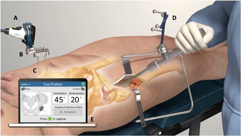 | Figure 1 Intraoperative utilization of the Intellijoint HIP® 3D mini-optical navigation tool (Intellijoint Surgical, Inc., Waterloo, ON, Canada). Notes: The camera (A) attaches magnetically to the pelvic platform (B). The platform is secured to the iliac crest of the patient’s pelvis via two pelvic screws (C). The device tracker (D) is magnetically fastened to the impactor. The camera is used intraoperatively to capture the positional changes of the tracker when registering the native orientation or while trialing the implant components. This positional information is then relayed to a workstation (E), located outside of the sterile field, for review by the surgeon. |
Benchtop validation testing
Two precision benchtop phantoms (Thorlabs, Newton, NJ, USA) were developed to provide accurate reference values for positional measurements regarding cup position (anteversion and inclination), leg length, and offset (Figures 2 and 3).
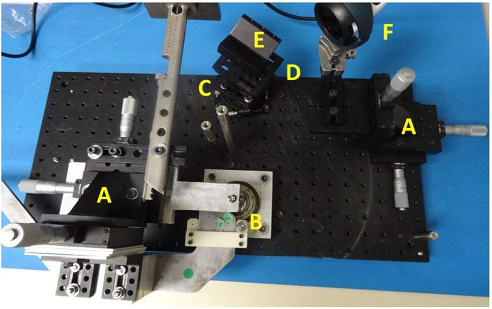 | Figure 2 The anterior benchtop phantom. Notes: The anterior benchtop platform was developed to simulate THA in the anterior approach. 25 mm XYZ translation stages (A; Part No.: PT3/M, Thorlabs Newton, NJ, USA) move the simulated femur and camera in the orthogonal directions of anterior-posterior, medial-lateral, and superior-inferior. The probe and tracker were used to capture leg length and offset measurements relative to a repeatable point (screw head) on the simulated greater trochanter (B). Discrete acetabular angles of inclination were created using a high-precision rotation mount (C; Part No.: PR01/M, Thorlabs). Discrete acetabular angles of anteversion were created using an adjustable angle mounting plate metric (D; Part No.: AP180/M, Thorlabs). Device measurements for anteversion and inclination were recorded by capturing the location of the tracker, attached to the impactor, in a repeatable location provided by the V-clamp (E; Part No.: VC3C/M, Thorlabs). Contralateral and ipsilateral measurements relative to the camera (F) were recorded for acetabular angles and femoral changes in leg length and offset. For simplicity, only ipsilateral acetabular measurements and contralateral femoral measurements are depicted. Abbreviation: THA, total hip arthroplasty. |
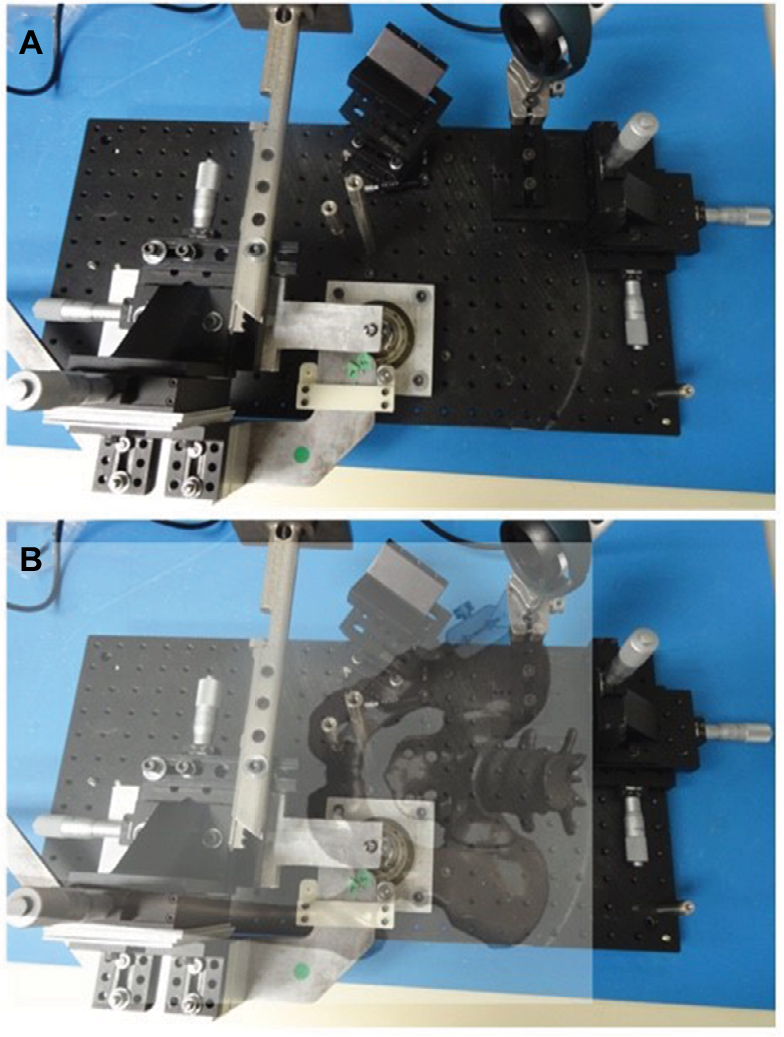 | Figure 3 Anterior benchtop phantom with pelvis and femoral overlay. Notes: The benchtop phantom representation of the pelvis (A), depicting a contralateral femur and ipsilateral acetabulum relative to the camera (B). |
To test acetabular cup position, the phantom used angular positioning stages and precision fixtures to mimic precise cup angles. Vertical and horizontal rotation stages were set at discrete angles that corresponded to impactor inclination and anteversion angles commonly observed during surgery. Specifically, reference anteversion target angles of 0°, 15°, and 30°, and reference inclination target angles of 15°, 30°, 45°, and 60° were used across 24 simulations. A calibrated electronic level confirmed angles prior to device testing. During device testing, a precision flat plate and v-clamp, mounted on the rotation stages, established the precise acetabular/implant and impactor planes, respectively (Figure 2). In each simulation, the probe function of the navigation tool was used to identify 3 screw heads, located on the precision flat plate in representation of the bilateral ASIS and pubis, to determine the acetabular reference plane; only 2 screws (the bilateral ASIS) were probed for supine coronal plane registration, whereas all 3 screws were probed for APP registration. The cup impactor with the device tracker attached was then inserted into the v-clamp to determine cup angle. Measurements were performed bilaterally to simulate likely cup positions encountered during surgery. Measurements obtained by the navigation tool were compared with the target values.
A separate phantom was used to simulate the pelvis and femur for leg length and offset measurements. Three precise micrometer positioning stages were mounted orthogonally to each other on each of the femoral and pelvic portions of the phantom and verified using calibrated dial indicators (Figure 2). Femoral positioning stages were used to generate leg length, offset, and anteroposterior distance changes. Reference target leg length and offset measurements included 0, 10, and 20 mm, with the phantom leg placed in the positions of neutral, 15° flexion, 15° abduction, and 15° external rotation. A total of 14 simulations were completed in each leg position. For the duration of testing, the camera was mounted on the pelvic portion of the phantom and the tracker was mounted on the femoral component. Three configurations were used throughout the simulations, representing small, medium, and large pelvis sizes.36,37
Statistical analysis
Statistical comparisons were made with alpha set a priori at 0.05. All mean values are presented as mean (95% CI or mean SD). Independent samples t-tests were used to compare APP and supine coronal measurements. Comparisons between device and true measurements were made using both Pearson’s r and the Bland–Altman technique.38,39 The Bland–Altman analysis provides a validated method for evaluating agreement between two methods of measurement. The Bland–Altman plot determines the bias between mean differences of 2 methods of measurement and generates a statistical limit agreement interval. A total of 95% of the difference of one method, when compared with the second method, falls within this statistical limit.40
Results
APP versus coronal plane
No significant difference was found between anteversion measurements obtained by APP registration versus the supine coronal plane (P=0.5). Similarly, no statistical significance was found between APP and supine coronal inclination differences (P=0.2).
APP benchtop validation
Anteversion
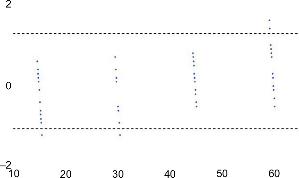
The mean absolute difference between measurements obtained by the navigation tool through use of the probe and the known target reference values of the phantom was 0.66° (SD: 0.37; range: 0.1°–1.45°). In turn, the mean absolute difference between anteversion measurements made by the system impactor and the associating known target values was 0.47° (SD: 0.19; range: 0.25°–1.0°). A strong positive relationship was observed between the reference target values and those obtained by the navigation system using the probe and impactor (r=0.99). These results are summarized in Table 1. Bland–Altman analysis demonstrated a strong agreement between measurements. A total of 94.4% (68/72) of paired anteversion measurements fell within the statistical limit of agreement (Figure 4).
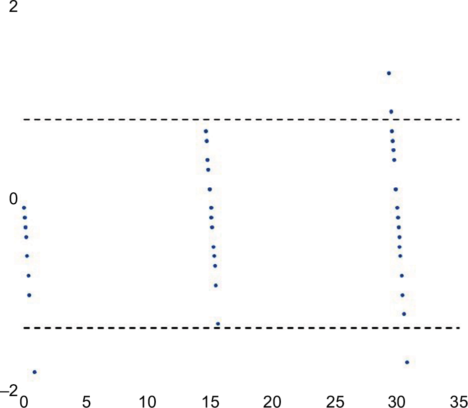 | Figure 4 Bland–Altman plot for APP anteversion. Notes: Bland–Altman analysis of APP anteversion showed excellent agreement between device measurements and true reference values. A total of 94.4% (68/72) of measurements fell within the statistical limit of agreement (dashed lines). Abbreviation: APP, anterior pelvic plane. |
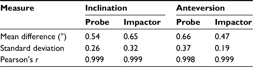 | Table 1 APP benchtop cup position summary of differences Abbreviation: APP, anterior pelvic plane. |
Inclination
The mean absolute difference between the known target inclination values and the measurements obtained by the device probe was 0.54° (SD: 0.26; range: 0.1°–1.0°), while the mean absolute difference between target inclination and inclination measurements made by the system impactor was 0.65° (SD: 0.32; range: 0.15°–1.25°). Similar to the results for anteversion, a strong positive relationship was observed between measurements obtained by the navigation tool and the reference target inclination values (r=0.99). These results are summarized in Table 1. Bland–Altman analysis also demonstrated a strong agreement between inclination measurements. A total of 94.4% (68/72) of paired inclination measurements fell within the statistical limit of agreement (Figure 5).
 | Figure 5 Bland–Altman plot for APP inclination. Notes: Bland–Altman analysis demonstrated a strong agreement between APP inclination measurements. A total of 94.4% (68/72) of inclination measurements fell within the statistical limit of agreement (dashed lines). Abbreviation: APP, anterior pelvic plane. |
Leg length and offset
The results for leg length and offset are summarized in Table 2. Mean absolute differences between device leg length measurements and reference measurements were 0.26 mm (SD: 0.26; range: 0.0–0.9 mm), 0.27 mm (SD: 0.21; range: 0.0–0.8 mm), 0.15 mm (SD: 0.12; range: 0.0–0.4 mm), and 0.38 mm (SD: 0.36; range: 0.0–1.0 mm) for neutral, flexed, abducted, and externally rotated phantoms, respectively. Pearson’s r showed a strong relationship across all leg positions between reference values and device leg length measurements (r=0.99).
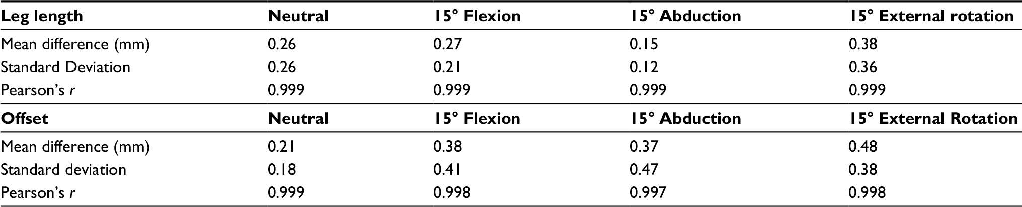 | Table 2 APP benchtop leg length and offset summary of differences Abbreviation: APP, anterior pelvic plane. |
Data regarding offset were also collected, with mean absolute differences of 0.21 mm (SD: 0.18; range: 0.0–0.6 mm), 0.38 mm (SD: 0.41; range: 0.0–1.2 mm), 0.37 mm (SD: 0.47; range: 0.0–1.4 mm), and 0.48 mm (SD: 0.38; range: 0.1–1.4 mm) recorded for neutral, flexed, abducted, and externally rotated phantoms, respectively. A strong relationship was observed between device measurements and the known reference values across all leg positions (r=0.99). Bland–Altman plots for leg length and offset demonstrated excellent agreement for measurements. For leg length values, 91.1% (51/56) of measurements were within the statistical limit of agreement (Figure 6). Similarly, 94.6% (53/56) of offset measurements fell within the statistical limit of agreement (Figure 7).
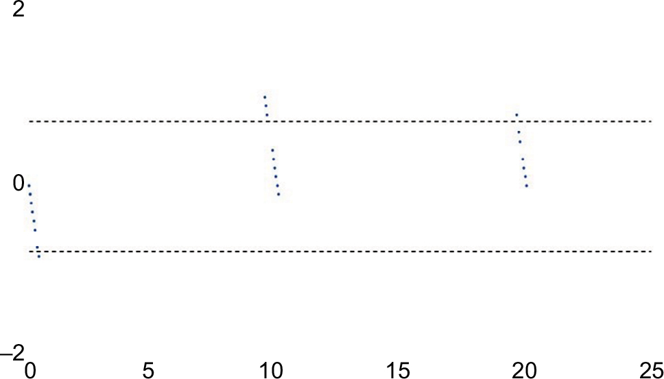 | Figure 6 Bland–Altman plot for APP leg length. Notes: Bland–Altman analysis of leg length demonstrated excellent agreement for measurements. A total of 91.1% (51/56) of measurements were within the statistical limit of agreement (dashed lines). Abbreviation: APP, anterior pelvic plane. |
 | Figure 7 Bland–Altman plot for APP offset. Notes: Bland–Altman analysis of APP offset showed a strong agreement between device and true reference values. A total of 94.6% (53/56) of offset measurements fell within the statistical limit of agreement (dashed lines). Abbreviation: APP, anterior pelvic plane. |
Coronal plane benchtop validation
Anteversion
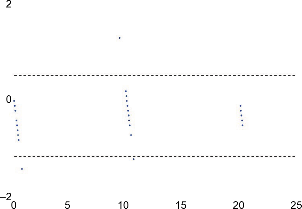
The mean absolute difference between the target reference values and anteversion measurements made by the device probe was 0.42° (SD: 0.29; range: 0.05°–1.05°). The mean absolute difference between the known targeted values and anteversion measurements made by the system impactor was 0.39° (SD: 0.28; range: 0.0°–1.1°). A strong positive relationship was observed between the reference target values and those obtained by the navigation system using the probe and impactor (r=0.99). These results are summarized in Table 3. Bland–Altman analysis demonstrated a strong agreement between measurements. A total of 94.4% (68/72) of paired anteversion measurements fell within the statistical limit of agreement (Figure 8).
 | Figure 8 Bland–Altman plot for supine coronal anteversion. Notes: Bland–Altman analysis of supine coronal anteversion showed excellent agreement between device measurements and true reference values. A total of 94.4% (68/72) of measurements fell within the statistical limit of agreement (dashed lines). |
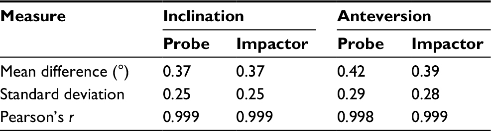 | Table 3 Coronal plane benchtop cup position summary of differences |
Inclination
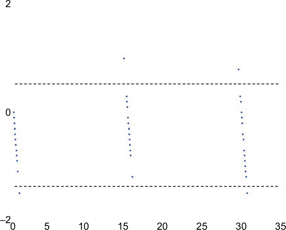
The mean absolute difference between the target values and inclination measurements made by the device probe and impactor were 0.37° (SD: 0.25; range: 0.1°–0.95°) and 0.37° (SD: 0.25; range: 0.0°–1.05°), respectively. As with results for anteversion, a strong linear relationship was observed between measurements obtained by the navigation tool and the reference target inclination values (r=0.99). The results are summarized in Table 3. Bland–Altman analysis demonstrated a strong agreement between measurements. A total of 95.8% (69/72) of paired inclination measurements fell within the statistical limit of agreement (Figure 9).
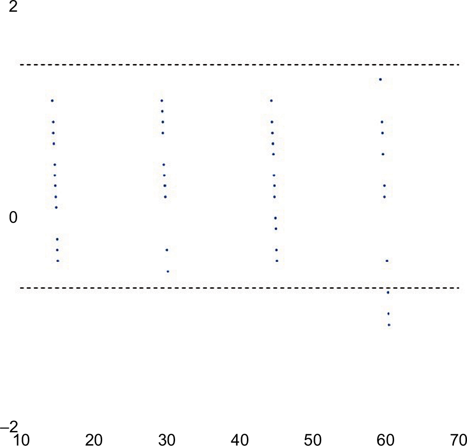 | Figure 9 Bland–Altman plot for supine coronal inclination. Notes: Bland–Altman analysis demonstrated a strong agreement between device measurements and true reference values for supine coronal inclination. A total of 95.8% (69/72) of measurements fell within the statistical limit of agreement (dashed lines). |
Leg length and offset
Mean absolute differences between device leg length measurements and reference measurements were 0.61 mm (SD: 0.57; range: 0.0–2.3 mm), 0.56 mm (SD: 0.32; range: 0.2–1.4 mm), 0.56 mm (SD: 0.35; range: 0.3–1.6 mm), and 0.77 mm (SD: 0.67; range: 0.2–2.3 mm) for neutral, flexed, abducted, and externally rotated phantoms, respectively. Pearson’s r showed a strong relationship across all leg positions for reference values and device leg length measurements (r=0.99). Offset results showed similar results, with absolute mean differences of 0.76 mm (SD: 0.58; range: 0.0–2.0 mm), 0.64 mm (SD: 0.48; range: 0.0–1.8 mm), 0.72 mm (SD: 0.56; range: 0.0–1.8 mm), and 0.85 mm (SD: 0.83; range: 0.0–2.5 mm) recorded for neutral, flexed, abducted, and externally rotated phantoms, respectively. Pearson’s r showed a strong relationship across all leg positions for reference values and device offset measurements (r=0.99). The results are summarized in Table 4. Bland–Altman plots for leg length and offset demonstrated excellent agreement for measurements. For leg length values, 94.6% (53/56) of measurements were within the statistical limit of agreement (Figure 10), whereas 92.8% (52/56) of offset values were within the statistical limit of agreement (Figure 11).
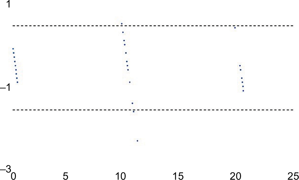 | Figure 10 Bland–Altman plot for supine coronal leg length. Notes: Bland–Altman analysis of supine coronal leg length demonstrated excellent agreement between measurements. A total of 94.6% (53/56) of measurements were within the statistical limit of agreement (dashed lines). |
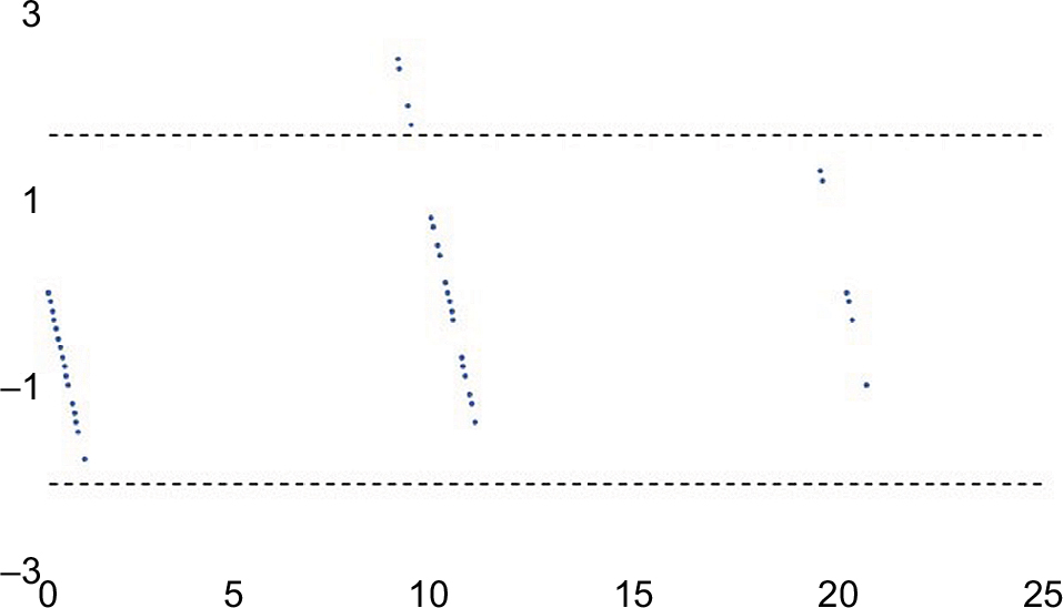 | Figure 11 Bland–Altman plot for supine coronal offset. Notes: Bland–Altman analysis of supine coronal offset demonstrated excellent agreement amongst measurements. A total of 92.8% (52/56) of measurements were within the statistical limit of agreement (dashed lines). |
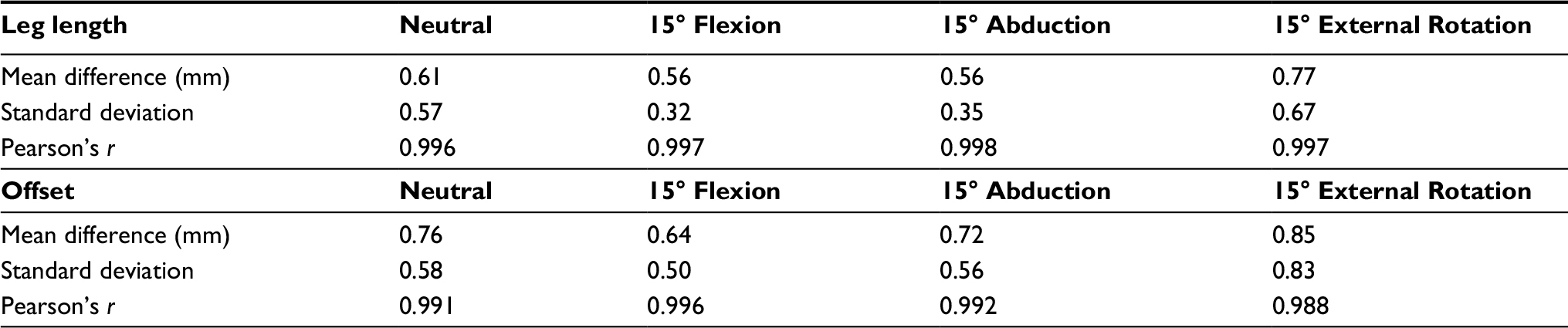 | Table 4 Coronal plane benchtop leg length and offset summary of differences |
Discussion
Dislocation is the most common cause of failure of THA.16,41 Although a number of factors may play a role in its etiology, the most important cause of instability relates to component malpositioning.16 Another issue related to the outcome of THA relates to patient satisfaction and long-term preservation of the prosthetic hip joint. However, surgeons generally lack accurate quantitative measurements for cup position and leg length intraoperatively. The present study evaluated the ability of a novel surgical navigation device to accurately measure cup position and leg length values for THA performed via the anterior surgical approach. The device accurately measured all parameters compared with known target values to within <1° for cup position and 1 mm for leg length and offset parameters, suggesting that this navigation tool may represent a simple and effective solution for measuring inclination, anteversion, and changes in leg length and offset during anterior THA.
Surgeons have traditionally relied on experience, anatomic landmarks, and intraoperative methods such as tissue tensioning to properly select and position prosthetic components during THA. The primary drawback of these methods, however, is that they are not quantifiable. In addition, much of their success is based on surgeon experience and subjective intraoperative feedback. Simple devices such as calipers are available to provide intraoperative measurements on leg length; however, they are associated with the significant limitation of not providing data regarding cup position. This is of particular importance for anterior THA, as it has been described that correctly positioning components may prove difficult when utilizing this approach, given certain patient- and surgery-related factors such as BMI or incision size.7–9
C-arm fluoroscopy is commonly used as an intraoperative monitor in anterior THA, providing surgeons with real-time visualization of the operative hip and assisting with selection and placement of acetabular and femoral components. However, a steep learning curve of up to 100 cases has been described for utilization of C-arm fluoroscopy and anterior THA,23,42–44 and the equipment itself adds the risk of introducing contamination to the surgical field, which could subsequently result in infection.19,20 Similarly, the radiation exposure associated with C-arm usage is an additional risk for patient and OR personnel alike. This factor has been addressed in studies considering the risk of exposure to both the patient and the surgeon.45,46 Surgeons using the anterior approach in THA have been shown to reach half of their recommended maximum radiation exposure of 2000 mrem/year within their first 100 cases.23,47 High-volume surgeons (>189 cases/year) regularly exceed the maximum exposure, thus exposing themselves to potential long-term effects on their overall health.23,47 Given the jurisdictional differences in radiation exposure limitations, which see more stringent limitations internationally versus in the USA,48 and the recently adopted ALARA (As-Low-As-Reasonably-Achievable) philosophy to establish safe radiological practices, any means by which C-arm fluoroscopy use during THA can be minimized should be pursued.
The introduction of computer-assisted navigation for orthopedic surgery has provided surgeons and hospitals with the opportunity to obtain quantifiable, intraoperative measurements for THA and could mitigate the surgical shortcomings of C-arm fluoroscopy, potentially decreasing the reliance on fluoroscopy in the OR. Traditionally, computer-assisted navigation systems have used the APP as a reference plane for cup position measurements,49–53 although more recently, the supine coronal plane has been recommended as an alternative reference plane for these positional measurements.32 An important distinction between these 2 options is that the APP represents an anatomic plane, whereas the coronal plane is a functional plane. This creates different definitions of acetabular position, dictated by the plane in which the measurements are made, as well as measurement in accordance with either anatomic, operative, or radiographic measuring methods.54 Currently, there is no common measurement technique for cup position, thus imposing limitations on the comparison of results among studies and devices.
The challenges regarding registration of the APP have been characterized and relate largely to incorrect or inaccurate identification of the APP landmarks. Richolt et al55 showed that soft tissues overlying bone can result in an error in anteversion measurements of up to 5.5°, whereas Wolf et al53 showed using simulations that a 4 mm error in registering these landmarks could cause deviations of 2° and 7° in inclination and anteversion, respectively. In turn, there may be higher risk with respect to registration of the pubis specifically, as soft tissue thickness surrounding this landmark is, on average, 5.7 mm thicker than soft tissue thickness surrounding the bilateral ASIS.55 Patients with increased soft tissue thickness, thus, may be at risk for malposition of the acetabular cup in these circumstances. In addition, Murray’s definitions54 for acetabular orientation were based on the coronal plane but are frequently used in the literature for studies referencing the APP.50–52 It is noteworthy that radiographic measurements for acetabular cup position are not directly comparable with measurements made using the APP.56 Computer-assisted navigation systems that instead reference the coronal plane may more readily allow for valid comparisons. Our study demonstrated the ability of a novel navigation tool to accurately obtain measurements for cup position, leg length, and offset using the supine coronal plane and thus may represent a viable option that addresses these shortcomings during THA performed via the anterior approach.
The results of the present study showed the device to accurately measure known target values of cup position, leg length, and offset to within 1° and 1 mm, respectively. These findings are comparable to a previous validation study investigating the device in a simulated lateral approach, which showed device accuracy to be within 1° for cup positional measurements and within 1 mm for leg length and offset measurements.33 In addition, a preclinical assessment of the system’s error in a small cadaveric study also showed strong accuracy when compared with CT measurements for cup position.35 Specifically, the navigation tool measured anteversion to within 0.74°, and inclination to within 0.97°, of CT measurements.
Limitations of the present study include the use of phantoms, which may diminish the validity of the results as phantoms do not accurately mirror living tissue. However, the use of phantoms allowed for direct comparison of device measurements with known target values. Obstacles, including intraoperative patient movement, pelvic rotation within radiographs, and image artifact, may otherwise interfere with such measurements when obtained intraoperatively. The benchtop simulations avoided these potential interferences, and our results indicated a very strong relationship between device measurements and the respective known values of the simulations (P=0.99). However, this limitation does highlight the need for future clinical testing.
Clinical studies
Clinical studies investigating the accuracy of the navigation tool are ongoing. Indeed, a comparison between postoperative radiographs and measurements by the navigation tool showed the device to accurately measure leg length to within 0.6 mm.34 Accuracy studies regarding cup position and investigating the navigation tool compared with EOS imaging are currently underway.
Conclusion
In the present study, we addressed the ability of a new navigation device to accurately measure cup position and leg length parameters following simulated anterior THA benchtop validation. In each simulation series, the device was able to accurately measure anteversion, inclination, leg length, and offset to within 1° or 1 mm of the known reference target values. While clinical data are required, these preliminary accuracy results suggest that this navigation tool may be a suitable alternative for anterior THA surgeons seeking ways to shorten or eliminate use of intraoperative C-arm fluoroscopy. In addition, this device provides the opportunity to record measurements for cup position according to either the APP or the supine coronal plane, granting surgeons the choice of using an anatomical or functional reference plane for positional measurements, respectively. These features outline the potential of the device to assist surgeons intraoperatively with anterior THA in the future, with clinical studies currently underway.
Disclosure
JP has received consultancy fees from and has equity in Intellijoint Surgical, Inc. JRB and JMM are employees of and hold stock options in Intellijoint Surgical, Inc. The authors report no other conflicts of interest in this work.
References
Chechik O, Khashan M, Lador R, Salai M, Amar E. Surgical approach and prosthesis fixation in hip arthroplasty world wide. Arch Orthop Trauma Surg. 2013;133(11):1595–1600. | ||
Bergin PF, Doppelt JD, Kephart CJ, et al. Comparison of minimally invasive direct anterior versus posterior total hip arthroplasty based on inflammation and muscle damage markers. J Bone Jt Surg. 2011;93(15):1392–1398. | ||
Bremer AK, Kalberer F, Pfirrmann CW, Dora C. Soft-tissue changes in hip abductor muscles and tendons after total hip replacement. J Bone Jt Surg. 2011;93B(7):886–889.. | ||
Yue C, Kang P, Pei F. Comparison of direct anterior and lateral approaches in total hip arthroplasty: a systematic review and meta-analysis (PRISMA). Medicine (Baltimore). 2015;94(50):e2126. | ||
Martin CT, Pugely AJ, Gao Y, Clark CR. A comparison of hospital length of stay and short-term morbidity between the anterior and the posterior approaches to total hip arthroplasty. J Arthroplasty. 2013;28(5):849–854. | ||
Higgins BT, Barlow DR, Heagerty NE, Lin TJ. Anterior vs. posterior approach for total hip arthroplasty, a systematic review and meta-analysis. J Arthroplasty. 2015;30(3):419–434. | ||
Bender B, Nogler M, Hozack WJ. Direct anterior approach for total hip arthroplasty. Orthop Clin North Am. 2009;40(3):321–328. | ||
Moskal JT, Capps SG, Scanelli JA. Anterior muscle sparing approach for total hip arthroplasty. World J Orthop. 2013;4(1):12–18. | ||
Barrett WP, Turner SE, Leopold JP. Prospective randomized study of direct anterior vs postero-lateral approach for total hip arthroplasty. J Arthroplasty. 2013;28(9):1634–1638. | ||
Elkins JM, Callaghan JJ, Brown TD. The 2014 Frank Stinchfield Award: the “landing zone” for wear and stability in total hip arthroplasty is smaller than we thought: a computational analysis. Clin Orthop Relat Res. 2014;473(2):441–452. | ||
Hart AJ, Allwood SM, Porter M, et al. Which Factors Determine the Wear Rate of Large-Diameter Metal-on-Metal Hip Replacements? J Bone Jt Surg. 2013;95:678–685. | ||
Barrack RL, Krempec JA, Clohisy JC, McDonald DJ RW, Ruh EL NR. Accuracy of acetabular component position in hip arthroplasty. J Bone Jt Surg Am. 2013;95:1760–1768. | ||
Kotwal RS, Ganapathi M, John A, Maheson M, Jones SA. Outcome of treatment for dislocation after primary total hip replacement. J Bone Joint Surg Br. 2009;91(3):321–326. | ||
Matharu GS, Daniel J, Ziaee H, McMinn DJW. Failure of a novel ceramic-on-ceramic hip resurfacing prosthesis. J Arthroplasty. 2015;30(3):416–418. | ||
Ribas M, Cardenas C, Astarita E, Moya E, Bellotti V. Hip resurfacing arthroplasty: mid-term results in 486 cases and current indication in our institution. Hip Int. 2014;24(Suppl 1):S19–S24. | ||
Bozic KJ, Kurtz SM, Lau E, Ong K, Vail TP, Berry DJ. The epidemiology of revision total hip arthroplasty in the United States. J Bone Jt Surg. 2009;91(1):128–133. | ||
Masaoka T, Yamamoto K, Shishido T, et al. Study of hip joint dislocation after total hip arthroplasty. Int Orthop. 2006;30(1):26–30. | ||
Nishii T, Sugano N, Miki H, Koyama T, Takao M, Yoshikawa H. Influence of component positions on dislocation: computed tomographic evaluations in a consecutive series of total hip arthroplasty. J Arthroplasty. 2004;19(2):162–166. | ||
Biswas D, Bible JE, Whang PG, Simpson AK, Grauer JN. Sterility of C-arm fluoroscopy during spinal surgery. Spine (Phila Pa 1976). 2008;33(17):1913–1917. | ||
Gershkovich GE, Tiedeken NC, Hampton D, Budacki R, Samuel SP, Saing M. A comparison of three C-arm draping techniques to minimize contamination of the surgical field. J Orthop Trauma. 2016;30(10): e351–e356.. | ||
De Geest T, Vansintjan P, De Loore G. Direct anterior total hip arthroplasty: complications and early outcome in a series of 300 cases. Acta Orthop Belg. 2013;79(2):166–173. | ||
Hartford JM, Bellino MJ. The learning curve for the direct anterior approach for total hip arthroplasty: a single surgeon’s first 500 cases. Hip Int. 2017;27(5):483–488. | ||
Masonis J, Thompson C. Safe and accurate: learning the direct anterior total hip arthroplasty. Orthopedics. 2008;31(12 Suppl 2):129–135. | ||
Gross A, Muir JM. Identifying the procedural gap and improved methods for maintaining accuracy during total hip arthroplasty. Med Hypotheses. 2016;94:93–98. | ||
Slover JD, Tosteson AN a, Bozic KJ, Rubash HE, Malchau H. Impact of hospital volume on the economic value of computer navigation for total knee replacement. J Bone Joint Surg Am. 2008;90(7):1492–1500. | ||
Brown ML, Reed JD, Drinkwater CJ. Imageless computer-assisted versus conventional total hip arthroplasty: One surgeon’s initial experience. J Arthroplasty. 2014;29(5):1015–1020. | ||
Kalteis T, Handel M, Bäthis H, Perlick L, Tingart M, Grifka J. Imageless navigation for insertion of the acetabular component in total hip arthroplasty: is it as accurate as CT-based navigation? J Bone Jt Surg Br. 2006;88B(2):163–167. | ||
Parratte S, Argenson JA. Validation and usefulness of a computer-assisted cup-positioning system in total hip arthroplasty. A prospective, randomized, controlled study. J Bone Jt Surg. 2007;89(3):494–499. | ||
Ybinger T, Kumpan W, Hoffart HE, Muschalik B, Bullmann W, Zweymüller K. Accuracy of navigation-assisted acetabular component positioning studied by computed tomography measurements: methods and results. J Arthroplasty. 2007;22(6):812–817. | ||
Lee YS, Yoon TR. Error in acetabular socket alignment due to the thick anterior pelvic soft tissues. J Arthroplasty. 2008;23(5):699–706. | ||
Pierrepont J, Walter L, Miles B, et al. Pelvic tilt in the standing, supine and seated positions. In: ISTA 2015 Vienna; 2015:1–3. | ||
Wan Z, Malik A, Jaramaz B, Chao L, Dorr LD. Imaging and navigation measurement of acetabular component position in THA. Clin Orthop Relat Res. 2009;467(1):32–42. | ||
Paprosky WG, Muir JM. Intellijoint HIP®: a 3D mini-optical navigation tool for improving intraoperative accuracy during total hip arthroplasty. Med Devices (Auckl). 2016;9:401–408. | ||
Grosso P, Snider M, Muir JM. A smart tool for intraoperative leg length targeting in total hip arthroplasty: a retrospective cohort study. Open Orthop J. 2016;10(1):490–499. | ||
Vigdorchik J, Cross M, Bogner E, Miller T, Muir J, Schwarzkopf R. A cadaver study to evaluate the accuracy of a new 3D mini-optical navigation tool for total hip arthroplasty. Surg Tech Intl. 2017; 30:1–8. | ||
Krebs V, Incavo SJ, Shields WH. The anatomy of the acetabulum: What is normal? Clin Orthop Relat Res. 2009;467(4):868–875. | ||
Theivendran K, Hart WJ. Is the tip of the greater trochanter a reliable reference for the rotation centre of the femoral head in total hip arthroplasty? Acta Orthop Belg. 2009;75(4):472–476. | ||
Bland JM, Altman DG. Statistical methods for assessing agreement between two methods of clinical measurement. Lancet (London, England). 1986;1(8476):307–310. | ||
Altman D, Bland J. Measurement in medicine: the analysis of method comparison studies. Statistician. 1983;32:307–317. | ||
Giavarina D. Understanding Bland Altman analysis. Biochem Med. 2015;25(2):141–151. | ||
Plate JF, Brown ML, Wohler AD, Seyler TM, Lang JE. Patient factors and cost associated with 90-Day readmission following total hip arthroplasty. J Arthroplasty. 2016;31(1):49–52. | ||
Rathod PA, Bhalla S, Deshmukh AJ, Rodriguez JA. Does fluoroscopy with anterior hip arthoplasty decrease acetabular cup variability compared with a nonguided posterior approach? Clin Orthop Relat Res. 2014;472(6):1877–1885. | ||
Seng BE, Berend KR, Ajluni AF, Lombardi AV. Anterior-supine minimally invasive total hip arthroplasty: defining the learning curve. Orthop Clin North Am. 2009;40(3):343–350. | ||
Homma Y, Baba T, Kobayashi H, et al. Safety in early experience with a direct anterior approach using fluoroscopic guidance with manual leg control for primary total hip arthroplasty: a consecutive one hundred and twenty case series. Int Orthop. 2016;40(12):2487–2494. | ||
Pomeroy CL, Mason JB, Fehring TK, Masonis JL, Curtin BM. Patient radiation exposure during fluoro-assisted direct anterior approach total hip arthroplasty. J Arthroplasty. 2015;31(6):1218–1221. | ||
Pomeroy CL, Mason JB, Fehring TK, Masonis JL, Curtin BM. Radiation exposure during fluoro-assisted direct anterior total hip arthroplasty. J Arthroplasty. 2015;31(8):1742–1745. | ||
Singer G. Occupational radiation exposure to the surgeon. J Am Acad Orthop Surg. 2005;13(1):69–76. | ||
Rhea EB, Rogers TH, Riehl JT. Radiation safety for anaesthesia providers in the arthopaedic operating room. Anaesthesia. 2016;71:455–461. | ||
Jaramaz B, DiGioia AM 3rd, Blackwell M, Nikou C. Computer assisted measurement of cup placement in total hip replacement. Clin Orthop Relat Res. 1998;(354):70–81. | ||
DiGioia AM, Jaramaz B, Blackwell M, et al. The Otto Aufranc Award. Image guided navigation system to measure intraoperatively acetabular implant alignment. Clin Orthop Relat Res. 1998;(355):8–22. | ||
Digioia AM, Jaramaz B, Plakseychuk AY, et al. Comparison of a mechanical acetabular alignment guide with computer placement of the socket. J Arthroplasty. 2002;17(3):359–364. | ||
Dorr LD, Hishiki Y, Wan Z, Newton D, Yun A. Development of imageless computer navigation for acetabular component position in total hip replacement. Iowa Orthop J. 2005;25:1–9. | ||
Wolf A, Digioia AM 3rd, Mor AB, Jaramaz B. Cup alignment error model for total hip arthroplasty. Clin Orthop Relat Res. 2005;(437):132–137. | ||
Murray DW. The definition and measurement of acetabular orientation. J Bone Joint Surg Br. 1993;75(2):228–232. | ||
Richolt JA, Effenberger H, Rittmeister ME. How does soft tissue distribution affect anteversion accuracy of the palpation procedure in image-free acetabular cup navigation? An ultrasonographic assessment. Comput Aided Surg. 2005;10(2):87–92. | ||
Lembeck B, Mueller O, Reize P, Wuelker N. Pelvic tilt makes acetabular cup navigation inaccurate. Acta Orthop. 2005;76(4):517–523. |
 © 2018 The Author(s). This work is published and licensed by Dove Medical Press Limited. The
full terms of this license are available at https://www.dovepress.com/terms
and incorporate the Creative Commons Attribution
- Non Commercial (unported, 3.0) License.
By accessing the work you hereby accept the Terms. Non-commercial uses of the work are permitted
without any further permission from Dove Medical Press Limited, provided the work is properly
attributed. For permission for commercial use of this work, please see paragraphs 4.2 and 5 of our Terms.
© 2018 The Author(s). This work is published and licensed by Dove Medical Press Limited. The
full terms of this license are available at https://www.dovepress.com/terms
and incorporate the Creative Commons Attribution
- Non Commercial (unported, 3.0) License.
By accessing the work you hereby accept the Terms. Non-commercial uses of the work are permitted
without any further permission from Dove Medical Press Limited, provided the work is properly
attributed. For permission for commercial use of this work, please see paragraphs 4.2 and 5 of our Terms.