Back to Journals » Medical Devices: Evidence and Research » Volume 13
A New Methodology for the Digital Planning of Micro-Implant-Supported Maxillary Skeletal Expansion
Authors Cantarella D ![]() , Savio G
, Savio G ![]() , Grigolato L, Zanata P, Berveglieri C, Lo Giudice A, Isola G
, Grigolato L, Zanata P, Berveglieri C, Lo Giudice A, Isola G ![]() , Del Fabbro M, Moon W
, Del Fabbro M, Moon W
Received 30 January 2020
Accepted for publication 4 March 2020
Published 18 March 2020 Volume 2020:13 Pages 93—106
DOI https://doi.org/10.2147/MDER.S247751
Checked for plagiarism Yes
Review by Single anonymous peer review
Peer reviewer comments 2
Editor who approved publication: Dr Scott Fraser
Daniele Cantarella,1 Gianpaolo Savio,2 Luca Grigolato,2 Paolo Zanata,3 Chiara Berveglieri,4 Antonino Lo Giudice,5,6 Gaetano Isola,5 Massimo Del Fabbro,1 Won Moon7
1Department of Biomedical, Surgical and Dental Sciences, University of Milan, Milan, Italy; 2Department of Civil, Environmental and Architectural Engineering ICEA, University of Padova, Padova, Italy; 3Private Practice, Castelfranco Veneto, Italy; 4Private Practice of Orthodontics, Bondeno, Italy; 5Department of General Surgery and Surgical-Medical Specialties, Section of Orthodontics, School of Dentistry, University of Catania, Catania, Italy; 6Department of Biomedical and Dental Sciences and Morphofunctional Imaging, Section of Orthodontics, University of Messina, Messina, Italy; 7Division of Growth and Development, Section of Orthodontics, School of Dentistry, Center for Health Science, University of California, Los Angeles, Los Angeles, CA, USA
Correspondence: Daniele Cantarella
Department of Biomedical, Surgical and Dental Sciences, University of Milan, Via Commenda 10, Milan, Italy
Email [email protected]
Introduction: Miniscrew-assisted rapid palatal expansion (MARPE) appliances utilize the skeletal anchorage to expand the maxilla. One type of MARPE device is the Maxillary Skeletal Expander (MSE), which presents four micro-implants with bicortical engagement of the palatal vault and nasal floor. MSE positioning is traditionally planned using dental stone models and 2D headfilms. This approach presents some critical issues, such as the inability to identify the MSE position relative to skeletal structures, and the potential risk of damaging anatomical structures.
Methods: A novel methodology has been developed to plan MSE position using the digital model of dental arches and cone-beam computed tomography (CBCT). A virtual model of MSE appliance with the four micro-implants was created. After virtual planning, a positioning guide is virtually designed, 3D printed, and utilized to model and weld the MSE supporting arms to the molar bands. The expansion device is then cemented in the patient oral cavity and micro-implants inserted. A clinical case of a 12.9-year-old female patient presenting a Class III malocclusion with transverse and sagittal maxillary deficiency is reported.
Results: The midpalatal suture was opened with a split of 3.06 mm and 2.8 mm at the anterior and posterior nasal spine, respectively. After facemask therapy, the sagittal skeletal relationship was improved, as shown by the increase in ANB, A-Na perpendicular and Wits cephalometric parameters, and the mandibular plane rotated 1.6° clockwise.
Conclusion: The proposed digital methodology represents an advancement in the planning of MSE positioning, compared to the traditional approach. By evaluating the bone morphology of the palate and midface on patient CBCT, the placement of MSE is improved regarding the biomechanics of maxillary expansion and the bone thickness at micro-implants insertion sites. In the present case report, the digital planning was associated with a positive outcome of maxillary expansion and protraction in safety conditions.
Keywords: miniscrew-assisted rapid palatal expansion, MARPE, CBCT, MSE, virtual planning, cephalometrics-based digital planning, CBDP, workflow, TAD
Introduction
Digital technology in orthodontics is becoming continuously more important, changing the rules of conventional workflow.1–5 Every process in patient management is progressively translated into the virtual environment, from the diagnosis and treatment outcome pre-visualization to the customization of appliance design and the personalization of the therapy.4–7
There are several benefits to the application of a digital workflow. First, the use of intraoral scanners permits the production of digital models of the dental arches, thus reducing the need for fabrication of physical models.8 Furthermore, the utilization of the cone beam computer tomography (CBCT) technology allows a more detailed diagnosis compared to the conventional one made with 2D radiographs and cephalometric analysis. Intra-oral digital models, CBCT imaging, and 3D facial scan enable the analysis of the dentition, skeletal structures, and facial soft tissues in the three dimensions of space, increasing the details and the accuracy of the orthodontic setup.7,9 Also, the digital manufacturing technology related to 3D printing and metal laser melting allows a completely unrestricted design and personalization of the orthodontic devices and appliances,6,8,10 which traditionally have been a custom-made laboratory work. The large and continuously growing range of materials for 3D printers permits to expand the choice for the needed application, moving away from the usual orthodontic materials such as stainless steel, titanium alloys, or acrylic resin.
Implant dentistry is a field in which the digital workflow has been widely applied.11,12 In the “computer-guided” implant placement approach, virtual planning of implants’ positions and 3D printed customized surgical guides are used to help the clinician improve the accuracy of implants positioning in the jaw bones during the surgical phase.13,14 In orthodontics, the placement of micro-implants with a 3D method based on CBCT imaging has been described in recent years.15,16 The methodology allows to gather information on the anatomy of the area intended for insertion, and to select a site with adequate bone quantity and quality. 3D surgical guides are additively manufactured and then used to place the micro-implants into the maxillary bone, for the subsequent application of several orthodontic devices, including micro-implant-assisted rapid palatal expansion (MARPE) appliances, which utilize the skeletal anchorage to expand the maxilla in the transverse dimension. In addition, MARPE devices are used in association with the facemask to enhance the maxillary protraction, especially in patients older than 8–9 years of age.17–20
The present paper aims to describe a novel procedure to position a particular type of MARPE appliance, the Maxillary Skeletal Expander (MSE),20–26 in the patient’s oral cavity through digital planning and workflow.
Methods
A written informed consent to participate in the study and to publish the case details and the images was given by the patient’s legal guardians. Institutional approval to publish the case details was not needed.
A digital methodology is described by showing the treatment of a patient that presented a Class III malocclusion (Figures 1 and 2). The patient was 12 years and 9 months old, and her chief complain was chin protrusion, midface retrusion, underbite, and spacings between teeth. Intra-oral examination revealed a Class III molar and canine relationship on both right and left sides, 6 mm spacing in the upper dental arch, 7 mm spacing in the lower dental arch, 1.5 mm overjet and overbite, maxillary midline shift of 1 mm to the left. The maxilla appeared constricted in the transverse dimension, with a crossbite on the right side at the level of the maxillary first molar, second premolar, canine and lateral incisor. The cephalometric analysis (Table 1) showed a severe Class III skeletal malocclusion due to retruded maxilla (Wits appraisal of – 6.5 mm), with mesocephalic vertical pattern, proclination of upper incisors and retroclination of lower incisors.
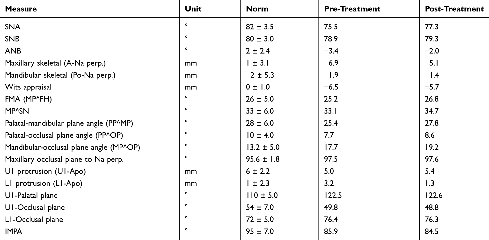 |
Table 1 Cephalometric Analysis |
 |
Figure 1 Patient initial facial and intraoral photos. |
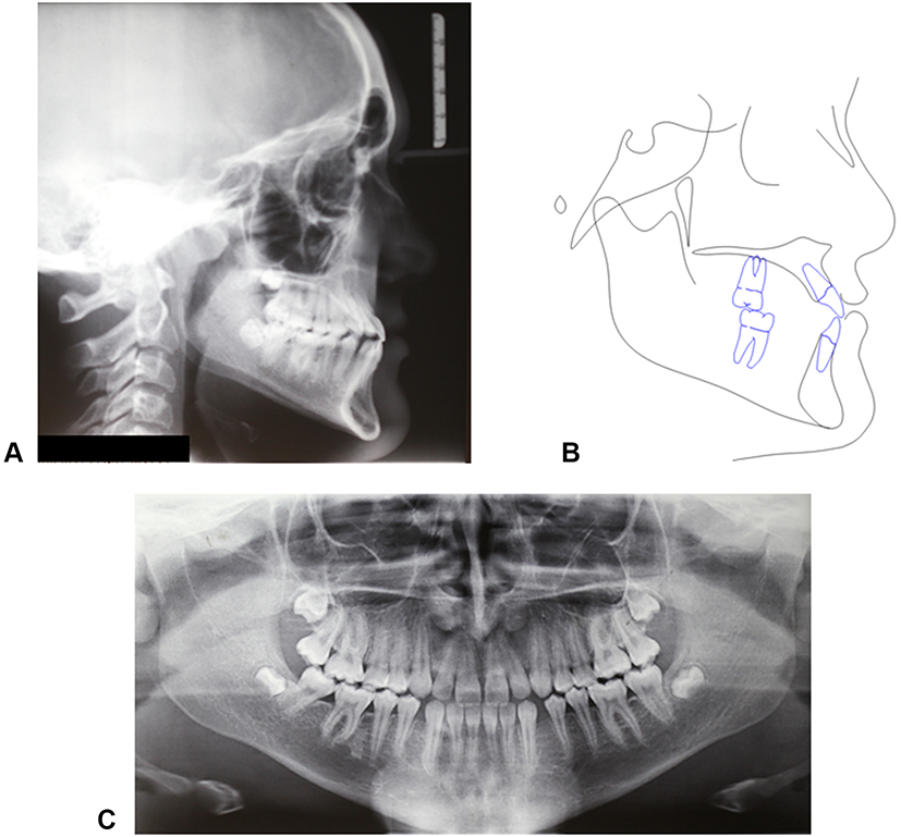 |
Figure 2 Initial records of the patient. (A) Lateral headfilm. (B) Cephalometric tracing. (C) Panoramic radiograph. |
The treatment plan was to expand and protract the maxilla with MSE (BioMaterials Korea, Seoul, Korea) followed by facemask therapy. MSE appliance presents a body with the expansion jackscrew and four slots where micro-implants are inserted, and four connecting arms to the molar bands.23,24 The use of four miniscrews in the MSE appliance helps to disarticulate the pterygopalatine suture, which is a major resistance structure that hampers the forward maxillary movement during facemask therapy.24 The alternative treatment modality was orthognathic surgery at an older age, an option that was rejected by the patient, who chose the more conservative treatment with MSE and facemask.
A cone-beam computed tomography (CBCT) of the patient maxilla was taken with HyperionX9 scanner (MyRay, Imola, Italy) with a reduced field of view (FOV) of 5 cm x 11 cm to limit the patient exposure to radiations. The impressions of patient dental arches were taken with alginate material, and stone models were poured. The models were then scanned with Optical Revenge Dental device (Open Technologies, Brescia, Italy). The skull CBCT DICOM file was converted into an STL file with VG Studio Max software (Volume Graphics GmbH, Heidelberg, Germany). Then, the CBCT and dental arches STL files were aligned at first manually by overlapping three landmarks and then globally with Geomagic Studio 12 software (3D Systems, Morrisville, Carolina del Nord, USA) as shown in Figure 3. The combined model of CBCT and dental arches was imported in Rhinoceros (v. 6) software (Robert McNeel & Associates, Seattle, Washington USA).
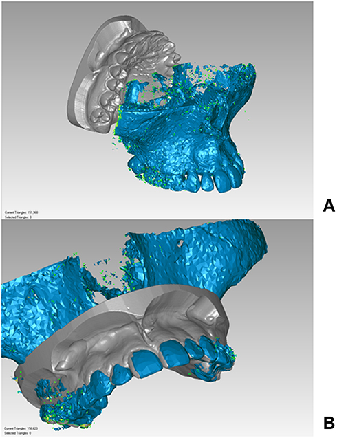 |
Figure 3 STL files of CBCT and dental arches. (A) before alignment. (B) After alignment. |
At this point, reference planes are identified in the bony structures of the patient midface, to create the x, y, z coordinate system of the maxilla. The first plane is the Midsagittal Plane (MP), passing through the points Midpalatal Suture 5 (MS5), Midpalatal Suture 7 (MS7), and Vomer Posterior (VP) (Figure 4A and B). The reference points are defined as follows: MS5 is the point placed on the oral side of the midpalatal suture at the level of second premolars; MS7 is the point placed on the oral side of the midpalatal suture at the level of second molars; VP is the most posterior point of the vomer.
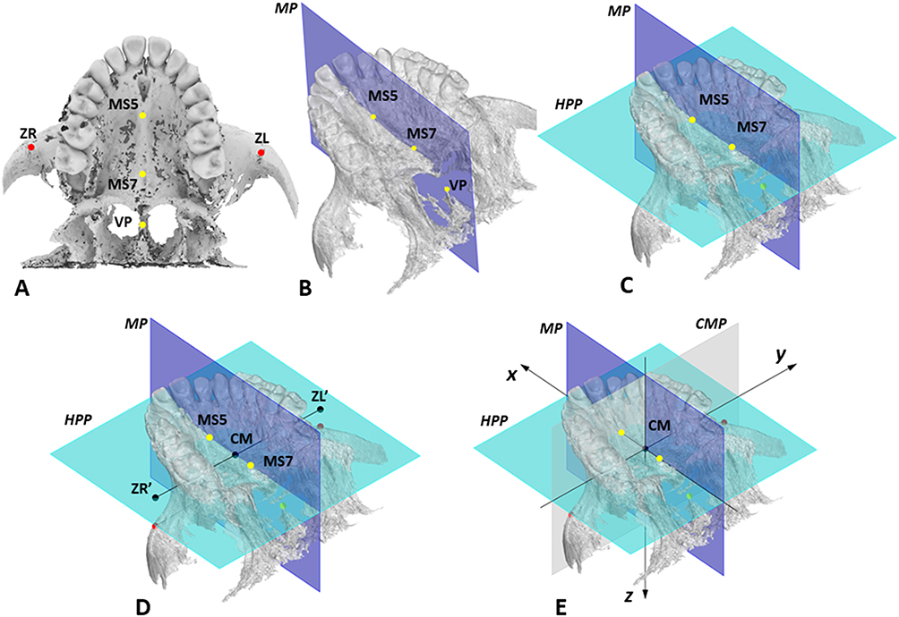 |
Figure 4 Determination of reference planes and axes on the maxilla. (A) Skeletal landmarks utilized: point on oral aspect of midpalatal suture at the level of second premolars (MS5) and second molars (MS7), most posterior point of vomer (VP), most lateral point of the zygomatic process of the maxilla on the right (ZR) and left side (LZ). (B) Midsagittal plane (MP), in blue, passing through MS5, MS7, and VP. (C) Horizontal palatal plane (HPP), in light blue, perpendicular to MP and passing through MS5 and MS7. (D) Center of Maxilla (CM) point, defined by the intersection of the projection of the bizygomatic line (ZR’-ZL’) to HPP and posterior part of midpalatal suture (MS5-MS7 line). (E) CM point as the origin of the x, y, z coordinate system of the maxilla. |
The Horizontal Palatal Plane (HPP) is identified as the plane perpendicular to the Midsagittal Plane (MP) and passing through MS5 and MS7 (Figure 4C).
Then, the bi-zygomatic line (BZL) connecting the most lateral point of the zygomatic process of the maxilla on the right and left side (ZR and ZL, respectively) is drawn, and the line is orthogonally projected to the horizontal palatal plane (HPP). On this plane, the intersection between the projection of the BZL and the midpalatal suture (MS4-MS7 line) is named the Center of Maxilla (CM) point (Figure 4D).
A coronal plane, called Coronal Maxillary Plane (CMP), which is perpendicular to the Midsagittal Plane (MP) and to the Horizontal Palatal Plane (HPP) and passing through the CM point represents the third plane of the maxillary x, y, z coordinate system (Figure 4E), and CM point represents the origin of the system (Figure 4E).
The virtual model of the MSE appliance was designed using Rhinoceros software (Figure 5A). The MSE model is a single file that includes both the body of the expander and the four micro-implants, which are represented by four cylinders 13 mm long that have a notch, i.e., become thinner, at the level of 11 mm. The groove allows simple visualization of the micro-implant length (11 mm versus 13 mm) during the MSE setting procedure in the CBCT.
 |
Figure 5 Setting of MSE in the maxilla in the initial default position. (A) Virtual model of MSE appliance with 4 micro-implants; the center of the appliance (CA), the light blue dot, is computed as the midpoint of the center of 4 micro-implant slots (yellow dots) and is set as the origin of MSE coordinate system. (B) MSE located in the initial default position in the maxilla, in which the CA point is coincident with the center of maxilla (CM) point, and the MSE x’, y,’ z’ coordinate system is aligned with the maxilla x, y, z system. |
An x’, y,’ z’ coordinate system is also generated for the MSE virtual model (Figure 5A), and the origin of the system is set at the Center of MSE Appliance (CA) point, which is given by the midpoint of the center of 4 slots for micro-implants in the mucosal face of appliance body.
The MSE model was then positioned in the maxilla in an initial default position so that the CA point is coincident with the CM point, and in which the x’, y,’ z’ coordinate system of the MSE appliance is aligned with that of the maxilla (Figure 5B).
A user interface has been developed (Figure 6A), with which the position and inclination of the MSE appliance can be changed from its initial default setting. The MSE position can be modified by moving the CA along the x, y, z axes of the maxilla (Figure 4E), while the MSE inclination can be modified by changing the appliance Yaw, Pitch and Roll (Figure 6B). The terminology used for the appliance inclination is derived from the conventional skull orientation terms:27 Yaw is defined as the rotation around the vertical axis, Pitch as the rotation around the transverse axis, and Roll as the rotation around the sagittal axis.
 |
Figure 6 (A) User interface developed with Rhinoceros software, with which the inclination (Yaw, Pitch, and Roll) and position (dx, dy, dz) of MSE appliance can be changed to optimize the bone thickness (BT) at the level of the 4 micro-implants identified with numbers 1–4, the appliance distance from the palatal mucosa (DM), the micro-implant length required to obtain bicortical engagement (ML) and the guiding bar interference (GBI). (B) yaw, pitch, roll, and reference axes for MSE. |
The position and inclination of MSE appliance were changed from the initial default setting, taking into consideration the following parameters: bone thickness at the level of the four micro-implants (BT), appliance distance from palatal mucosa (DM), minimum micro-implant length for bicortical engagement (ML) and guiding bar interference (GBI) with palatal mucosa, as shown in Figure 7 and Table 2. As MSE appliance was moved or inclined, the user interface gave in real-time the measurements of the parameters to be evaluated.
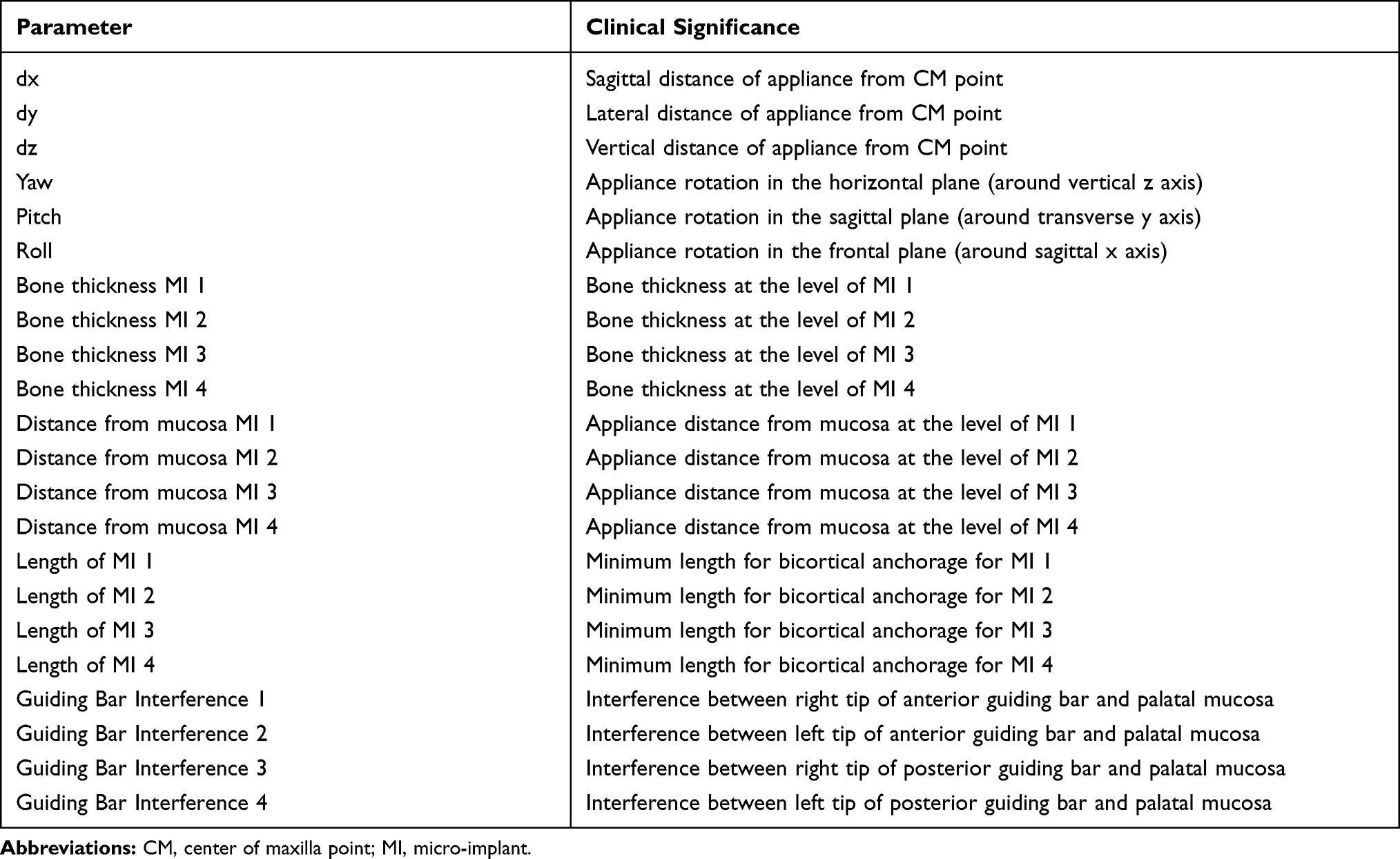 |
Table 2 Parameters Utilized for the Digital Planning of MSE Position and Inclination, and Their Clinical Significance |
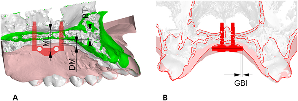 |
Figure 7 Parameters analyzed during the digital planning of MSE position and inclination: minimum micro-implant length required to obtain bicortical anchorage (ML), appliance distance from palatal mucosa (DM), bone thickness at the level of the micro-implant insertion sites (BT), guiding bar interference (GBI) with palatal mucosa. (A) sagittal section. (B) coronal section. |
A final position and inclination of MSE were identified for the patient (Figure 8A). The parameters’ last values are displayed in Figure 6A. Then, a 3D positioning guide was designed on top of the virtual model of dental arches with final MSE position (Figure 8B), the virtual guide was 3D printed with Grey resin (Formlabs, Somerville, USA), the MSE appliance was inserted into the resin positioning guide and secured with steel-ligature (Figure 8C), and finally, the guide and the appliance were placed on the stone model for the bending and welding of the appliance arms to the molar bands (Figure 8D).
 |
Figure 8 Lab work for MSE. (A) Virtual model with the final position of MSE after digital planning. (B) Digital design of positioning guide. (C) Fixation of the MSE appliance in the positioning guide with steel ligatures. (D) Positioning of the MSE appliance on the dental stone model by means of the resin guide for bending and welding of MSE arms. |
The finalized appliance (Figure 9A) was cemented in the patient oral cavity, and subsequently, 4 micro-implants 11 mm long were inserted through the appliance slots into the palatal bone (Figure 9B). The appliance itself acts as a surgical guide; hence the micro-implants are embedded in the palate in the same position that was selected on the CBCT during the virtual planning.
 |
Figure 9 (A) Finalized MSE appliance on the dental stone model. (B) MSE appliance after placement in the patient oral cavity. (C) Intraoral picture after maxillary expansion. |
MSE activation consisted of 2 turns in the morning and two turns in the evening (0.13 mm expansion per turn) until an inter-incisal diastema appeared and then two turns in the evening until expansion completion (Figure 9C); the total appliance activation was 4 mm. Maxillary protraction with the facemask was performed immediately after completion of maxillary expansion. A force of 16 ounces was applied bilaterally, by means of 2 elastics with a diameter of 3/8’ attached to the intra-oral hooks (Figure 10). Facemask wear time was 14–16 hrs per day. Treatment with fixed orthodontic appliance will start immediately after the facemask therapy. The fixed orthodontic treatment will have the purpose of closing the remaining dental diastemas and, if needed, to provide retention for the sagittal skeletal correction by means of intermaxillary elastics.
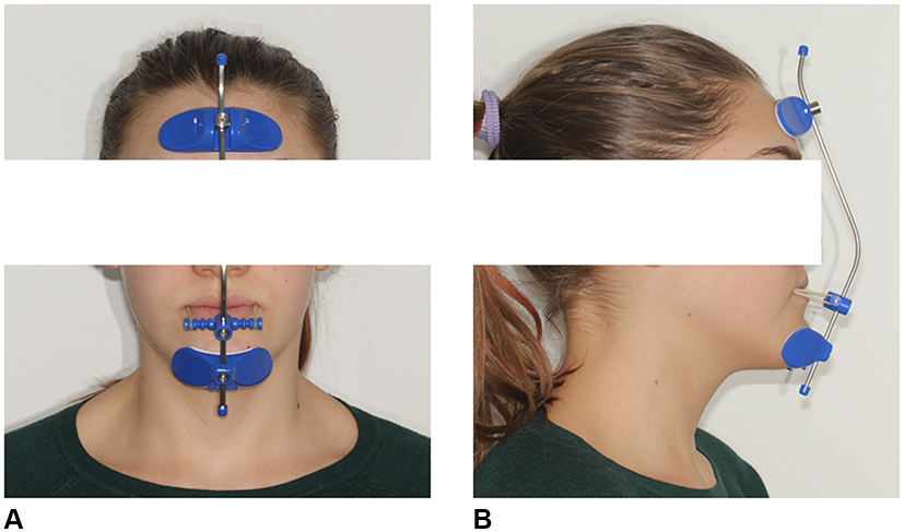 |
Figure 10 Patient wearing the facemask. (A) Frontal view. (B) Lateral view. |
Results
A CBCT with 5x11 cm FOV was taken immediately after completion of active maxillary expansion, before the start of maxillary protraction with the facemask, and an axial palatal section showed the opening of the mid palatal suture, with a split of 3.06 mm and 2.8 mm at anterior nasal spine and posterior nasal spine, respectively (Figure 11). After facemask therapy, which lasted 7 months, the sagittal skeletal relationship was improved as indicated by the increase in ANB, A-Nasion perpendicular, and Wits cephalometric parameters (Table 1 and Figure 12). Regarding the skeletal vertical dimension, the mandibular plane rotated 1.6° in a clockwise direction as shown by the increase in FMA and MP^SN angles (Table 1). With regards to the occlusion, the lateral cross-bite was resolved, the OVJ was over-corrected from 1.5 mm to 3.9 mm (Figure 13). The remaining diastemas will be closed through a following orthodontic treatment with fixed appliances.
 |
Figure 11 Patient CBCT after expansion, before the start of maxillary protraction. (A) Axial palatal section. (B) Maxilla 3D rendering. |
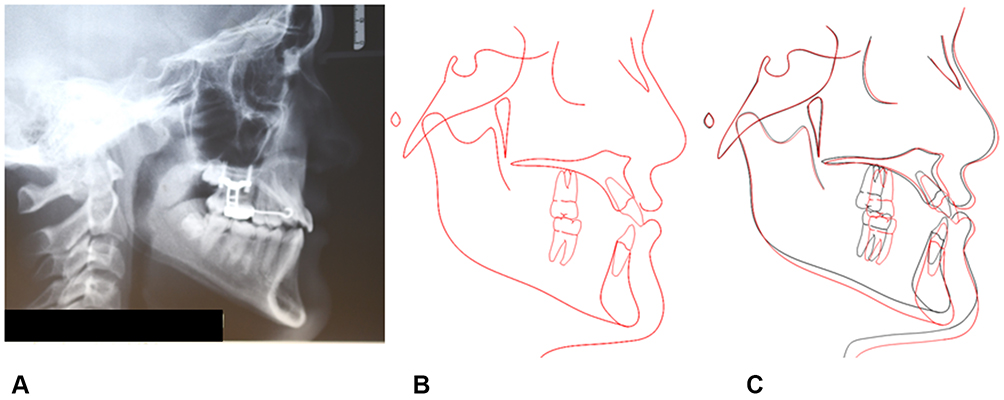 |
Figure 12 Final records of the patient. (A) Final lateral headfilm. (B) Final cephalometric tracing. (C) Superimposition of pre-treatment (black) and post-treatment (red) cephalometric tracings on anterior cranial base at Sella. |
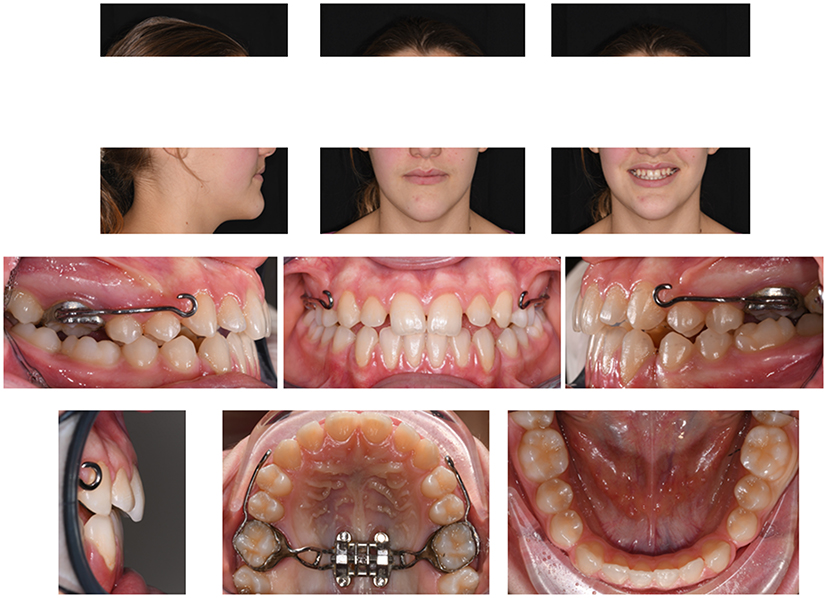 |
Figure 13 Facial and intraoral pictures after facemask therapy. |
Discussion
In recent years, digital planning and workflow in orthodontics made the positioning of micro-implants easier and safer.15,16 Guiding criteria are the maximization of cortical bone quantity at the micro-implant sites and avoidance of critical anatomical structures such as nerve or artery bundles, dental roots, maxillary sinuses. In the digital workflows described in the literature, micro-implants are virtually placed on the patient CBCT, and then a surgical guide for their insertion in the patient oral cavity is 3D printed and used by the orthodontist during the surgical phase. The maxillary expander is subsequently positioned and secured with fixation screws on top of micro-implant heads.
Traditionally, the MSE position is planned with the use of conventional dental stone models and 2D headfilms. This approach presents some critical issues, such as the inability to identify the location of MSE relatively to midface skeletal structures, and the potential risk of affecting with the micro-implants particular anatomical areas, like the nasal septum, that should be avoided. On the other hand, the digital workflows adopted for other MARPE devices15,16 cannot be utilized for MSE because the micro-implants are inserted after the MSE cementation in the oral cavity. In the present study, a virtual model of the entire MSE appliance, including the body with the expansion jackscrew and the 4 micro-implants, was designed, and its position planned in the patient CBCT. The use of the whole appliance allows us to analyze the thickness of palate bone at the level of the 4 micro-implants and simultaneously the setting (position and inclination) of the appliance expansion force vector relative to the bony structures of the maxilla and midface.
In the protocol developed, the center of MSE appliance and hence the expansion force vector is set by default in the same position as the CM point, defined by the projection of the bizygomatic line (BZL) on the posterior part of the midpalatal suture. In the literature, it has been described that the pterygopalatine suture28,29 and the zygomatic buttress bone23–26,30,31 are two major resistance structures that hamper the lateral maxillary movement. Furthermore, Lee et al32 have shown that the center of resistance of the maxillary halves is located slightly superiorly and laterally to the root apex of maxillary second molars, close to the most lateral point of the zygomatic process of the maxilla (ZR and ZL) utilized in our protocol. In the present study, the choice of ZR and ZL points, rather than the location described by Lee et al,32 was dictated by the fact that they could be identified more clearly on the patient CBCT. The application of the expansion force vector close to the maxillary center of resistance has the scope of maximizing the orthopedic effect on the midface during maxillary expansion.23–26 If the CA is moved forward relative to the CM point, the midpalatal suture opening will be less parallel and more V-shaped, since the force vector will act in a more anterior part of the maxilla, away from its center of resistance.32
Although MSE position relative to the bizygomatic line and CM point is the main objective of the digital planning due to biomechanical reasons, other parameters were taken into consideration. The bone thickness at the level of the 4 micro-implants (BT) is an important factor to increase their primary stability (Figure 7A). For this parameter, MSE was moved from the initial default position, with the scope of maximizing the bone thickness at micro-implant insertion sites.
The parameter “appliance distance from palatal mucosa” (DM) (Figure 7A) defines the distance of the mucosal appliance aspect of 4 micro-implant slot centers from the palatal mucosa. This distance ideally should be equal to zero, to minimize the leverage effect produced on the micro-implants during the appliance activation. Anyway, due to the uneven palatal surface, some appliance slot centers may lay at different distances, and hence a discrepancy of 0–2 mm was considered acceptable for this parameter.
The parameter “micro-implants length” (ML) (Figure 7A) represents the minimum micro-implant length to penetrate the cortical bone layers of both palatal vault and nasal floor to achieve a bicortical skeletal anchorage. The measurements of this parameter were utilized to choose the length for the 4 micro-implants. Bicortical skeletal anchorage is required for the correct functioning of MSE, since it increases the stability of micro-implants.20–26 Loss of skeletal anchorage stability and bending of micro-implants is a negative consequence of monocortical anchorage,22 that seriously compromises the outcome of the therapy in adults and potentially also in growing patients.
Regarding the inclination of MSE, the appliance is set by default in its initial position in such a way that the MSE coordinate system is coincident with that of the maxilla. This event generates the parallelism between the 4 micro-implants, the midsagittal plane (MP) and the nasal septum (Figure 14A). When the inclination of the MSE appliance was modified to improve the values of other variables, the Roll parameter was changed by a minimal amount, to avoid the proximity of micro-implants with the nasal septum.
 |
Figure 14 MSE initial default position. (A) Parallelism between the micro-implants and the midsagittal plane (MP) and nasal septum. (B) MSE expansion force vector (yellow arrow) positioned perpendicularly to the midpalatal suture. |
Another important inclination parameter is “Yaw,” which represents the rotation of the MSE appliance in the horizontal plane around a vertical axis (Figure 6B). Changes in Yaw reflect a modification in the direction of the MSE expansion force vector relative to the midpalatal suture (MS5-MS7 line) (Figure 14B) and may generate an uneven force distribution on two maxillary halves and an asymmetric expansion.24 Hence, also for Yaw, the change from its initial setting was minimized.
Finally, guiding bar interference (GBI) represents the amount of penetration of appliance guiding bar tips into the palatal mucosa, and in the presented clinical case, the bar tips were trimmed by the corresponding amount displayed in Figure 6A, to avoid tissue impingement.
In the proposed methodology, the resin positioning guide (Figure 8) is used solely by the dental lab technician to fabricate the MSE appliance and not by the orthodontist, since micro-implants are placed after the MSE cementation in the oral cavity, and the appliance itself acts as a surgical guide. The CBCT taken after maxillary expansion (Figure 11B) showed the miniscrews on the sides of the midpalatal suture, without the involvement of the nasal septum area.
Compared to the traditional approach, the methodology presented to position MSE with digital planning based on CBCT has the advantage of increasing the precision and safety of the procedure, taking into consideration anatomical as well as biomechanical factors. Furthermore, the methodology serves to plan the micro-implant-supported maxillary skeletal expansion with objectively measurable parameters and can also be used as a tool for research purposes on large adult patient samples. Future studies will be needed to define the range of acceptability for the selected parameters and the extent to which they can affect the efficacy of maxillary skeletal expansion.
We acknowledge that a limitation of this methodology is the use of CBCT imaging, which exposes the patient to additional radiations. Routine use of CBCT cannot be accepted in young patients, but its use can be justified on a patient case individual basis.33 The patient’s exposure to radiation can be greatly reduced by the choice of a FOV as small as possible (5 x 11 cm) in the CBCT. This is particularly recommended in subjects under 18 years of age.34 Such FOV is large enough to select the skeletal landmarks required for the virtual positioning of MSE. This inconvenience is compensated by the added safety of the methodology, which allows to avoid the involvement of particular anatomical areas like the nasal septum, and to maximize bone thickness at miniscrew insertion sites, for a higher stability of the skeletal anchorage during treatment.
The novelty of the methodology presented in this research is that a digital planning and workflow have been developed specifically for the MSE appliance. Furthermore, for the first time a cephalometrics-based digital planning (CBDP) has been adopted, in which cephalometric landmarks and reference planes are utilized to orient the expansion force vector relative to midface skeletal structures. In the study, 3 different softwares were utilized, which is time-consuming for the operator. For the use in the routine orthodontic clinical practice, it is advisable that the functions be unified in a single software to make the methodology more efficient. Furthermore, the STL file of the patient CBCT was utilized, since it allowed a more straightforward workflow with Rhinoceros software. Further studies with CBCT DICOM files that permit better visualization of bone quality (cortical versus cancellous) are advocated.
Conclusions
- A novel methodology was developed to digitally plan the position and inclination of MSE appliance, inclusive of the 4 micro-implants, concerning the patient midface CBCT
- In the method, parameters related to micro-implants insertion sites as well as to biomechanical factors were utilized
- In the present case report, the digital planning of MSE positioning was associated with a positive outcome of midpalatal suture opening and maxillary advancement with MSE and facemask, in safety conditions
Abbreviations
MARPE, Miniscrew-assisted rapid palatal expansion; MSE, maxillary skeletal expander; CBCT, cone-beam computed tomography; FOV, field of view; DICOM, digital imaging and communications in medicine; STL, standard tessellation language; MP, midsagittal plane; MS5, midpalatal suture 5; MS7, midpalatal suture 7; VP, vomer posterior; HPP, horizontal palatal plane; BZL, bi-zygomatic line; ZR, most lateral point of zygomatic process on right maxillary half; ZL, the most lateral position of the zygomatic process on left maxillary half; CM, center of the maxilla; MI, micro-implant; CA, center of MSE appliance; BT, bone thickness; DM, appliance distance from the mucosa; ML, micro-implant length; GBI, guiding bar interference; CBDP, cephalometrics-based digital planning.
Author Contributions
DC, GS, PZ, MDF, and WM participated in the study conception, elaborated the study methodology, contributed towards data analysis, and drafting and revising the paper. LG, CB, ALG, and GI contributed towards data analysis and drafting and revising the paper. All authors gave final approval of the version to be published, and agreed to be accountable for all aspects of the work.
Disclosure
The authors report no conflicts of interest in this work.
References
1. Christensen L. Digital workflows in contemporary orthodontics. APOS Trends Orthod. 2017;7:12.
2. Hurt AJ. Digital technology in the orthodontic laboratory. Am J Orthod Dentofac Orthop. 2012;141:245–247. doi:10.1016/j.ajodo.2011.06.045
3. Joda T, Zarone F, Ferrari M. The complete digital workflow in fixed prosthodontics: a systematic review. BMC Oral Health. 2017;17:124.
4. Tarraf NE, Ali DM. Present and the future of digital orthodontics. Semin Orthod. 2018;24:376–385. doi:10.1053/j.sodo.2018.10.002
5. Van Noort R. The future of dental devices is digital. Dent Mater. 2012;28(1):3–12. doi:10.1016/j.dental.2011.10.014
6. Graf S, Cornelis MA, Hauber Gameiro G, Cattaneo PM. Computer-aided design and manufacture of hyrax devices: can we really go digital? Am J Orthod Dentofac Orthop. 2017;152(6):870–874. doi:10.1016/j.ajodo.2017.06.016
7. Harrell WE. 3D diagnosis and treatment planning in orthodontics. Semin Orthod. 2009;15(1):35–41. doi:10.1053/j.sodo.2008.09.004
8. Charkhandeh S, Kuhns D, Kim S. A fully digital workflow and device manufacturing for mandibular repositioning devices for the treatment of obstructive sleep apnea: a feasibility study. J Dent Sleep Med. 2017;04(04):97–102. doi:10.15331/jdsm.6742
9. Lione R, Pavoni C, Laganà G, Fanucci E, Ottria L, Cozza P. Rapid maxillary expansion: effects on palatal area investigated by computed tomography in growing subjects. Eur J Paediatr Dent. 2012;13(3):215–218.
10. Graf S, Vasudavan S, Wilmes B. CAD-CAM design and 3-dimensional printing of micro-implant retained orthodontic appliances. Am J Orthod Dentofac Orthop. 2018;154:877–882. doi:10.1016/j.ajodo.2018.07.013
11. Beretta M, Poli PP, Tansella S, Maiorana C. Virtually guided alveolar ridge reduction combined with computer-aided implant placement for a bimaxillary implant-supported rehabilitation: a clinical report. J Prosthet Dent. 2018;120:168–172. doi:10.1016/j.prosdent.2017.11.010
12. Colombo M, Mangano C, Mijiritsky E, Krebs M, Hauschild U, Fortin T. Clinical applications and effectiveness of guided implant surgery: a critical review based on randomized controlled trials. BMC Oral Health. 2017;17:150. doi:10.1186/s12903-017-0441-y
13. Beretta M, Poli PP, Maiorana C. Accuracy of computer-aided template-guided oral implant placement: a prospective clinical study. J Periodontal Implant Sci. 2014;44:184. doi:10.5051/jpis.2014.44.4.184
14. Spector L. Computer-aided dental implant planning. Dent Clin North Am. 2008;52(4):761–775. doi:10.1016/j.cden.2008.05.004
15. Maino BG, Paoletto E, Lombardo L, Siciliani G. A three-dimensional digital insertion guide for palatal micro-implant placement. J Clin Orthod L. 2016;12–22.
16. De Gabriele O, Dallatana G, Riva R, Vasudavan S, Wilmes B. The easy driver for placement of palatal micro-implants and a maxillary expander in a single appointment. J Clin Orthod. 2017;51(11):728–737.
17. Moon W, Wu KW, MacGinnis M, et al. The efficacy of maxillary protraction protocols with the micro-implant-assisted rapid palatal expander (MARPE) and the novel N2 micro-implant—a finite element study. Prog Orthod. 2015;16:16. doi:10.1186/s40510-015-0083-z
18. Ludwig B, Glas B, Bowman SJ, Drescher D, Wilmes B. Miniscrew-supported class III treatment with the hybrid RPE advancer. J Clin Orthod. 2010;44(9):533–539.
19. Maino G, Turci Y, Arreghini A, Paoletto E, Siciliani G, Lombardo L. Skeletal and dentoalveolar effects of hybrid rapid palatal expansion and facemask treatment in growing skeletal Class III patients. Am J Orthod Dentofac Orthop. 2018;153:262–268. doi:10.1016/j.ajodo.2017.06.022
20. Moon W. Class III treatment by combining facemask (FM) and maxillary skeletal expander (MSE). Semin Orthod. 2018;24(1):107. doi:10.1053/j.sodo.2018.01.009
21. MacGinnis M, Chu H, Youssef G, Wu KW, Machado AW, Moon W. The effects of micro-implant assisted rapid palatal expansion (MARPE) on the nasomaxillary complex—a finite element method (FEM) analysis. Prog Orthod. 2014;15(1):52. doi:10.1186/s40510-014-0052-y
22. Lee RJ, Moon W, Hong C. Effects of monocortical and bicortical micro-implant anchorage on bone-borne palatal expansion using finite element analysis. Am J Orthod Dentofac Orthop. 2017;151(5):887–897. doi:10.1016/j.ajodo.2016.10.025
23. Carlson C, Sung J, McComb RW, Machado AW, Moon W. Micro-implant-assisted rapid palatal expansion appliance to orthopedically correct transverse maxillary deficiency in an adult. Am J Orthod Dentofac Orthop. 2016;149(5):716–728. doi:10.1016/j.ajodo.2015.04.043
24. Cantarella D, Dominguez-Mompell R, Mallya SM, et al. Changes in the midpalatal and pterygopalatine sutures induced by micro-implant-supported skeletal expander, analyzed with a novel 3D method based on CBCT imaging. Prog Orthod. 2017;18:34. doi:10.1186/s40510-017-0188-7
25. Cantarella D, Dominguez-Mompell R, Moschik C, et al. Midfacial changes in the coronal plane induced by micro-implant-supported skeletal expander, studied with cone-beam computed tomography images. Am J Orthod Dentofac Orthop. 2018;154(3):337–345. doi:10.1016/j.ajodo.2017.11.033
26. Cantarella D, Dominguez-mompell R, Moschik C, et al. Zygomaticomaxillary modifications in the horizontal plane induced by micro-implant-supported skeletal expander, analyzed with CBCT images. Prog Orthod. 2018;19:41. doi:10.1186/s40510-018-0240-2
27. Arcoverde Neto EN, Duarte RM, Barreto RM, et al. Enhanced real-time head pose estimation system for mobile device. Integr Comput Aided Eng. 2014;21(3):281–293. doi:10.3233/ICA-140462
28. Melsen B, Melsen F. The postnatal development of the palatomaxillary region studied on human autopsy material. Am J Orthod. 1982;82:329–342. doi:10.1016/0002-9416(82)90467-5
29. Ghoneima A, Abdel-fattah E, Hartsfield J, El-bedwehi A, Kamel A, Kula K. Effects of rapid maxillary expansion on the cranial and circummaxillary sutures. Am J Orthod Dentofac Orthop. 2011;140:510–519. doi:10.1016/j.ajodo.2010.10.024
30. Northway W. Palatal expansion in adults: the surgical approach. Am J Orthod Dentofac Orthop. 2011;140:463–469. doi:10.1016/j.ajodo.2011.07.003
31. Braun S, Bottrel JA, Lee K-G, Lunazzi JJ, Legan HL. The biomechanics of rapid maxillary sutural expansion. Am J Orthod Dentofac Orthop. 2000;118:257–261. doi:10.1067/mod.2000.108254
32. Lee K-G, Ryu Y-K, Park Y-C, Rudolph DJ. A study of holographic interferometry on the initial reaction of maxillofacial complex during protraction. Am J Orthod Dentofac Orthop. 1997;111:623–632. doi:10.1016/S0889-5406(97)70314-7
33. Aps JK. Cone beam computed tomography in paediatric dentistry: overview of recent literature. Eur Arch Paediatr Dent. 2013;14(3):131–140. doi:10.1007/s40368-013-0029-4
34. Hidalgo-rivas JA, Theodorakou C, Carmichael F, Murray B, Payne M, Horner K. Use of cone beam CT in children and young people in three United Kingdom dental hospitals. Int J Paediatr Dent. 2014;24(5):336–348. doi:10.1111/ipd.2014.24.issue-5
 © 2020 The Author(s). This work is published and licensed by Dove Medical Press Limited. The
full terms of this license are available at https://www.dovepress.com/terms
and incorporate the Creative Commons Attribution
- Non Commercial (unported, 3.0) License.
By accessing the work you hereby accept the Terms. Non-commercial uses of the work are permitted
without any further permission from Dove Medical Press Limited, provided the work is properly
attributed. For permission for commercial use of this work, please see paragraphs 4.2 and 5 of our Terms.
© 2020 The Author(s). This work is published and licensed by Dove Medical Press Limited. The
full terms of this license are available at https://www.dovepress.com/terms
and incorporate the Creative Commons Attribution
- Non Commercial (unported, 3.0) License.
By accessing the work you hereby accept the Terms. Non-commercial uses of the work are permitted
without any further permission from Dove Medical Press Limited, provided the work is properly
attributed. For permission for commercial use of this work, please see paragraphs 4.2 and 5 of our Terms.