Back to Journals » Therapeutics and Clinical Risk Management » Volume 12
Absorbable scaphoid screw development: a comparative study on biomechanics
Authors Wang Y, Song M, Xu Y, He X, Zhu Y
Received 23 October 2015
Accepted for publication 7 January 2016
Published 22 April 2016 Volume 2016:12 Pages 643—650
DOI https://doi.org/10.2147/TCRM.S99024
Checked for plagiarism Yes
Review by Single anonymous peer review
Peer reviewer comments 2
Editor who approved publication: Professor De Yun Wang
Yi Wang, Muguo Song, Yongqing Xu, Xiaoqing He, YueLiang Zhu
Department of Orthopedic Surgery, Kunming General Hospital, Chengdu Military Command, People’s Liberation Army, Kunming, Yunnan, People’s Republic of China
Background: The scaphoid is critical for maintaining the stability and movement of the wrist joints. This study aimed to develop a new internal fixator absorbable scaphoid screw (ASS) for fixation of the scaphoid waist after fracture and to test the biomechanical characteristics of ASS.
Materials and methods: An ASS was prepared using polylactic acids and designed based on scaphoid measurements and anatomic features. Twenty fractured scaphoid waist specimens were randomly divided into experimental and control groups (n=10/group). Reduction and internal fixation of the scaphoid were achieved with either Kirschner wires (K-wires) or ASS. A moving target simulator was used to test palmar flexion and dorsal extension, with the range of testing (waist movement) set from 5° of palmar flexion to 25° of dorsal extension. Flexion and extension were repeated 2,000 times for each specimen. Fracture gap displacements were measured with a computerized tomography scanning. Scaphoid tensile and bending strengths were measured by using a hydraulic pressure biomechanical system.
Results: Prior to biomechanical fatigue testing, fracture gap displacements were 0.16±0.02 mm and 0.22±0.02 mm in the ASS and K-wire groups, respectively. After fatigue testing, fracture gap displacements in the ASS and the K-wire groups were 0.21±0.03 mm and 1.52±0.07 mm, respectively. The tensile strengths for the ASS and K-wire groups were 0.95±0.02 MPa and 0.63±0.02 MPa, respectively.
Conclusion: Fixation using an ASS provided sufficient mechanical support for the scaphoid after fracture.
Keywords: absorbable scaphoid screw, biomechanics, internal fixator, Kirschner wires
Introduction
The scaphoid is critical for maintaining the stability and movement of the wrist joints.1 The scaphoid functions with the lunate to articulate with the radius and ulna. These four bones work in concert to enable the major movements of the wrist.2 The scaphoid also acts as a link between the two rows of carpal bones.
Scaphoid fractures typically occur in young males, when they fall on their hands, and account for up to 71.2% of all carpal fractures.3 Because of the limited blood supply to bony tissues, a scaphoid fracture generally does not heal well on its own. It is generally accepted that rapid treatment after a scaphoid fracture increases the possibility of healing the fractured bone in an anatomic alignment. That is, malunion or nonunion can be avoided with a higher probability.4 Delayed treatment is considered to be the main reason for aseptic necrosis and nonanatomic deformities during fracture healing. This has been shown to be associated with osteoarthritis of the carpus due to trauma.5 Treatments for scaphoid fractures include conservative and surgical methods.6 Conservative treatment typically involves manual repositioning and plaster immobilization, which requires several months for complete healing. Surgical treatment typically involves using a headless compression screw, such as a Herbert screw,7 a micro Herbert screw, a bold screw, or a Martin screw,8 to bind the two halves of bones together. Other tools used for fixation include Kirschner wires (K-wires),9 iron plates, ender nailing, and Association for the Study of Internal Fixation (AO/ASIF) hollow nailing. The Russe technique that uses a bone graft or a combination of a free bone graft and a vascularized flap has also become a popular surgical treatment for scaphoid fractures in recent years.10 Polylactic acids (PLAs) are made from inexpensive materials, such as corn or sugar beets.11 PLAs are considered to be highly versatile, biodegradable, and aliphatic polymers, which have been approved by the US Food and Drug Administration for use as medical biomaterials. PLAs are often used for manufacturing absorbable medical devices due to their high biocompatibility and bioabsorbability.12 PLAs are normally broken down to lactic acid by mammalian cells through nonspecific hydrolysis. These derivatives are further degraded to CO2 through the tricarboxylic acid cycle, and CO2 is excreted as waste in the lungs.13 PLAs are the most commonly used synthetic polymers for manufacturing biodegradable fixative devices. PLAs were also the first polymers to be used in medicine on a large scale.14–16
The previous typical fixation devices, including K-wires and Herbert screw, also have some limitations. The K-wires may cause some of the complications, such as pin tract infection, breakage, loss of fixation, and K-wires migration. The Herbert screw may be ineffective in long-standing nonunion scaphoid fracture. Therefore, in this study, we developed an absorbable scaphoid screw (ASS) prepared from PLAs that could be used for scaphoid fixation after a fracture. Our biomechanical studies showed that this ASS could provide enough mechanical strength as a fixation screw.
Materials and methods
Design and manufacture of an ASS
An ASS was designed using computer-aided design software (AUTOCAD2006; Autodesk, San Rafael, CA, USA) based on anatomic parameters of the human scaphoid.17,18 The material used for making an ASS was poly(D,L-lactic acid).19,20 An ASS was designed as a set screw with a conical shape, with the cone top as the screw tail (diameter =2.4 mm) and the cone bottom as the screw head, as well as a drive slot (diameter =2.7 mm). The two threaded regions (0.3 mm thread depth) wrapped around the screw body were separated by a 3 mm wide cylinder. The screw tail had a sharp end, and the drive slot was cross-recessed. ASS parameters are shown in Figure 1. The ASS was manufactured by Chengdu Organic Chemistry Co., Ltd. (Chinese Academy of Sciences, Chengdu, People’s Republic of China).
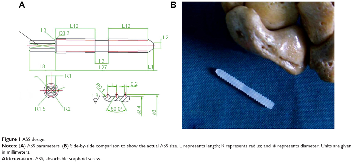 | Figure 1 ASS design. |
Equipment and experimental tools
A thread tapper and drill were purchased from Kanghui Medical Device Company (Kunming, People’s Republic of China). Point reduction forceps were purchased from Kouan Medical Device Co., Ltd. (Chongqing, People’s Republic of China). K-wires were provided by the Department of Orthopaedic Surgery, Southwest Hospital of the Third Military Medical University. The computerized tomographic instrument used was a SOMATOM Sensation 16 (Siemens, Berlin, Germany). An MTS 880 material testing system was purchased from MTS Systems Corp. (Eden Prairie, MN, USA). Other tools were provided by the central laboratory of Southwest Hospital of the Third Military Medical University.
Human hand samples
Fresh human hands were removed from eleven adult corpses (all males, aged 22–45 years, average 28.5), which were obtained from the Southwest Hospital of the Third Military Medical University within 24 hours postmortem by cutting at proximally 20 cm from the wrist crease. Twenty samples were obtained, eleven left hands and nine right hands. All of the 20 samples were equally divided into ASS group (with five left hands and five right hands) and K-wire group (with six left hands and four right hands). All samples were free of any pathological conditions based on the patients’ medical histories. The present study was approved by the ethics committee of Kunming General Hospital, Chengdu Military Region, Chengdu, China, informed patient consent was not deemed necessary for this study as specimens were obtained post-mortem.
Surgical procedures for fixation
In this study, we used the same technique to perform the fracture reduction between the ASS and K-wire groups.
Scaphoid fixation using an ASS
This group included ten specimens. We used a dorsal approach to make a 5 cm S-shaped incision on the nasopharyngeal fossa near the wrist. Tissues were separated layer-by-layer, and the dorsal cutaneous branch of the radial nerve was well protected. We pulled open the hallucis longus tendon, the hallucis brevis, and the abductor hallucis longus tendon to each side with retractors (Figure 2A). The superficial wrist joint capsule of the radioscaphoid joint was cut open and the navicular was exposed, while carefully protecting the scapholunate ligament.20,21 Scaphoid waist fractures were made with an osteotome and fixed using Weber pliers. A drill hole was made at the distal scaphoid tubercle with a 2.5 mm drill bit throughout the marrow of the scaphoid bone. A 2.7 mm tapper was used to screw the ASS into the bone (Figure 2B). After this, the Weber pliers were removed and the joint capsule was sutured. After subcutaneous sutures were used, the samples were marked for subsequent testing.
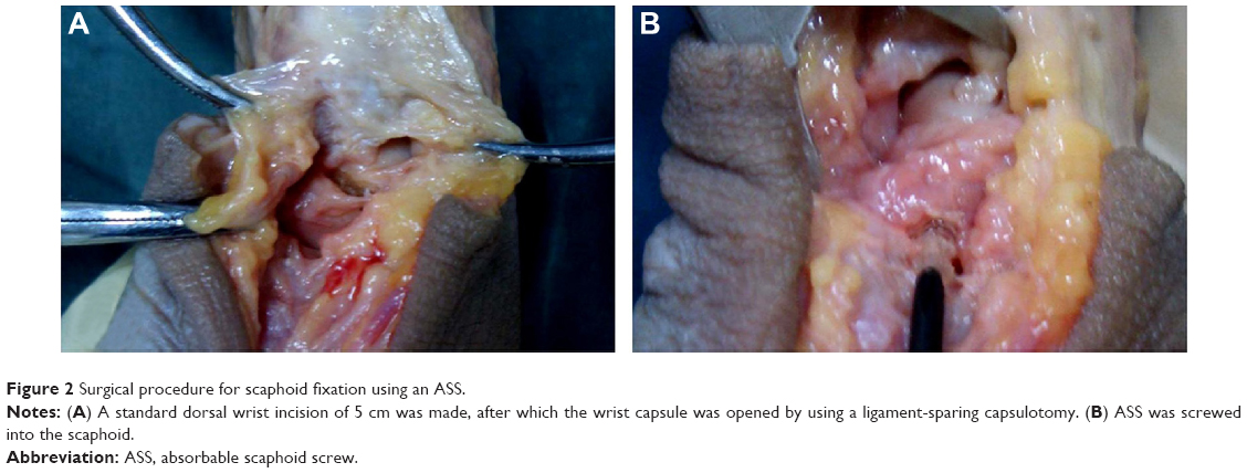 | Figure 2 Surgical procedure for scaphoid fixation using an ASS. |
Scaphoid fixation using K-wires
This group also included ten specimens. As with the ASS group, a standard dorsal approach was used. A 5 cm S-shaped incision was made near the nasopharyngeal fossa of the wrist. Tissue was separated layer-by-layer, and the dorsal cutaneous branch of the radial nerve was well protected. The hallucis longus tendon was raised and retracted in an ulnar direction to expose. The hallucis brevis and the abductor hallucis longus tendon were separated to two sides with retractors. The superficial wrist joint capsule of the radioscaphoid joint was cut open and the navicular was exposed, while carefully protecting the scapholunate ligament. Using an osteotome, a fracture was made through the waist of the scaphoid. We maintained the reduction with pointed reduction clamps. The distal scaphoid tubercle was drilled with a 2.5 mm K-wire throughout the marrow of the scaphoid bone. The K-wire should not penetrate into the radius or ulna. Any excess K-wire was snapped with a vise. The Weber pliers were removed, and the joint capsule was sutured. Subcutaneous sutures were then used for wound closure.
Fracture gap displacement measurements before and after fatigue testing
The same methods were used for both groups to measure fracture gap displacement. Data derived from computerized tomography (CT) scanning were transferred to a computer. Mimics software was used to determine fracture gap three-dimensional displacements (Figure 3). For each sample, fracture gap displacement was measured in the sagittal, coronal, and horizontal planes. For each plane, fracture gap displacement was measured at three points. The average of these three points and three planes was determined to represent fracture gap displacement. The samples were formalin fixed after the mechanical testing.
 | Figure 3 CT imaging of a scaphoid fixed with ASS with fracture gap measurement. |
Fatigue testing using a moving target simulator
Specimen preservation
Fresh wrist samples were kept in a −30°C low temperature medical refrigerator. At 12 hours before testing, frozen hands were removed from the refrigerator and thawed at room temperature. Because fatigue testing would take considerable time, in order to prevent specimen corruption, specimens were kept on ice in two 10 L foam insulation boxes. After an experiment, a specimen was returned to the −30°C low temperature medical freezer.
Specimen embedding
Muscle tissues proximal to the radius and ulna at the wrist were completely removed. An 8–10 cm length of exposed radius and ulna diaphyses were used as a mechanical terminal and embedded with denture powder. Denture powder (40 g) and 20 mL of water were mixed well in a 7 cm ×5 cm ×8 cm plastic box, after which the proximal radius and ulna were inserted into the embedding medium. After vertical suspension for 0.5 hour, the proximal specimen was embedded as a 7 cm ×5 cm ×8 cm fixed end.
Fatigue test model setup
A 3.5 mm twist drill was used to drill a hole on the base of the third metacarpal. A board and 8 cm screw were installed, after which the screws were tightened to conform to the mechanical output terminal.
Fatigue experiments
A sample was fixed on the MTS material testing system to test for palmar flexion and dorsal extension of the wrist joint. Range of motion of the wrist was set between 5° of flexion and 25° of extension.22–24 The frequency used was 0.7 Hz. Each hand was subjected to testing 2,000 times.25,26 Fracture gap displacement was then measured using CT scanning (Figures 4 and 5).
 | Figure 4 CT scanning to measure fracture gap displacement after fatigue testing. |
 | Figure 5 3D palm reconstruction image after fatigue testing. |
Biomechanical tests of tensile strength and flexural strength
Scaphoid dissection
Wrist samples were removed from the −30°C low temperature medical refrigerator at 12 hours before testing and thawed at room temperature. The scaphoids with an AAS and K-wires were carefully dissected out.
Tensile testing
After removing the scaphoid, two 2.0 mm K-wires were implanted in the navicular bones at a distance of 6 mm from each end. The two K-wires were parallel to the scaphoid fracture plane. The two ends were placed on a wire saw to act as mechanical traction terminals. Vertical tension generated by an RGT-5A computer-controlled electronic universal testing machine was transmitted to the scaphoid fracture surface by the wire saw connection. Results were recorded when a screw broke or a dislocation occurred for the ASS group or a fracture line widened by 1 mm in the K-wire group.
Bending test
After tensile testing, the scaphoids were refixed, and the new AAS and K-wire were placed. Both ends of a scaphoid were sandpapered as force supporting points. Then, a three-point bending test was applied to a sample. Navicular bones were applied directly in the RGT-5A computer-controlled electronic universal testing machine for these tests. Results were recorded when a screw broke or there was scaphoid sliding.
Statistical analysis
Statistical comparisons of the results for fracture gap displacement, tensile strength, and flexural strength between the ASS and K-wire groups were made by Student’s t-test.
Results
Fractured scaphoid fixation with an ASS or K-wire
Fixation with an ASS was an easy procedure that took ~10 minutes. A fractured scaphoid bone could be fixed with an ASS to restore its anatomical positions, which is good for healing in alignment. ASS screw heads did not extend into the scaphoid radial articular surface. Two ASS screw tail residues of 2–3 mm were difficult to screw into the ten samples used. For one case, a screw slipped into the slot, and a new ASS was replaced for retightening. The reduction procedure was easy. Fractured bones were fixed with a natural position and alignment. A K-wire end reissued a small part into the radiocarpal joint.
Fracture gap displacements in the ASS and K-wire groups
It was important to determine whether the mechanical properties of our ASS would meet the necessary requirements in order to evaluate its potential for clinical applications. Thus, we compared fracture gap displacements between the ASS and K-wire groups. Before fatigue testing, as measured by CT scanning, there were no significant differences between the ASS and K-wire groups for fracture gap displacements (Table 1). After fatigue testing, fracture gap displacements increased in both groups as measured by CT. Interestingly, fracture gap displacement in the K-wire group was seven times greater than that in the ASS group. These data suggested that fixation with our ASS was more stable than with a K-wire under mechanical stress.
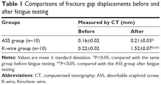 | Table 1 Comparisons of fracture gap displacements before and after fatigue testing |
Tensile and flexural strengths in the ASS and K-wire groups
To further test the biomechanical properties of our ASS, tensile and flexural strengths were measured in the ASS and K-wire groups. Biomechanical tests were performed after fatigue testing. As shown in Table 2, the ASS provided a tensile strength of 0.95±0.02 MPa, while a K-wire gave a tensile strength of 0.63±0.02 MPa (P<0.05). Flexural strength in the ASS group was 2.71±0.2 MPa and was 2.5±0.52 MPa in the K-wire group (P>0.05). The results of biomechanical tests suggested that our ASS could provide more stable mechanical support after fixation than a K-wire, which would be beneficial for fracture healing.
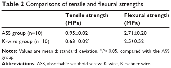 | Table 2 Comparisons of tensile and flexural strengths |
Discussion
We used CT scanning to measure fracture gap displacement as CT imaging permitted three-dimensional measurements. Due to the preciousness of human samples, all the samples used for tensile strength measurement went through biomechanical fatigue test. It is possible that the fatigue testing weakened the fixation screw/wire or its attachment with the bone in which case the tensile testing underestimates the true tensile strength.27–29 Both ASS and K-wire groups would likely be influenced to the same degree and thus should not influence the outcome of a comparison. Tensile testing after fatigue testing may also be more realistic in real-life conditions.30 In any case, the scaphoid screw (SS) outperformed the K-wire in tensile testing.
It was easy to perform at the distal scaphoid tubercle during fixation with our ASS. Because the screws did not go through the radiocarpal joint, this reduced damage to the articular surface. Our ASS had a conical tail and a screw head with 0.3 mm diameter. This structure may have increased its resistance. Our ASS was designed according to the anatomy of the normal human; therefore, this ASS method fits the anatomy of human. Moreover, ASS cannot cause the complications by using the K-wires method and could be effective in long-standing nonunion scaphoid fracture, which was better compared to the K-wires and Herbert screw methods. It also increased the difficulty of screwing the 2–3 mm tail residues into bone and caused slipping. To resolve this problem, our ASS can be redesigned to have deeper cross grooves, which should provide greater mechanical strength.31
The purpose of the fatigue testing was to compare the ASS and K-wire groups by simulating wrist flexion and extension activities after scaphoid fracture fixation. Based on the results of the K-wire group, the fracture gap began to increase after flexion circles and wrist extension. Therefore, plaster is often used in clinics to prevent movement after fixing a scaphoid fracture with K-wires. However, data for our ASS group showed that fracture gap displacement changed very little after wrist flexion and extension for 2,000 times. If ASS scaphoid fracture fixation was applied clinically, doctors may consider using a bandage to allow movement at an early healing stage.
The goal of developing the ASS was to explore for a more common, simple surgical operation method to be used for scaphoid fracture treatment. The advantages of ASS include fixation without plaster and no need for a second surgery to remove internal fixation devices, such as a Herbert screw. Additionally, it is easy to screw a bolt at the distal scaphoid tubercle during ASS fixation. Because these screws do not go through the radiocarpal joint, this reduces the damage to the articular surface. As a preliminary study, we only compared the ASS with the most basic fixation method, that is, K-wire. This made this study simple; however, comparison between ASS and other scaphoid screws will be performed in the subsequent studies.
The scaphoid assumes a boat conformation. Its articular facet is S-shaped, right in the connection site between two carpals. It has been reported that the angles of carpals in a proximal row, particularly the scaphoid, may change significantly when wrist joints are flexed and extended.32 When there is a fracture in the scaphoid, the motion of a wrist joint is primarily via the fracture line, which renders the fractured end to become vulnerable to shear stress. Therefore, due to the unstable status, a scaphoid fracture is considered an unstable fracture. Therefore, it is quite important to reestablish stability after scaphoid fracture. We design this ASS to fit the anatomic status of the scaphoid. The procedure for internal fixation at the scaphoid with the ASS was simple with less damage to the scaphoid compared to the K-wire method. The present study also showed that the ASS performed better than the K-wire at stabilizing the fracture during mechanical testing, making it a better choice than the K-wire for fracture fixation. Moreover, our designed screw also included a few advantages, including convenience for surgical placement, fracture reduction, and less cost, compared to the other methods for the clinical application. Therefore, our ASS is a feasible fixation material for the scaphoid.
Although we have received some of the significant results about the designed ASS methods, there were also a few limitations. After tensile testing, the scaphoids were refixed, and the new AAS and K-wire were placed. However, the previous fracture gap was not better maintained. This would compromise the integrity of the testing as the screw/wire hole would likely be distorted from tensile testing. In the further study, we would improve the processes for maintaining fracture gap.
Conclusion
In conclusion, our ASS was designed based on the anatomical features of the human scaphoid. Using this ASS for scaphoid fixation after fracture simplified the surgical procedures required and reduced damage to the scaphoid. This ASS had sufficient biomechanical strength to support the scaphoid during fracture healing.
Disclosure
The authors report no conflicts of interest in this work.
References
Patel D, Dean C, Baker RJ. The hand in sports: an update on the clinical anatomy and physical examination. Prim Care. 2005;32(1):71–89. | ||
Eathorne SW. The wrist: clinical anatomy and physical examination – an update. Prim Care. 2005;32(1):17–33. | ||
Cooney WP, Dobyns JH, Linscheid RL. Fractures of the scaphoid: a rational approach to management. Clin Orthop Relat Res. 1980;(149):90–97. | ||
Ram AN, Chung KC. Evidence-based management of acute nondis-placed scaphoid waist fractures. J Hand Surg Am. 2009;34(4):735–738. | ||
Buijze GA, Ochtman L, Ring D. Management of scaphoid nonunion. J Hand Surg Am. 2012;37(5):1095–1100. | ||
Hunter D. Diagnosis and management of scaphoid fractures: a literature review. Emerg Nurse. 2005;13(7):22–26. | ||
Matsuki H, Ishikawa J, Iwasaki N, Uchiyama S, Minami A, Kato H. Non-vascularized bone graft with Herbert-type screw fixation for proximal pole scaphoid nonunion. J Orthop Sci. 2011;16(6):749–755. | ||
Drac P, Manak P, Labonek I, Benýsek V. Percutaneous osteosynthesis of scaphoid fractures: preliminary results. Acta Chir Orthop Traumatol Cech. 2004;71(3):165–170. | ||
Ezquerro F, Jimenez S, Perez A, Prado M, de Diego G, Simón A. The influence of wire positioning upon the initial stability of scaphoid fractures fixed using Kirschner wires: a finite element study. Med Eng Phys. 2007;29(6):652–660. | ||
Zoubos AB, Triantafyllopoulos IK, Babis GC, Soucacos PN. A modified Matti-Russe technique for the treatment of scaphoid waist non-union and pseudarthrosis. Med Sci Monit. 2011;17(2):MT7–MT12. | ||
Soliman MM, Zaki AA, EI Gazaerly HM, Shemmrani AA, Sorour Ael L. Clinical and radiographic evaluation of copolymerized polylactic/polyglycolic acids as a bone filler in combination with a cellular dermal matrix graft aound immediate implants. Int J Health Sci. 2014;8(4):381–392. | ||
Hughes TB. Bioabsorbable implants in the treatment of hand fractures: an update. Clin Orthop Relat Res. 2006;445:169–174. | ||
Hollinger JO. Preliminary report on the osteogenic potential of a biodegradable copolymer of polyactide (PLA) and polyglycolide (PGA). J Biomed Mater Res. 1983;17(1):71–82. | ||
Majola A, Vainionpaa S, Vihtonen K, et al. Absorption, biocompatibility, and fixation properties of polylactic acid in bone tissue: an experimental study in rats. Clin Orthop Relat Res. 1991;268:260–269. | ||
Bostman O, Vainionpaa S, Hirvensalo E, et al. Biodegradable internal fixation for malleolar fractures. A prospective randomised trial. J Bone Joint Surg Br. 1987;69(4):615–619. | ||
Rokkanen P, Bostman O, Vainionpaa S, et al. Biodegradable implants in fracture fixation: early results of treatment of fractures of the ankle. Lancet. 1985;1(8443):1422–1424. | ||
Kong WY, Xu YQ, Wang YF, Chen SC, Liu ZL, Li XG. Anatomic measurement of wrist scaphoid and its clinical significance. Chin J Traumatol. 2009;12(1):41–44. | ||
Bedi A, Jebson PJ, Hayden RJ, Jacobson JA, Martus JE. Internal fixation of acute, nondisplaced scaphoid waist fractures via a limited dorsal approach: an assessment of radiographic and functional outcomes. J Hand Surg Am. 2007;32(3):326–333. | ||
Jones NF, Brown EE, Mostofi A, Vogelin E, Urist MR. Healing of a scaphoid nonunion using human bone morphogenetic protein. J Hard Surg. 2005;30:528–533. | ||
Barber FA, Herbert MA. Meniscal repair devices. Arthroscopy. 2000;16(6):613–618. | ||
Moran SL, Ford KS, Wulf CA, Cooney WP. Outcomes of dorsal capsulodesis and tenodesis for treatment of scapholunate instability. J Hand Surg Am. 2006;31(9):1438–1446. | ||
Shin AY, Horton T, Bishop AT. Acute coronal plane scaphoid fracture and scapholunate dissociation from an axial load: a case report. J Hand Surg Am. 2005;30(2):366–372. | ||
Papadonikolakis A, Shen J, Garrett JP, Davis SM, Ruch DS. The effect of increasing distraction on digital motion after external fixation of the wrist. J Hand Surg Am. 2005;30(4):773–779. | ||
Miura T, Firoozbakhsh K, Cheema T, Moneim MS, Edmunds M, Meltzer S. Dynamic effects of joint-leveling procedure on pressure at the distal radioulnar joint. J Hand Surg Am. 2005;30(4):711–718. | ||
Takase K, Yamamoto K. Mechanical strength and optimal site of placement of a threaded bone screw assessed on the basis of the screw breakage for non-union of the scaphoid: a biomechanical study. Hand Surg. 2005;10(2–3):225–230. | ||
Kong W, Xu Y, Wang Y, Chen B, Xu Z, Li R. Development and biomechanical study of Ni-Ti shape memory alloys scaphoid arc nail. Zhongguo Xiu Fu Chong Jian Wai Ke Za Zhi. 2008;22(1):48–52. | ||
Atthakomol P, Wangjiraphan N, Krudtong S, et al. Pull-out strength of 0/30 Kirschner wire syringe external fixators with and without polymer augmentation: a biomechanical study. J Med Assoc Thai. 2015;98(1):82–87. | ||
Koistinen AP, Korhonen H, Kroger H, Lappalainen R. Interfacial sliding properties of bone screw materials and their effect on screw fixation strength. J Appl Biomater Funct Mater. 2014;12(2):90–96. | ||
Sawyer GA, Anderson BC, Paller D, Heard WM, Fadale PD. Effect of interference screw fixation on ACL graft tensile strength. J Knee Surg. 2013;26(3):155–159. | ||
Hosseinian E, Pierron ON. Quantitative in situ TEM tensile fatigue testing on nanocrystalline metallic ultrathin films. Nanoscale. 2013;5(24):12532–12541. | ||
Sobieraj MC, Kurtz SM, Wang A, Manley MM, Rimnac CM. Notched stress-strain behavior of a conventional and a sequentially annealed highly crosslinked UHMWPE. Biomaterials. 2008;29(35):4575–4583. | ||
Lewis OJ. Joint remodelling and the evolution of the human hand. J Anat. 1977;123(1):157–201. |
 © 2016 The Author(s). This work is published and licensed by Dove Medical Press Limited. The
full terms of this license are available at https://www.dovepress.com/terms
and incorporate the Creative Commons Attribution
- Non Commercial (unported, 3.0) License.
By accessing the work you hereby accept the Terms. Non-commercial uses of the work are permitted
without any further permission from Dove Medical Press Limited, provided the work is properly
attributed. For permission for commercial use of this work, please see paragraphs 4.2 and 5 of our Terms.
© 2016 The Author(s). This work is published and licensed by Dove Medical Press Limited. The
full terms of this license are available at https://www.dovepress.com/terms
and incorporate the Creative Commons Attribution
- Non Commercial (unported, 3.0) License.
By accessing the work you hereby accept the Terms. Non-commercial uses of the work are permitted
without any further permission from Dove Medical Press Limited, provided the work is properly
attributed. For permission for commercial use of this work, please see paragraphs 4.2 and 5 of our Terms.