")
Back to Journals » Nanotechnology, Science and Applications » Volume 16
Silver Shell Thickness-Dependent Conductivity of Coatings Based on Ni@Ag Core@shell Nanoparticles
Authors Pajor-Świerzy A, Kozak K, Duraczyńska D, Wiertel-Pochopień A, Zawała J, Szczepanowicz K
Received 14 August 2023
Accepted for publication 19 December 2023
Published 27 December 2023 Volume 2023:16 Pages 73—84
DOI https://doi.org/10.2147/NSA.S435432
Checked for plagiarism Yes
Review by Single anonymous peer review
Peer reviewer comments 2
Editor who approved publication: Professor Kattesh Katti
Anna Pajor-Świerzy, Katarzyna Kozak, Dorota Duraczyńska, Agata Wiertel-Pochopień, Jan Zawała, Krzysztof Szczepanowicz
Jerzy Haber Institute of Catalysis and Surface Chemistry, Polish Academy of Sciences, Kraków, Poland
Correspondence: Anna Pajor-Świerzy, Jerzy Haber Institute of Catalysis and Surface Chemistry, Polish Academy of Sciences, Kraków, Poland, Email [email protected]
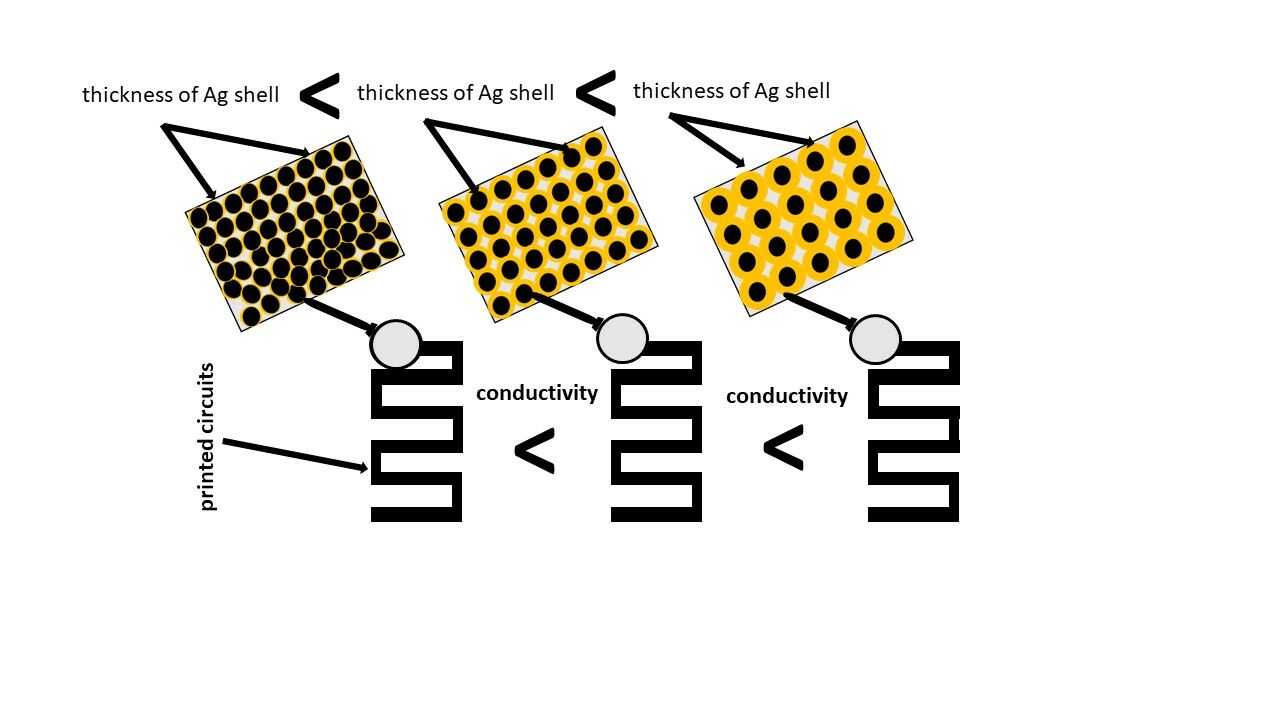
Introductions: Ink based on metallic nanoparticles has been widely used so far for the fabrication of electronic circuits and devices using printing technology. This study aimed at the analysis of the effect of the silver shell thickness of nickel@silver core@shell (Ni@Ag) nanoparticles (NPs) on the fabrication and conductive properties of deposited coatings.
Methods: The process of the synthesis of Ni@Ag NPs with various silver shell thicknesses was developed. The physicochemical properties (size, stability against aggregation process) of synthesized Ni@Ag nanoparticles were analyzed. The films based on ink containing Ni@Ag NPs with different silver shell thicknesses were fabricated and sintered in a temperature range of 120– 300 °C and at times from 15 to 90 min. The dependence of their conductive properties on the applied temperature and time as well as silver shell thickness was evaluated.
Results: Ni NPs were coated with 10, 20, 30, 35, 45, and 55 nm silver shell thickness. The resistivity of coatings based on obtained NPs depends on the thickness of the Ag shell and the sintering temperature. After sintering at 300 °C, the highest decrease in its value (at an optimal sintering time of 60 min) from about 100 μΩ·cm to 9 μΩ·cm was observed when the thickness of the shell increased from 10 to 55 nm. At the lowest sintering temperature (120 °C) the highest conductivity (about 50% of that for bulk nickel) was obtained for films based on Ni@Ag NPs with 45 and 55 nm of the silver shell thickness.
Discussions: The analysis of the resistivity of the sintered films showed that higher conductivity was obtained for the coatings formed from Ni@Ag NPs with the thicker Ag shell; moreover, thicker shells allowed a lowering of sintering temperature due to higher conductivity and a lower melting point of silver in comparison to nickel NPs.
Keywords: core@shell nanoparticles, the thickness of the silver shell, thermal sintering, conductive properties, metallic coatings
Graphical Abstract:
Introduction
Traditional methods of fabrication of electronic devices such as photolithography, vacuum deposition, or electroless plating processes are multi-stage, require high-cost equipment, and form large amounts of waste. As an alternative method of manufacturing conductive circuits, eco-friendly, simple, and highly productive printing technology has been proposed. Printed electronics as a low-cost and environment-friendly research and industrial field is promising for large-scale fabrication of conductive patterns and devices.1–4
The process of the formation of conductive ink is the most important stage of printing electronic technology to achieve conductive patterns with high quality and electrical conductivity.5,6 The main component of conductive ink is a functional material, usually highly conductive micro- or nano-grade metal particles.7,8 Currently, silver is the most widely used material for utilization in conductive inks due to its high conductivity and stability against the oxidation process. However, due to the presence of insulating organic material, which is necessary for the NPs array stability, the conductivities of the as-deposited ink based on nanoparticles are generally poor. Therefore, a post-deposition treatment is needed to enhance them, which is generally achieved by applying heat, usually in a hot air oven or hot plate.9,10 This sintering phenomenon is usually attributed to the reduced melting point of NPs and the high self-diffusion coefficient of their atoms.11 Under optimal conditions, the conductive properties of coatings formed from ink based on Ag NPs are comparable with the conductivity of bulk metal.2,3,12 However, due to the high cost of silver, a major challenge in this field is to replace them with cheaper ones, such as nickel or copper.4 In addition, materials based on Ag NPs show poor mechanical stability, which can limit their application in the production of electronic devices, while the ones composed of Ni NPs are more resistant to failure or plastic deformation.13 The disadvantage of such non-noble metallic nanoparticles like nickel and copper is a tendency to oxidize at ambient conditions, due to their low standard redox potential, which causes a decrease or loss of electrical conductivity of the printed pattern. Protection of Ni or Cu NPs can be obtained by coating the individual nanoparticles with a dense layer of capping agents, such as surfactants, polymers, alkanethiols, and long-chain carboxylic acids.14–16 However, those methods only minimize the oxidation process of NPs but do not provide their long-term stability. In this context, the best approach is the formation of a shell of a noble metal on the surface of oxidizable metallic nanoparticles, which results in the obtaining of core@shell bimetallic NPs. This process is usually performed by using a displacement (transmetalation) reaction, which is based on the difference in the redox potential of two metals (core and shell), where the surface of the core nanoparticles acts as a reducing agent for the noble metal deposited on their surface.17–20
In the last year, a growing interest in the fabrication of conductive coatings or patterns formed from ink based on Cu@Ag and Ni@Ag NPs as the promising pathways for the fabrication of printed electronic devices has been observed. Jing et al21 prepared a conductive film from a paste based on Ni@Ag NPs with an average size of 104 nm after sintering at 650 °C. The obtained coating had a sheet resistance of 11 mΩ/□, which is superior to that of the nickel pastes, and close to that of the silver pastes. The aqueous dispersion of stable Cu@Ag core@shell NPs as conductive and decorative inks for printing metallic patterns on various substrates was used.22 Gang et al23 prepared a stable Cu@Ag-based ink that was successfully screen-printed onto a flexible polyimide (PI) substrate. They observed a decrease in the resistivity of the Cu@Ag pattern about 15 times in comparison to bulk copper when the sintering temperature was raised to 290 °C.
he ability to control the shell thickness of metallic core@shell NPs can open up attractive opportunities for the fabrication of a broad range of new materials with tunable properties. Therefore, the studies of this subject are important from scientific as well as industrial point of view. Xie et al24 the dependence of the thickness of the platinum shell of Pd@Pt nanostructures on their catalytic activity toward oxygen reduction detection was studied. They observed that nanocubes of palladium coated with 2–3 platinum layers showed higher specific activity and durability toward the oxygen reduction reaction than the one containing only one Pt layer. A significant improvement of photovoltaic parameters of solar cells based on Ag@Au NPs with increasing thickness of gold shell was observed by Wali et al.25 The effect of the shell thickness of Cu@Ag NPs on their sintering process was also investigated by using the atomistic sintering simulation method. Besides experimental works, theoretical studies on the dependence of properties of core@shell NPs on the thickness of their shell were performed. The effect of the shell thickness of Cu@Ag NPs on their sintering process was investigated by using the atomistic sintering simulation method. It was noticed that thinner silver shells prevent the contribution of the plastic deformation mechanism to sintering and the proportion of amorphous Ag atoms at the sintering neck increases.26 Sarkar et al27 studied the dependence of the tensile properties of crystals of Cu@Ag core@shell nanowire on the thickness of Ag shell using molecular dynamics simulations. The highest yield strength for nanowires with a shell thickness of 2 nm and a core diameter of 10 nm was observed, while the Cu@Ag nanowires with a thickness of the shell of 10 nm and 8 nm with the same core diameter showed the highest ultimate tensile strength and the highest Young’s modulus, respectively.
In the context of the potential application of metallic nanoparticles in various industrial areas, an important issue is their impact on human health and the environment. It is known that nanoparticles due to their small size can enter the human body through the lung, intestinal tract, or skin, and can be toxic to the brain, causing lung inflammation or heart disease.28 Metallic nanoparticles can enter the environment during the fabrication of materials based on them, their application, or following the disposal of products containing nanoparticles.29 Moore30 as well as Hund-Rinke and Simon31 suggested that NPs have the potential to cause harmful effects on biota by the formation of reactive oxygen species that could affect biological structures. However, the toxicity of nanoparticles depends on many factors such as their size, composition, surface functionality, crystallinity, or aggregation degree.
In the present work, we mainly focused on the analysis of the dependence of the formation process as well as the resistivity of the coatings based on Ni@Ag NPs on the thickness of their silver shell after the thermal sintering process to obtain highly conductive metallic films. We observed that the values of resistivities depend on the thickness of the silver shell as well as the sintering temperature. The highest conductivity was obtained for the coatings formed from Ni@Ag NPs with the thickness of Ag shell of 35 nm and 45 nm after the sintering process at 180 and 120 °C, respectively. The improvement of conductivity of coatings by using Ni@Ag NPs with thicker silver shells, to the best of our knowledge, is reported for the first time and may represent a new approach for obtaining printed electronics.
Materials and Methods
Materials
Nickel sulfate hexahydrate (NiSO4·6H2O), sodium borohydride (NaBH4), sodium carboxymethyl cellulose (MW 90000, NaCMC), silver nitrate (AgNO3), citric acid (CA), and aminomethyl propanol (AMP) were supplied from Sigma-Aldrich (Poznań, Poland). A wetting agent, Surfynol PSA 336 (acetylenic-based formulated surfactant), was purchased from Evonik (Essen, Germany). Distilled water was used for the preparation of all solutions.
Fabrication of Conductive Coatings Based on Ni@Ag NPs
The process of preparation of metallic coatings involved three stages: (1) synthesis of Ni@Ag NPs; (2) ink formulation; (3) preparation of coatings and their sintering.
Synthesis of Ni@Ag NPs
Ni@Ag NPs were obtained by the method developed in our lab and detailed presented in our previous papers.32–34 The process consists of two steps: (1) synthesis of an aqueous dispersion of Ni NPs, (2) silver shell formation.
In the first step, 30 mL of 0.5% of stabilizer (NaCMC), 12 mL of 5.2% of Ni NPs precursor (NiSO4), 12 mL of 1.4% of citric acid, and 5 mL of 80% of AMP (complexing agents), were mixed. Then, a peristaltic pump was used to inject 30 mL (2 mL/min) of an aqueous solution of NaBH4 (0.2%), as the reducing agent, into the reaction mixture, which was followed by stirring at 850 rpm for 60 min. As a result of this process, Ni NPs were synthesized.
In the second step, the silver shell is formed by the transmetalation (displacement) reaction resulting in the formation of Ni@Ag NPs. Silver shell precursor ie aqueous solutions of AgNO3, at concentrations ranging from 0.02 to 0.1 M and a constant volume of 45 mL, were added to the freshly synthesized dispersion of Ni NPs. The synthesis was performed for 60 min at room temperature while stirring at 850 rpm. Then, the obtained dispersions of Ni@Ag NPs were washed by centrifugation/redispersion process (two times, 7000 rpm, 20 min) with distilled water, where an excess of stabilizer and other additives was removed.
Ink Formulation
To prepare inks, the dispersions of Ni@Ag NPs were concentrated to 25 wt% and their wetting properties were optimized by using Surfynol PSA 336 at a concentration of 0.025%. The obtained inks were homogenized by using an ultrasonic bath for 30 min at 20 kHz.
Preparation of Coatings and Their Sintering
The ink formulation was deposited on glass substrates by bar coating with the use of K-Hand Coater (Kontech, Łódź, Poland).35 The deposited ink coatings were dried on a hot plate at 80 °C for 15 min and finally sintered by heating (thermal sintering process) at elevated temperatures (120–300 °C).
Characterization Methods
The size of metallic nanoparticles (Ni and Ni@Ag NPs) was measured by the dynamic light scattering (DLS) method. The experiments were carried out using Zetasizer Nano Series (Malvern Instruments, Malvern, Worcestershire, UK) with a detection angle of 173° in optically homogeneous square polystyrene cells. Each value was obtained from the three runs with at least 20 measurements at 25 °C. The optical properties of the dispersions of Ni and Ni@Ag NPs were studied by UV–Vis spectrophotometry (UV-1800, Shimadzu, Kyoto, Japan). The morphological properties of the obtained nanoparticles and their coatings were analyzed by scanning high-resolution field emission scanning electron microscope (SEM, JEOL JSM-7500F) equipped with an energy-dispersive X-ray spectroscopy system (EDS-INCA PentaFETx3) enabling qualitative and quantitative information about the elemental composition and element location/distribution. The thicknesses of deposited films were measured by the EDXRF technique (FISCHERSCOPE X-RAY XDL 230, Worcestershire, UK). The values of sheet resistance of the sintered metallic coatings were measured using a 4-point probe technique (Milliohm Meter, Extech Instruments, Nashua, NH, USA). In this method, the values of sheet resistances were automatically measured for four equally spaced by manual contact of the collinear Calvin probes with the coated films, resulting in electrical contact.36 The values of resistivities of sintered films were calculated by multiplying the values of their sheet resistance by the thicknesses.6
Results and Discussion
The oxidation stability of metallic NPs is a crucial property for their practical applications for conductive coatings and printed electronics, therefore the main disadvantage of Ni NPs nanoparticles is a tendency to oxidize at ambient conditions. Protection of Ni NPs can be gained by the formation of a silver shell on the surface of nanoparticles, which results in obtaining core@shell Ni@Ag bimetallic NPs. In our previous works32–34 where the process of Ni@Ag NPs formation was presented in detail, it was found that the thickness of the Ag shell can be controlled by the appropriate selection of Ag precursor concentration, whose thickness increases with increasing concentration of Ag ions, respectively. Moreover, the minimal thickness of the Ag shell that improved long-term stability against oxidation for Ni NPs with size ~210 nm was ~20 nm.
In this paper, we focus on the analysis of the effect of the thicker silver shell on nickel@silver (core@shell) nanoparticles on the fabrication and conductivity of ink-based coatings. A scheme for preparation of conductive coatings composed of Ni@Ag NPs with different thicknesses of the silver shell is presented in Figure 1.
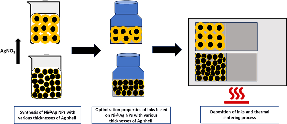 |
Figure 1 Scheme of the fabrication of the conductive coatings based on Ni@Ag NPs with various thicknesses of Ag shells. |
Firstly, Ni NPs were synthesized by reduction of Ni2+ in the complex with AMP and citric acid by NaBH4, in the presence of sodium carboxymethyl cellulose as a stabilizer. The synthesis was performed at the deficiency of the reducing agent, which is crucial for the stage of the formation of a silver shell. NaBH4 is fully consumed in the process of formation of Ni NPs, which prevents the reduction of Ag+ to Ag NPs, instead of their reduction on the surface of Ni NPs with the formation of a core@shell structure by transmetalation reaction. We found that the obtained Ni NPs with size 180 nm were not stable and oxidized in aqueous dispersion after a few hours of storage. To stabilize Ni NPs, a protective silver shell was formed on the surface of freshly prepared Ni NPs, which results in the formation of the core@shell structure. The Ni@Ag core@shell NPs were synthesized by the transmetalation process, in which on the surface of previously obtained Ni NPs, Ag ions are reduced due to the difference in the redox potential between those two metals. The DLS measurement (Figure 2A) indicates that the average sizes (as the value of three subsequent runs of the instrument) of obtained Ni@Ag NPs increase from about 180 to 280 nm with increasing concentration of silver salt (0.02–0.1M) added to Ni NPs. The delivery of a higher amount of AgNO3 as a source of silver ions for shell formation results in the fabrication of core@shell NPs with a thicker Ag layer on the surface of nickel NPs. It was shown in Figure 2B that as the concentration of Ag salt increased from 0.02 to 0.1 M, the thicknesses of the silver shell increased from 10 to 55 nm.
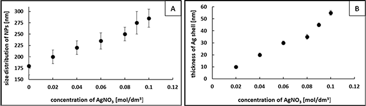 |
Figure 2 The dependence of the size of Ni@Ag NPs (A) and thickness of silver shell (B) on the concentration of AgNO¬3 in the reaction mixture. |
In Figure 3 the UV–vis spectra of the Ni and Ni@Ag NPs are presented. In the spectrum of bare Ni NPs, no peaks were observed, while the spectra of Ni@Ag core@shell NPs are characterized by distinct peaks with maximum bands at about 420 nm, which is typical for surface plasmons of silver with the size of nano.37 The UV–vis spectra of Ni@Ag NPs are much wider than those of Ag NPs. This phenomenon is similar to that obtained by the extended Mie theory for core@shell nanoparticles and indicates the formation of the core@shell structure.38,39 The dependence of the maximum absorbance intensity on the thickness of the silver shell in the spectra of Ni@Ag NPs was observed and as can be seen in Figure 3, their intensities increase with increasing thickness of the Ag shell, which suggests the formation of a thicker silver layer on the surface of Ni NPs. Similarly, Jackson et al38 observed an increasing magnitude of the extinction spectrum as more silver was deposited on the surface of the silica particles. Besides, they noticed shifting of the plasmon resonance to longer wavelengths with increasing thickness of the Ag shell. As can be seen in Figure 3, the absorption bands in the UV–vis spectra of Ni@Ag NPs with various thicknesses of silver shell were almost located at the same wavelengths. Titkov et al40 have observed a similar phenomenon for copper@silver NPs, with only a change in the absorption intensity ratios with increasing ratios of copper to silver.
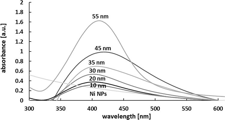 |
Figure 3 The UV-Vis spectra of the dispersion of the Ni and Ni@Ag NPs with various thicknesses of the silver shell (10–55 nm). |
The long-term stability of metallic nanoparticles against the aggregation process is important for the fabrication of printed conductive materials; therefore, the dependence of the size distribution of Ni@Ag NPs with thickness shells of 10, 20, 30, 35, 45, and 55 on the storage time was analyzed. The size distribution was investigated using the DLS technique. The synthesized dispersions of Ni@Ag NPs with various silver shells were weekly measured. As can be seen in Figure 4 the size of Ni@Ag NPs with thickness shells of 20, 35, and 45 nm almost did not change after 30 days of storage, which indicates their long-term stability regarding aggregation. In addition, in agreement with our previous work,32 the NPs with 10 nm silver shell thickness were not stable against oxidation over time, while thicker silver shell nanoparticles present superior stability against this process.
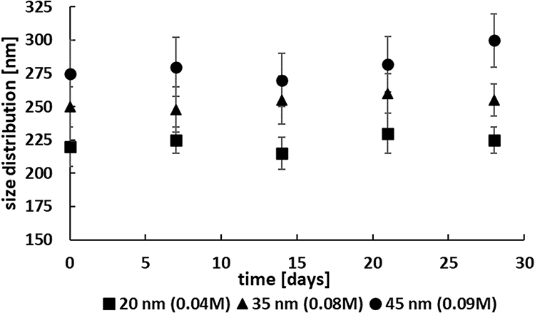 |
Figure 4 Example of the dependence of the size distribution of Ni@Ag NPs (applied for the fabrication of coatings with optimal conductivity) on the storage time. |
Ni@Ag NPs with 20 nm shell thickness were almost monodisperse with a spherical shape, as can be seen in the presented SEM image (Figure 5A). In the EDS spectrum of such NPs (Figure 5B), characteristic peaks of nickel and silver can be observed, which suggest the formation of core@shell structure.
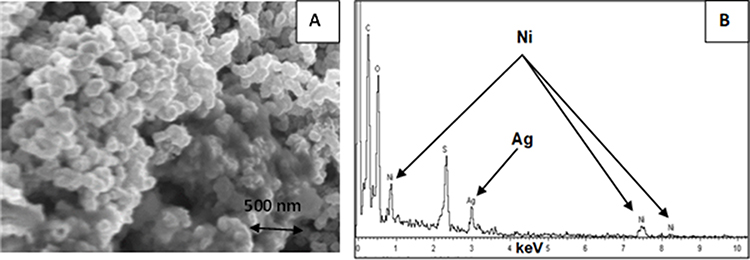 |
Figure 5 The characterization of the dispersion of the Ni@Ag NPs (thickness 20 nm of Ag shell): example of SEM image (A), EDS spectrum (B). |
To prepare inks, the formed dispersions of Ni@Ag NPs with various silver shell thicknesses were concentrated to 25 wt%, while their wetting properties were optimized by adding Surfynol PSA 336 at a concentration of 0.025%.34 The prepared inks were deposited on glass substrates by bar coating with the use of a K-Hand Coater. Then deposited coatings were dried on a hot plate at 80 °C for 15 min and finally sintered by heating at elevated temperatures (120–300 °C). The optimal sintering time was determined for each case and, as can be seen in Figure 6A, the resistivity of coatings, formed from Ni@Ag NPs with various thicknesses of Ag shell and sintered at various temperatures, decreased with sintering time up to 60 min, longer sintering time, even for 90 min, were characterized by almost the same conductive properties. In this context, the optimal sintering time – 60 min was selected for obtaining and characterization of metallic films. Figure 6B presents the dependence of values of resistivities of films formed from various Ni@Ag NPs on the sintering temperature at the optimal time (60 min). In addition to better showing the changes in resistivity of coatings formed from Ni@Ag NPs with thicker Ag shell (30–55 nm) Figure 6C is presented.
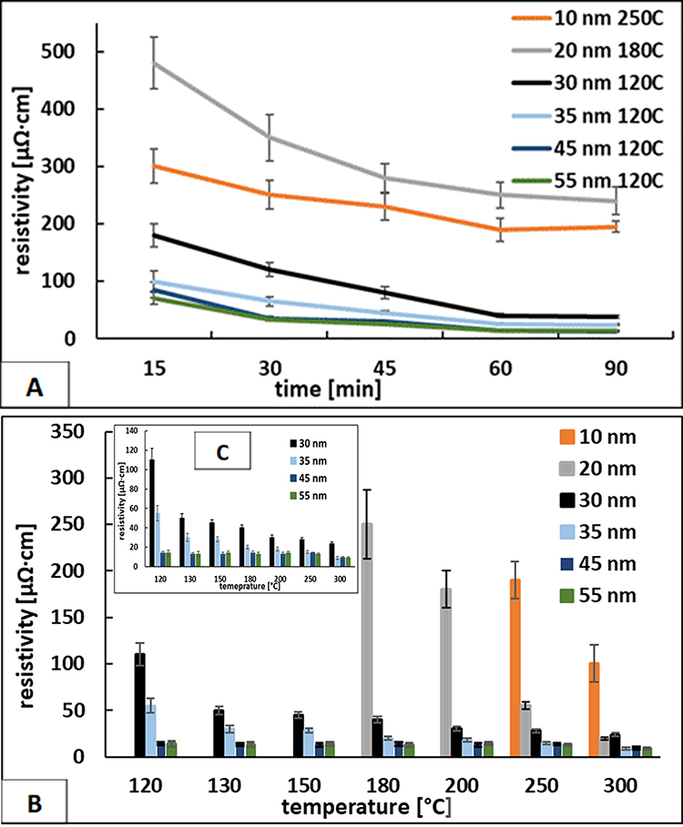 |
Figure 6 The dependence of the resistivity for coatings formed from Ni@Ag ink with various Ag shell thicknesses (10–55 nm) on (A) the sintering time (selected examples show conductive properties at lowest sintering temperature) and the temperature: (B) for Ag thickness shell from 10 to 55 nm; (C) for Ag thickness shell from 30 to 55 nm. |
In our previous work,33 we found out that the optimal conditions of the thermal sintering process of coatings based on Ni@Ag NPs at the size distribution of 220 nm (about 20 nm of Ag silver shell), which enables obtaining the best conductivity (about 48% of that for a bulk nickel), were temperature of 300 °C, and the value of resistivity of a metallic film with a thickness of about 2 µm was about 14 µΩ·cm. Using this concept, in the presented work, we started an analysis of the effect of Ag silver shell thickness on the conductivity of metallic coatings sintered at 300 °C. In Figure 6B can be noticed that the resistivity depends on the thickness of the Ag shell. The highest decrease in its value from about 100 µΩ·cm to 14 µΩ·cm was observed when the thickness of the shell increased from 10 to 20 nm. It is worth mentioning that Ni@Ag NPs with 10 nm Ag shell thickness were not stable against oxidation and the influence of oxides is clearly visible in conductive properties. Further growth of Ag shell thickness up to 55 nm affects the lowering of the resistivity to 9 µΩ·cm. In the context of the future application of conductive coatings in printed flexible electronics as well as from an economic point of view (lower temperature uses less energy), we additionally analyzed the resistivity of coatings formed from Ni@Ag ink with various Ag shell thicknesses at the lower sintering temperature (120–250 °C). It was noticed that coatings formed from ink based on Ni@Ag NPs with the thinnest silver shell (20 nm) started to be conductive after the sintering process at the temperature of 180 °C. The coatings based on nanoparticles with silver shell thickness from 30 to 55 nm showed conductive properties at a much lower sintering temperature of 120 °C. This is the result of the presence of a higher amount of metallic silver, which improves the conductivity of nickel as well as the formation of necks between NPs. In addition, bulk silver has a lower temperature (~961 °C) melting point than bulk nickel (~1451 °C), while their melting temperature at nano size is much lower.41,42 Therefore, Ni@Ag NPs with thicker Ag shells should be more easily merged at lower ranges of temperatures than the ones with thinner shells. Li et al43 noticed that during the sintering process of Cu@Ag NPs, the plastic deformation mechanism mainly occurred in the silver shell. Therefore, a thicker Ag shell increases the significance of the plastic mechanism, which can improve the thermal sintering process. The effect of silver shell thickness on the conductivity of metallic films is clearly visible for all sintering temperatures, and a thicker silver shell gives lower resistivity. For example, the resistivities of coatings sintered at 120 °C decrease from about 110 to 14 µΩ·cm with increasing silver shell thickness from 30 to 55 nm, respectively.
In Table 1 the dependence of calculated conductivity (in comparison to that for bulk nickel) of coatings based on Ni@Ag NPs on their shell thickness and sintering temperature is presented. As can be clearly seen, similar conductive properties at all applied sintering temperatures showed coatings containing core@shell NPs with silver shell thickness of 45 and 55 nm. Besides, we noticed that the sintered coatings based on such Ni@Ag NPs (with silver shell thickness of about 45 and 55 nm) showed similar conductive properties (50% of that for bulk nickel) as the one obtained in our previous research33 (with the conductivity of 48% in comparison to bulk nickel) for the thinner silver shell, but lower temperature (120 vs 300 °C) was needed to form that conductive coating. Generally, depending on the application that determines the sintering temperature, the optimal silver shell thickness should/could be chosen. For applications, where the temperature of sintering has to be as low as possible a thicker silver shell should be selected, while for applications where a higher temperature could be applied a thinner silver shell could be chosen.
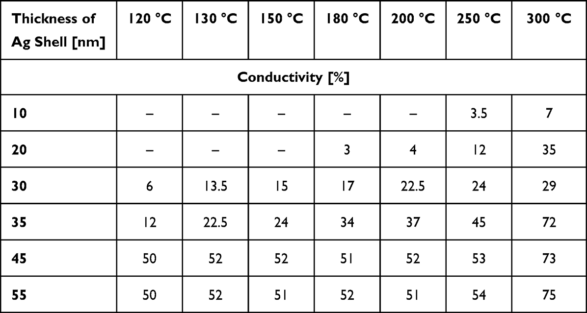 |
Table 1 The Dependence of the Conductivity [%] (in Comparison to That for Bulk Nickel) on the Thickness of the Silver Shell and Sintering Temperature at Optimal Sintering Time (60 min) |
Research on the dependence of conductive properties of coatings based on Ni@Ag NPs on the thickness of their shell has not been presented so far. However, the most similar conductive materials were obtained by Bai.43 In the performed study the resistivity of Ni, Cu, and Cu@Ni powders was analyzed and compared. After their sintering process at 200 °C the lowest value of resistivity of 4.6·10−6 Ω·m for Cu@Ni material was obtained and was slightly higher than the one achieved for coatings based on Ni@Ag NPs with a silver shell of 55 nm after sintering at lower temperature (120 °C). In addition, a comparison of the resistivity (9 µΩ·cm) of coatings containing Ni@Ag NPs with the thicker Ag shell (55 nm) after sintering at the highest temperature (300 °C) obtained in the presented work to the resistivity (25.5 µΩ·cm) of Cu@Ag patterns sintered at 290 °C reported in another study.44 As was noticed, the value achieved in our research was much lower.
The morphology of metallic coatings composed of the Ni@Ag NPs, with various Ag shell thicknesses, before and after the sintering process was examined by SEM. Examples of such coatings are presented in Figure 7. It is clearly seen that before sintering the Ni@Ag NPs were still not merged, and the continuous layer was not created while after the sintering, the connection between NPs is improved, which provides good conductivity of sintered coatings. Moreover, after sintering the single Ni@Ag nanoparticles are not present in the coatings, which should decrease the risk related to the use of nanomaterials and decrease the potential impact on the environment.
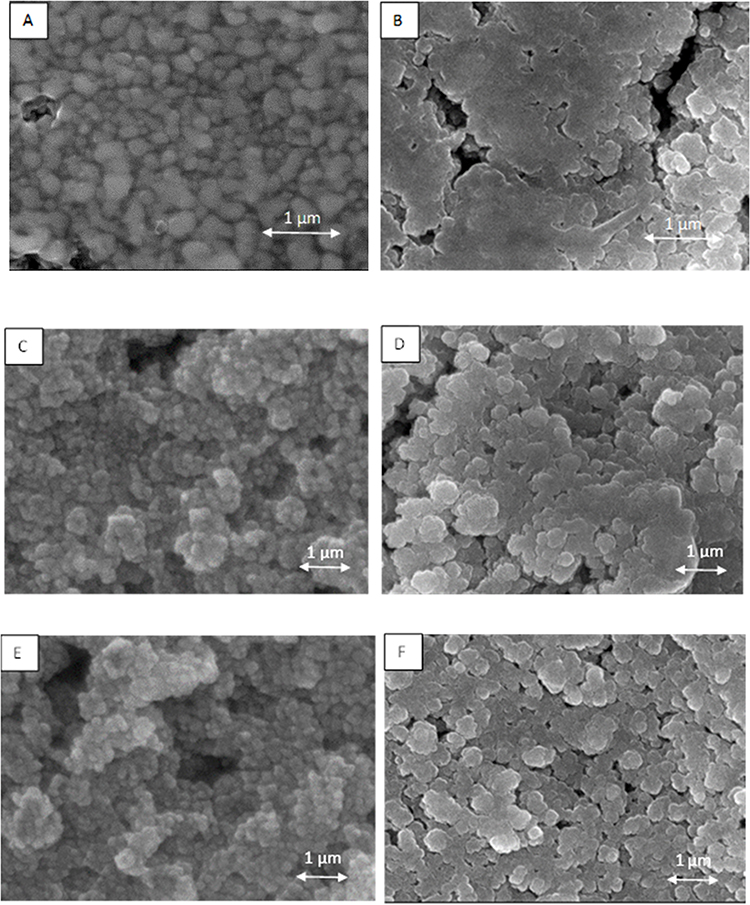 |
Figure 7 Examples of SEM images obtained for coatings based on Ni@Ag NPs with Ag thickness shell of 20 nm: (A) after drying (80 °C, 15 min), (B) after sintering at 300 °C; 35 nm: (C) after drying (80 °C, 15 min), (D) after sintering at 180 °C; and 45 nm: (E) after drying (80 °C, 15 min), (F) after sintering at 120 °C. |
Conclusions
In our work, we evaluated the effect of the thickness of the Ag shell on the surface of Ni NPs on the formation and conductive properties of coatings based on such Ni@Ag NPs. The temperature needed for the formation of conductive coatings by thermal sintering decreases; moreover, improvement of conductivity of metallic films can be achieved by using NPs with thicker Ag shells. Depending on the final application optimal thickness of the silver shell can be selected. For heat-sensitive substrates, where the temperature of sintering should be as low as possible, thicker silver shell will be optimal while for other applications where the higher temperature could be applied thinner silver shell should be chosen.
Acknowledgments
Thanks to Piotr Warszyński from Jerzy Haber Institute of Catalysis and Surface Chemistry Polish Academy of Sciences for scientific support. Shlomo Magdassi and Alexander Kamyshny from Casali Center for Applied Chemistry of The Hebrew University for inspiration in the field of nanomaterials research.
Funding
This research was funded by the National Polish Centre, Poland, grant number 2020/39/D/ST5/01937.
Disclosure
The authors report no conflicts of interest in this work.
References
1. Ding J, Liu J, Tian Q, et al. Preparing of highly conductive patterns on flexible substrates by screen printing of silver nanoparticles with different size distribution. Nanoscale Res Lett. 2016;11:412. doi:10.1186/s11671-016-1640-1
2. Kamyshny A, Magdassi S. Conductive nanomaterials for 2D and 3D printed flexible electronics. Chem Rev. 2019;48:1712–1740.
3. Kamyshny A, Magdassi S. Matallic nanoinks for inkjet printing of conductive 2D and 3D structures. In: Kamyshny A, Magdassi S, editors. Nanomaterials for 2D and 3D Printing. Weinheim, Germany: Wiley-VCH; 2017:119–160.
4. Pajor-Świerzy A, Szczepanowicz K, Kamyshny A, Magdassi S. Metallic core-shell nanoparticles for conductive coatings and printing. Adv Colloid Interface Sci. 2022;299:102578. doi:10.1016/j.cis.2021.102578
5. Abhinav KV, A Krishna Rao RV, Karthika PS, Singh SP. Copper conductive inks: synthesis and utilization in flexible electronics. RSC Adv. 2015;5:63985–64030. doi:10.1039/C5RA08205F
6. Kamyshny A, Steinke J, Magdassi S. Metal-based inkjet inks for printed electronics. Open Appl Phys J. 2011;4:19–36. doi:10.2174/1874183501104010019
7. Hong GB, Luo YH, Chuang KJ, Cheng HY, Chang KC, Ma CM. Facile synthesis of silver nanoparticles and preparation of conductive ink. Nanomaterials. 2022;12:171. doi:10.3390/nano12010171
8. Zhang Y, Zhu P, Li G, et al. Facile preparation of monodisperse, impurity-free, and antioxidation copper nanoparticles on a large scale for application in conductive ink. ACS Appl Mater Interfaces. 2014;6:560–567.
9. Lee C, Kim NR, Koo J, Lee YJ, Lee HM. Cu-Ag core-shell nanoparticles with enhanced oxidation stability for printed electronics. Nanotechnol. 2015;26:455601. doi:10.1088/0957-4484/26/45/455601
10. Hwang J-Y, Moon S-J. The characteristic variations of inkjet-printed silver nanoparticle ink during furnace sintering. J Nanosci Nanotechnol. 2013;13:6145–6149. doi:10.1166/jnn.2013.7662
11. Buffat P, Borel J-P. Size effect on the melting temperature of gold particles. Phys Rev A. 1976;13(6):2287–2298. doi:10.1103/PhysRevA.13.2287
12. Abbel R, Meinders ER. Printing technologies for nanomaterials. In: Kamyshny A, Magdassi S, editors. Nanomaterials for 2D and 3D Printing. Weinheim, Germany: Wiley-VCH; 2017:1–26.
13. Sharma A, Hickman J, Gazit N, Rabkin E, Mishin Y. Nickel nanoparticles set a new record of strength. Nat Commun. 2018;9:4102. doi:10.1038/s41467-018-06575-6
14. Jaji N-D, Lee HL, Hussin MH, Akil HM, Zakaria MR, Othman MBH. Advanced nickel nanoparticles technology: from synthesis to applications. Nanotechnol Rev. 2020;9:1456–1480. doi:10.1515/ntrev-2020-0109
15. Chen D-H, Hsieh CH. Synthesis of nickel nanoparticles in aqueous cationic surfactant solutions. J Mater Chem. 2002;12:2412–2415. doi:10.1039/b200603k
16. Heilmann M, Kulla H, Prinz C, et al. Advances in nickel nanoparticle synthesis via oleylamine route. Nanomaterials. 2020;10:713. doi:10.3390/nano10040713
17. Park J-I, Cheon J. Synthesis of “solid solution” and “core-shell” type cobalt-platinum magnetic nanoparticles via transmetalation reactions. J Am Chem Soc. 2001;123:5743–5746. doi:10.1021/ja0156340
18. Jing J, Xie J, Chen G, Li W, Zhang M. Synthesis of core-shell Cu-Au nanoparticles via a redox-transmetalation method in reverse microemulsion. Adv Mat Res. 2013;815:465–468.
19. Pajor-Świerzy A, Gaweł D, Drzymała E, et al. The optimization of methods of synthesis of nickel-silver core-shell nanoparticles for conductive coatings. Nsnotechnol. 2019;30:015601. doi:10.1088/1361-6528/aae677
20. Pajor-Świerzy A, Pawłowski R, Warszyński P, Szczepanowicz K. The conductive properties of ink coating based on Ni-Ag core-shell nanoparticles with the bimodal size distribution. J Mater Sci Mater Electron. 2020;31:12991–12999. doi:10.1007/s10854-020-03852-3
21. Jing JJ, Xie J, Chen GY, Li WH, Zhang MM. Preparation of nickel-silver core-shell nanoparticles by liquid-phase reduction for use in conductive paste. J Exp Nanosci. 2015;10:1347–1356. doi:10.1080/17458080.2015.1012751
22. Grouchko M, Kamyshny A, Madassi S. Formation of air-stable copper-silver core-shell nanoparticles for inkjet printing. J Mater Chem. 2009;19:3057–3062. doi:10.1039/b821327e
23. Gang L, Yu X, Zhang R, et al. Facile preparation of monodisperse Cu@Ag core–shell nanoparticles for conductive ink in printing electronics. Micromachines. 1318;2023:14.
24. Xie S, Choi S-I, Lu N, et al. Atomic layer-by-layer deposition of Pt on Pd nanocubes for catalysts with enhanced activity and durability toward oxygen reduction. Nano Lett. 2014;14:3570–3576. doi:10.1021/nl501205j
25. Wali LA, Dheyab AB, Alwan AM. Study the influence of shell thickness in bimetallic Ag core&Au shell configurations integrated in bare Si PN junction solar cells. Mater Sci Engin. 2023;288:116210. doi:10.1016/j.mseb.2022.116210
26. Li S, Liu Y, Sun F, Fang H. Multi-particle molecular dynamics simulation: shell thickness effects on sintering process of Cu-Ag core-shell nanoparticles. J Nanopart Res. 2021;23:6. doi:10.1007/s11051-021-05144-1
27. Sarkar J, Das DK. Study of the effect of varying core diameter, shell thickness and strain velocity on the tensile properties of single crystals of Cu–Ag core–shell nanowire using molecular dynamics simulations. J Nanopart Res. 2018;20:9. doi:10.1007/s11051-017-4117-y
28. Kumah EA, Fopa RD, Harati S, Boadu P, Zohoori FV, Pak T. Human and environmental impacts of nanoparticles: a scoping review of the current literature. BMC Public Health. 2023;23:1059. doi:10.1186/s12889-023-15958-4
29. Tolaymat T, Genaidy A, Abdelraheem W, Dionysiou D, Andersen C. The effects of metallic engineered nanoparticles upon plant systems: an analytic examination of scientific evidence. Sci Total Environ. 2017;579(1):93–106. doi:10.1016/j.scitotenv.2016.10.229
30. Moore MN. Do nanoparticles present ecotoxicological risks for the health of the aquatic environment? Environ Int. 2006;32:967–976. doi:10.1016/j.envint.2006.06.014
31. Hund-Rinke K, Simon M. Ecotoxic effect of photocatalytic active nanoparticles TiO2 on algae and daphnids. Environ Sci Pollut Res. 2006;13(4):225–232. doi:10.1065/espr2006.06.311
32. Pajor-Świerzy A, Szendera F, Pawłowski R, Szczepanowicz K. Nanocomposite inks based on nickel-silver core-shell and silver nanoparticles for fabrication conductive coatings at low-temperature sintering. Colloids Interfaces. 2021;5:15. doi:10.3390/colloids5010015
33. Pajor-Świerzy A, Staśko D, Pawłowski R, Mordarski G, Kamyshny A, Szczepanowicz K. Polydispersity vs. monodispersity. How the properties of Ni-Ag core-shell nanoparticles affect the conductivity of ink coatings. Materials. 2021;14:2304. doi:10.3390/ma14092304
34. Pajor-Świerzy A, Pawłowski R, Sobik P, Kamyshny A, Szczepanowicz K. Effect of oxalic acid treatment on conductive coatings formed by Ni@Ag Core–Shell Nanoparticles. Materials. 2022;15:305. doi:10.3390/ma15010305
35. K Hand Coater, Pre-Press Equipment, RK Print Coat Instruments. Available from: https://www.rkprint.com/products/khand-coater/.
36. Extech Instruments, Milliohm Meters. Available from: http://www.extech.com/products/resources/380560_380562_UM-en.pdf.
37. Sun Y, Xia Y. Gold and silver nanoparticles: a class of chromophores with colors tunable in the range from 400 to 750 nm. Analyst. 2003;128:686. doi:10.1039/b212437h
38. Jackson JB, Halas NJ. Silver nanoshells: variations in morphologies and optical properties. J Phys Chem B. 2001;105:2743–2746. doi:10.1021/jp003868k
39. Portales H, Saviot L, Duval E. Resonant Raman scattering by quadrupolar vibrations of Ni-Ag core-shell nanoparticles. Phys Rev B. 2002;65:165422. doi:10.1103/PhysRevB.65.165422
40. Titkov AI, Logutenko OA, Vorobyov AM, et al. Synthesis of ~10 nm size Cu/Ag core-shell NPs stabilized by an ethoxylated carboxylic acid for conductive ink. Colloids Surf A. 2019;577:500–508. doi:10.1016/j.colsurfa.2019.06.008
41. Fan G, Zhiyong G. Melting temperature of metallic nanoparticles. In: Aliofkhazraei M, editor. Handbook of Nanoparticles. Springer; 2016:661–669.
42. Alshehri AH, Jakubowska M, Młożniak A, et al. Enhanced electrical conductivity of silver nanoparticles for high frequency electronic applications. ACS Appl Mater Interfaces. 2012;4:7007–7010. doi:10.1021/am3022569
43. Bai L. Preparation and characterization of Ni-Cu composite nanoparticles for conductive paints. Sci Eng Compos Mater. 2019;26:255–260. doi:10.1515/secm-2019-0011
44. Li G, Yu X, Zhang R, et al. Facile preparation of monodisperse Cu@Ag core–shell nanoparticles for conductive ink in printing electronics. Micromachines. 2023;14:1318. doi:10.3390/mi14071318
 © 2023 The Author(s). This work is published and licensed by Dove Medical Press Limited. The full terms of this license are available at https://www.dovepress.com/terms.php and incorporate the Creative Commons Attribution - Non Commercial (unported, v3.0) License.
By accessing the work you hereby accept the Terms. Non-commercial uses of the work are permitted without any further permission from Dove Medical Press Limited, provided the work is properly attributed. For permission for commercial use of this work, please see paragraphs 4.2 and 5 of our Terms.
© 2023 The Author(s). This work is published and licensed by Dove Medical Press Limited. The full terms of this license are available at https://www.dovepress.com/terms.php and incorporate the Creative Commons Attribution - Non Commercial (unported, v3.0) License.
By accessing the work you hereby accept the Terms. Non-commercial uses of the work are permitted without any further permission from Dove Medical Press Limited, provided the work is properly attributed. For permission for commercial use of this work, please see paragraphs 4.2 and 5 of our Terms.