")
Back to Journals » Clinical Optometry » Volume 15
Applied Forces Changed Myopia Lens Optical Performance but Not Retinal Image Quality Tested Using a Newly Designed Digital Colmascope
Authors Li X, Pan L, Lan W, Yang Z
Received 9 December 2022
Accepted for publication 30 March 2023
Published 13 April 2023 Volume 2023:15 Pages 65—74
DOI https://doi.org/10.2147/OPTO.S400840
Checked for plagiarism Yes
Review by Single anonymous peer review
Peer reviewer comments 2
Editor who approved publication: Mr Simon Berry
Xiaoning Li,1– 3 Lun Pan,3 Weizhong Lan,3 Zhikuan Yang1– 3
1Optometry Department, Changsha Aier Eye Hospital, Changsha, Hunan, People’s Republic of China; 2Aier School of Ophthalmology and Optometry, Hubei University of Science and Technology, Xianning, Hubei, People’s Republic of China; 3Aier Institute of Optometry and Vision Science, Changsha, Hunan, People’s Republic of China
Correspondence: Xiaoning Li, Optometry Department, Changsha Aier Eye Hospital, Changsha, Hunan, People’s Republic of China, Email [email protected]
Background: The aim of this study was to investigate the effects of applied forces generated by a rim screw on the optical performance of mounted myopia lenses. The residual refractive error and retinal image quality of the corrected eyes were also investigated.
Methods: For 120 lenses, internal lens stress was measured using a newly designed digital strain viewer (colmascope). Sixty myopic adults (120 eyes) were recruited. The effects of internal lens stress on residual refraction and retinal image quality were evaluated using OPD Scan III. The results were compared between loose and tight mounting and between the right and left eyes.
Results: Significant differences were observed among nine lens zones in both the right and left lenses, regardless of the mounting state (P < 0.001). The differences were mainly derived from the five vertically arranged zones (P < 0.05). Significant differences in internal lens stress were observed between the right and left lenses (P < 0.05). No significant differences in central residual refractive error and retinal image quality of the corrected eyes were found between the loose- and tight-mounted lenses.
Conclusion: The applied forces generated by the rim screw changed the peripheral optical performance of the mounted myopia lenses but exerted only negligible impacts on the central residual refractive error and visual image quality.
Keywords: myopia, colmascope, internal stress, optical performance, retina image quality
Introduction
Among refractive errors, myopia is currently recognized as a public health issue, with its prevalence estimated to reach 49.8% of the world population by 2050.1 Owing to their safety and economy, the use of spectacle lenses is one of the most widely applied methods for myopia correction. However, these lenses may be deformed when exposed to the heat source in the manufacturing process or when compressed by the frame rim during mounting. Plastic lenses warp mainly after mounting because of the pressure from the spectacle frame. The effect is immediate and possibly long-lasting. The magnitude of the dioptric power of a deformed lens depends on the design of the lens, including its thickness2 and base curves.3 As the central part of the minus lens is thinner than its peripheral part, warpage may change more significantly under the same force in the minus lens than in the plus lens. Meanwhile, warpage affects the effective refractive power of the minus lens, as the distance between the lens vertex and the cornea may be changed accordingly. Therefore, a quantitative investigation of lens warpage is valuable for the prediction of the applied force during mounting and evaluation of its effects on retinal image quality.
According to the American National Standard Z80.1–1972 (ANSI Z80-1-72), the mounted lens curves in the principal meridians must be within 1D of the design specification. Dowaliby et al4 measured bitoricity in 275 completed spectacles with hard resin lenses. They reported that 7% of the lenses with metal frames had deformations that exceeded the ANSI Z80-1-72 standard, whereas the other frame materials had smaller deformations. Smith and Wientzen reported that the visual effects of the 1D cylindrical warpage of the spectacle lens surface was the maximum tolerance specified in the ANSI Z80-1-72 with respect to mounted lens warpage from the viewpoint of visual performance.5 However, the study by Smith and Wientzen was based merely on computational methods.
Thus, the present study examined the effects of the applied forces generated by the metal frame on mounted myopia lenses. Internal lens stress evaluated using a newly designed digital colmascope was used as an index. The effects of internal lens stress on residual refractive error and retinal image quality were further investigated in corrected myopic eyes.
Methods
Subjects
In this study, we recruited adult volunteer staff at the Aier Eye Hospital Group (Changsha, China) who had a corrected monocular visual acuity of 20/20 or better, a mean spherical equivalent (MSE) of ≤0, and astigmatism of ≤3.00 D in both eyes. Volunteers with ocular diseases (eg, cataract, strabismus, and amblyopia), a history of refractive or other ocular surgeries, and systemic diseases were excluded. The experiment adhered to the tenets of the Declaration of Helsinki and was approved by the institutional research board of the Aier School of Ophthalmology, Central South University. The possible consequences of participation were explained to the participants before obtaining their oral consent for participation in the study. All participants provided informed consent and the consent was approved by the IRB of The Aier School of Ophthalmology, Central South University.
Procedures
All volunteers underwent a standardized examination procedure. A comprehensive ocular health examination was performed using slit-lamp microscopy (SL-D7, TOPCON, Tokyo, Japan) and ophthalmoscopy. Subjective refraction without cycloplegia was performed to determine the refractive prescription. CR-39 minus lenses were mounted on TR-100 rectangular metal frames with rim screws. All lenses were from the same manufacturer (Essilor, China) and had a refractive index of n = 1.56 and an aspheric design. The central thickness ranged from 1.15 to 2 mm. The inner diameter of the spectacle frame was 54×18 mm. The right lenses were mounted first, followed by the left lenses. As the rim screw was rotated to different degrees of tightness, the metal frame exerted different degrees of tangential force to the lenses. In the present study, only two extreme circumstances of mounting stress in practice were simulated. Birefringent pattern in the lens internal stress image with loose and tight mounting stress was shown in Figure 1. Loose mounting was defined as tightening the frame screw just enough to keep the lens on the frame, whereas tight mounting was defined as tightening the frame screw as much as possible without breaking the lens.
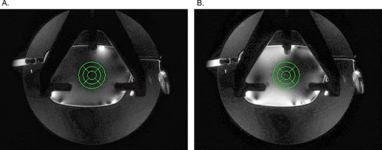 |
Figure 1 Birefringent pattern shown in the lens internal stress image with loose screw (A) and tight screw (B). |
Internal Lens Stress Measurement
In this study, a newly designed digital colmascope (Moptim, Shenzhen, China) was used to measure the internal stress of the mounted spectacle lenses. The colmascope optical system is composed of a LED backlight board and two circular polarizers. Image analysis software was loaded into the computer system connected to the colmascope. A set of circular polarizers is the most notable component of the colmascope. Unlike the traditional crossed linear polarizer set, the circular polarizer set has better repeatability and stability in evaluating internal lens stress. Briefly, the light emitted from the LED backlight board was filtered by the first circular polarizer. Then the outgoing linearly polarized light go through the myopia lens to be tested and the second circular polarizer. The final linearly polarized light distribution image was analyzed using software to characterize the internal lens stress. The tested lens image was divided into nine zones by three concentric circles and two intersecting lines. The diameters of the three concentric circles were 3, 6, and 9 mm, respectively. The angle between the two intersecting lines was 45°. Under constant illumination, the image light intensity of each pixel was quantized from 0 to 255, with 0 defined as the dimmest and 255 defined as the brightest. If the number of pixels in Zone M is i, the light intensity of pixel I is XMi, and the mean brightness of Zone M is determined using the following formula:
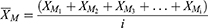
where  is the mean brightness of Zone M. The variance of the light intensity of Zone M is given in the following formula:
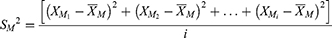
where  is the variance of the light intensity of Zone M. The magnitude of the internal lens stress was characterized according to the mean light intensity of each zone.
The internal lens stress was evaluated after the measurement of the optical center and vertex power of the lenses by an automated focimeter (LM-600P, Nidek, Japan). The alignments of the three points marked on the lenses and the lines on the load table of the digital strain tester were checked before each test. The measurements were repeated at least 3 times. The first two of three measurements were used to assess the repeatability of the internal lens stress measurements.
Retinal Image Quality Measurements
Residual refractive error and retinal image quality were measured using OPD Scan III (Nidek, Inc. Aichi-ken, Japan) with the corrected spectacle in place. The measurement axis of the instrument, the optic center of each spectacle lens, and the patient’s sight line were aligned with the pupil on the real-time image display provided by OPD Scan III. The internal telescopic relay lenses in the OPD Scan III made the wavefront sensor optically conjugate to the spectacle plane. The MSE of each lens was calculated by adding half the cylinder power to the sphere. The cylinder axis was computed using the established standard notation.6 Power vectors are represented by the following equations:7

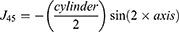
where J0 and J45 are computed at axis 0 and 45.
The parameters of retinal image quality, including on-axis higher-order wavefront aberrations (HOA), total modulation transfer function (MTF), and point spread function, were evaluated for a 4.0-mm pupil in this study. The HOAs were computed by expanding the set of orthogonal Zernike polynomials. The root mean square (RMS) was used to present the magnitudes of the Zernike coefficients. All measurements were performed with natural pupils. Room lights were dimmed to maintain large pupil diameters. All examinations were performed by the same trained operator. The measurements were repeated at least 3 times in each eye, and the best-focused properly aligned image was selected. As the bilateral eyes were not compared, the measurements from both eyes of each volunteer were used for the statistical analysis.
Statistical Analysis
As determined by the Shapiro–Wilk test, all data were non-normally distributed, except the data of the two successive measurements of the internal lens stress from 21 loose-mounted left lenses. Thus, in addition to the mean, the median was also used for statistical description. The paired Student t test was used to assess the difference between the two successive measurements of 21 loose-mounted right lenses. The intraclass correlation coefficient was used to assess data repeatability. The Bland-Altman method was used to calculate the 95% limits of agreement (LoA).
The paired-samples Wilcoxon signed-rank test was used to assess differences in internal lens stress, residual refractive error, and retinal image quality parameters of the corrected eyes between loose and tight mounting. Given the internal lens stress in the different zones, a related-samples Friedman two-way analysis was used to determine whether the differences between the medians of the internal lens stress of the nine zones were statistically significant. Bonferroni correction was used for post hoc analysis if the result of the overall comparison was significant. A calculated two-tailed P value of <0.05 was considered statistically significant. All data were analyzed using the SPSS software (version 20; SPSS, Inc., Chicago, IL).
Results
Sixty volunteers with a mean age of 26 ± 4.24 years (range, 22–37 years) were recruited, of whom 40 were female. The MSE values of the right and left eyes were −4.32 ± 1.98 D (range, −8.75 to 0.00 D) and −4.45 ± 2.04 D (range, −10.63 to −1.00 D), respectively. Agreement of the first two successive measurements of the 21 loose-mounted right lenses was good for the digital strain viewer readings in the nine lens zones, with intraclass correlation coefficients > 0.984. The comparison of the means of the two successive acquisitions in all lens zones is shown in Table 1. No significant difference was found between the first two acquisitions. Bland-Altman plots of the two successive measurements in the nine zones are shown in Figure 2.
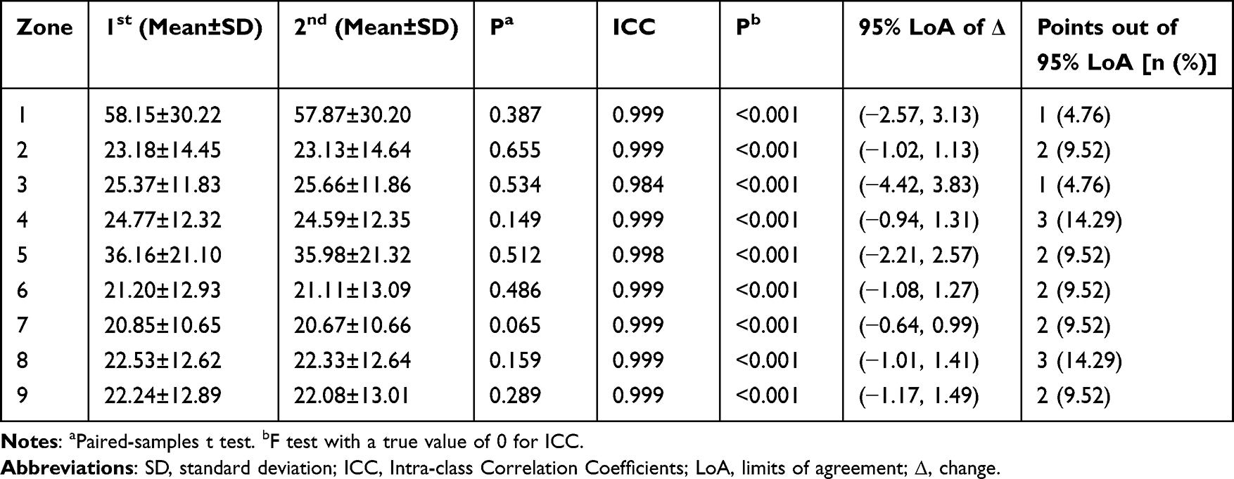 |
Table 1 Comparison and Agreement of Two Successive Measurements Obtained with the Digital Strain Viewer (N = 21) |
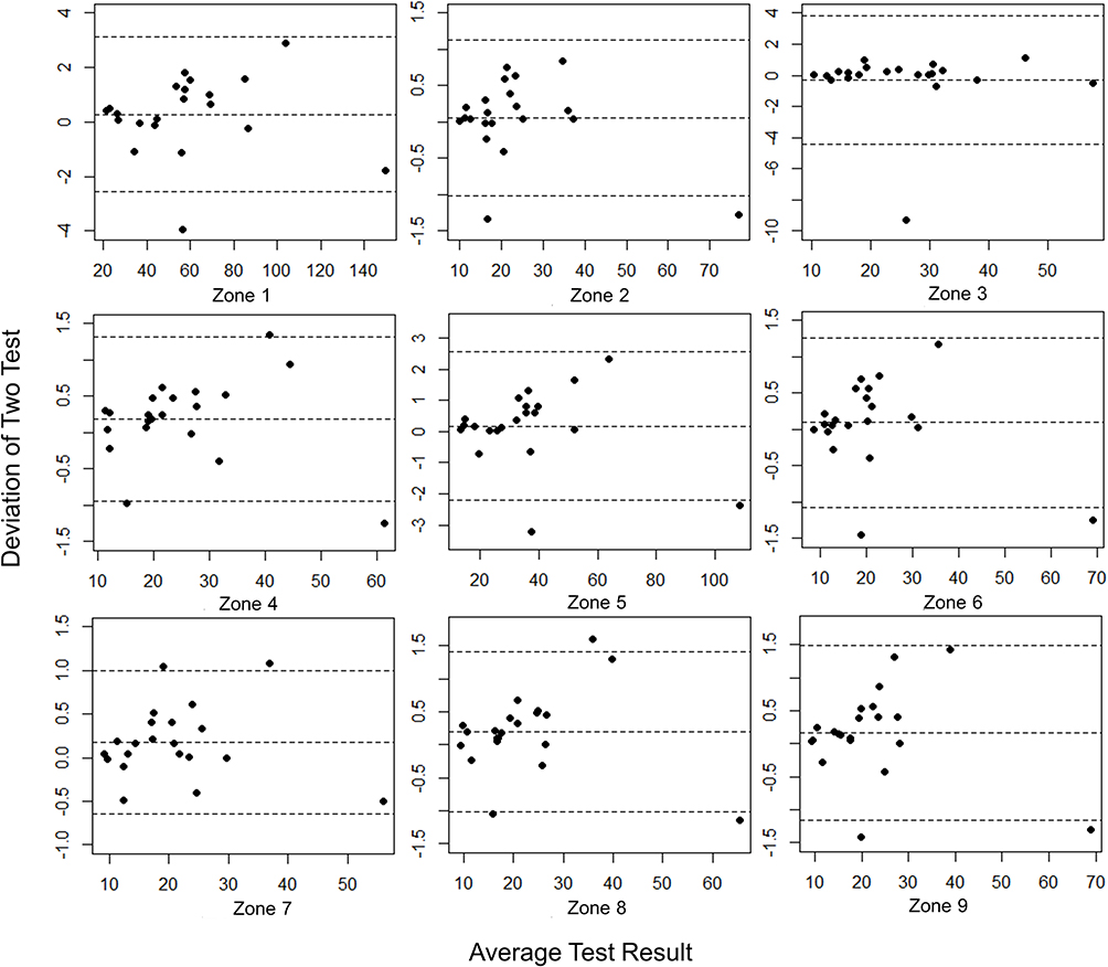 |
Figure 2 Bland-Altman plots of two successive measurements obtained with the digital strain viewer in nine zones. |
The internal lens stress was measured in the nine zones of the tight- and loose-mounted spectacle lenses, and the measurements with their median values are shown in Figure 3 and Table 2. The internal lens stress of the tight-mounted spectacles was significantly elevated compared with that of loose-mounted spectacles in all nine zones (P < 0.001), as shown in Figure 4 and Table 2. The internal lens stress in the same zone was further compared between the right and left lenses with different mounting tightness. As shown in Table 2, the internal lens stress of the left lenses increased significantly compared with that in the right lenses in the same zone (P < 0.05), except in Zone 1 with tight mounting, where the internal lens stress of the left lenses was slightly higher than that in the right lenses but not statistically significantly (t = 0.029, P = 0.977).
 |
Table 2 Description and Comparison of the Internal Stress Differences of Myopia Spectacle Lenses (N = 60) |
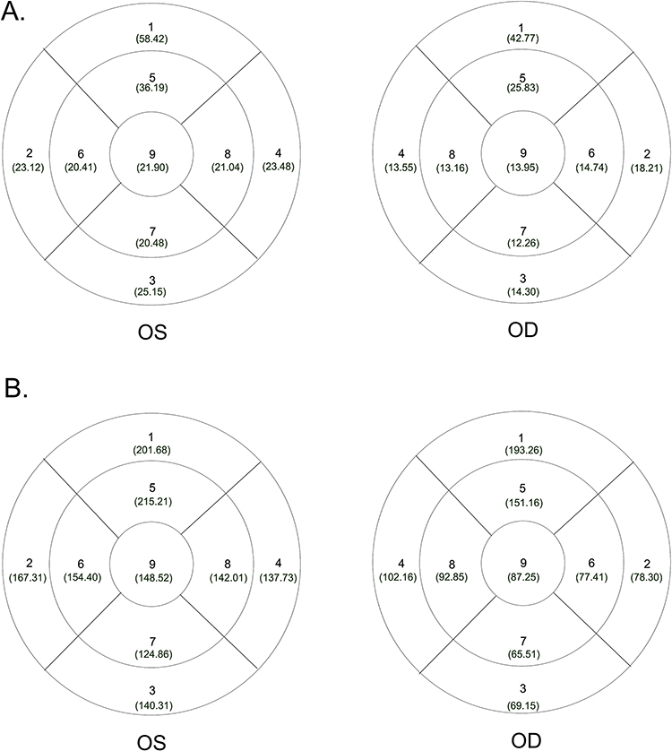 |
Figure 3 Lens zone numbering method of the mounted spectacle from the digital strain viewer image in a different mounting state (interior view). The tested lens was divided into nine zones by three concentric circles and two intersecting lines. The diameters of the concentric circles are 3, 6, and 9 mm. The angle between the two lines is 90°. The medians of the internal lens stress in the different zones are placed inside the brackets below the zone number. (A) Loose mounting. (B) Tight mounting. |
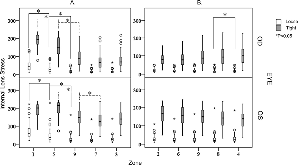 |
Figure 4 Box plots of the internal lens stress distribution in the different zones. Statistically significant differences between the different zones after the post hoc tests are marked with lines and asterisks. (A) Vertically arranged zones. (B) Horizontally arranged zones. * P<0.05. |
A significant difference in median internal lens stress was observed among the nine zones of the right lenses, both in the loose-mounted spectacles (Z = 311.449, P < 0.001) and tight-mounted spectacles (Z = 339.067, P < 0.001). Similar results were found in the nine zones of the left lenses in the loose-mounted spectacles (Z = 286.320, P < 0.001) and tight-mounted spectacles (Z = 239.764, P < 0.001). The Bonferroni correction used as a post hoc test revealed the difference between the horizontally and vertically arranged zones, and the statistically significant differences are shown in Figure 4. The differences were mainly derived from the comparisons of the five vertically arranged zones (P < 0.05).
Unexpectedly, no significant difference in the central residual refractive error of the corrected eyes was found between loose- and tight-mounted spectacles. Similarly, no significant differences in the retinal image quality parameters of the corrected eyes, including HOA, MTF, and Strehl ratio, were observed between the loose- and tight-mounted spectacles, as shown in Table 3.
 |
Table 3 Comparisons of the Central Residual Refractive Errors and Visual Image Quality Parameters of the Corrected Eyes Between Loose- and Tight-Mounted Spectacles (N = 60) |
Discussion
Colmascope or polariscope is an instrument with a light source and two crossed polarizing filters designed for determining the stress pattern of lenses. Currently, the linear polarization technique is mainly applied in strain viewers. However, instruments using this technique could only provide qualitative data because of the characteristics of linearly polarized light. In addition, digital technology speeds up the image acquisition and data processing of polarizers, which make the quality control of materials easier for quantitative analysis, such as in the manufacturing of glasses and plastics.8,9 The newly designed digital strain viewer with the circular polarization technique was used to improve the repeatability of the instrument in the present study. In this study, the digital strain viewer provided reproducible results between the measurements, with intraclass correlation coefficients ranging from 0.985 to 0.999. Therefore, the digital strain viewer is reliable, and a single measurement appears to be sufficient.
Normally, the eyewire screw is tightened once the lens is seated. Forcibly tightened eyewire screws exert excessive edge strain on the lens. In our study, the internal lens stress in all nine zones, measured using a colmascope, increased significantly with tight mounting compared with loose mounting. However, the increase in internal lens stress was not distributed evenly and symmetrically. Generally, the internal lens stress in the five zones on the vertical axis decreased gradually from superior zone (Zone 1) to the inferior zone (Zone 7) and then increased slightly in the inferior peripheral zone, which was near the rim of the lens (Zone 3). This trend was more obvious in the tight-mounted lenses. In the horizontally arranged zones, the difference in internal lens stress was mainly derived from the comparison between the symmetrical peripheral zones (zones 2 and 4) and the pericentral zones (zones 6 and 8). The temple peripheral zones showed greater internal lens stress than the nasal peripheral zones with tight mounting. In a previous study, Peral et al measured the effect of the tangential force on a set of CR-39 spherical lenses exerted by the circular metal rim by using the moiré technique.2,3 The researchers found strong aspherization at the outer regions of the lens surfaces, whereas the on-axis astigmatism was small. In agreement with their study, our results also show that the internal lens stress was uniform across the different lens regions. Nevertheless, we observed that the internal lens stress distribution was not centrosymmetric, with significant variation on the vertical axis. This may be due to the fact that instead of circular frames, rectangle frames were used in the present study, resulting in a more asymmetrical compression of the lens regions. Various factors can further influence lens stress pattern, including the shape of the transition between adjacent lens sides, the design of the lens edge, and the location of the rim screw of the quadrilateral lenses. First, lens stress may be distributed more evenly in lenses with a smooth and gradual transition than in those with an abrupt transition. Second, the stress distribution is also affected by the shape and thickness of the edge. Finally, the impact of the rim screw location should not be neglected. The stress may be concentrated around the screw corner. Therefore, when evaluating a mounted eyewire, it is important to consider that lens stress patterns can be affected by comprehensive factors.
We compared the internal lens stress of the same zone between the right and left lenses, both with different levels of mounting stress; the internal lens stress of the left lenses was significantly elevated compared with that of the right lenses. This may be related to the lens mounting sequence of the spectacles. In our study, right lenses were mounted before left lenses, as in actual practice. As a result, the second lens was usually unconsciously mounted more tightly than the first lens. In spite the significantly elevated internal lens stress in the two superior periphery zones (zones 1 and 5), the effect superimposed on the central residual refractive error was very small. Smith et al reported that the contribution of lens warpage to vertex power and effective power errors was relatively small for the negative prescriptions, whereas the variation of image distortion increases extremely rapidly with a given prescription for an increased eye spectacle size.5 Consistent with the previous study, the effect of internal lens stress variation was limited in the central of the minus lens in terms of the retinal image quality parameters evaluated in our study. Although the internal stress in the superior periphery lens zones changed drastically, it was not large enough to distort the central retinal image.
Therefore, two points should be emphasized when assembling spectacles. First, the frame should be fitted properly. It is not clinically rare that a wearer does not likely tolerate spectacles with poorly fit frames, even if the prescription is correct.10 For conventional eyewear, the frame height is based on the combination of the eye, eyebrow, and orbit positions. Normally, the optical center does not remain in the middle of the lens once it has been edged. However, in any case, the frame should be fitted at a height that conforms to standards to make sure that each lens of a corrective eyewear is positioned with its optical center in front of the eye. If the optic axis of the lens passes through the center of the pupil, the lens is centered in front of the eye. The optic center should be in line with the pupil center, whereas the lens optic center should be located within 2 mm vertically around the geometric center. This prevents the wearer from looking through the upper area with high internal stress, which may cause a bad visual image that may result in discomfort with the vision experience. Second, forcibly tightening the screw should be avoided when assembling spectacles, as this may place excessive stress on the lens. In an eyewear with an overly tightened screw, the lens may chip along the edge if struck if made of glass or may warp if made of plastic. Excessive edge strain should be checked using a colmascope.11 Lens warping from eyewire pressure may cause lens damage, especially from its long-term effect. Therefore, excessive compression should be avoided in the mounting process of CR-39 lenses in actual practice to ensure the safety of the spectacles when worn.
Conclusion
In conclusion, the internal lens stress measurements provided by this newly designed digital colmascope have good repeatability. The applied forces generated by the rim screw changed the peripheral optical performance of the mounted myopia lenses but exerted a negligible impact on the central residual refractive error and visual image quality. Although these effects were negligible, the proper fitting of the spectacles should be emphasized in consideration of wearing comfort. Tight mounting should be avoided, as excessive compression on the lenses may cause lens damage over time.
Acknowledgments
We thank Prof. Renyuan Chu and Moptim Company, the producer of the digital strain viewer, for providing the colmascope used in this study.
Funding
This study is funded by the 2017 annual scientific research project of the Hunan Provincial Health and Family Planning Commission (B2017039).
Disclosure
The authors declare no conflicts of interest related to this article.
References
1. Holden BA, Fricke TR, Wilson DA, et al. Global prevalence of myopia and high myopia and temporal trends from 2000 through 2050. Ophthalmology. 2016;123(5):1036–1042. doi:10.1016/j.ophtha.2016.01.006
2. Alonso J, Peral A, Sanz JC, et al. Measurement of mechanical warpage in CR-39 lenses. Ophthalmic Physiol Opt. 1997;17(1):81–87. doi:10.1111/j.1475-1313.1997.tb00528.x
3. Peral A, Alonso J, Sanz JC, et al. Deflectometric measurement of mechanical spectacle lens deformation. Ophthalmic Physiol Opt. 2000;20(6):473–479. doi:10.1111/j.1475-1313.2000.tb01125.x
4. Dowaliby M, Nichols E, Bailey ME. Comparative study involving bitoric effect of hard resin lenses mounted in optyl frames, zylonite frames, and metal frames. Am J Optom Physiol Opt. 1980;57(2):109–112. doi:10.1097/00006324-198002000-00006
5. Smith FD, Wientzen RV. Prediction of visual effects from the warpage of spectacle lenses. Am J Optom Arch Am Acad Optom. 1973;50(8):616–631. doi:10.1097/00006324-197308000-00002
6. Bullimore MA, Fusaro RE, Adams CW. The repeatability of automated and clinician refraction. Optom Vis Sci. 1998;75(8):617–622. doi:10.1097/00006324-199808000-00028
7. Thibos LN, Wheeler W, Horner D. Power vectors: an application of Fourier analysis to the description and statistical analysis of refractive error. Optom Vis Sci. 1997;74(6):367–375. doi:10.1097/00006324-199706000-00019
8. Ajovalasit A, Petrucci G, Scafidi M. RGB photoelasticity applied to the analysis of membrane residual stress in glass. Meas Sci Technol. 2012;23(2):025601. doi:10.1088/0957-0233/23/2/025601
9. Kramer S, Beiermann B, Davis D, et al. Characterization of mechanochemically active polymers using combined photoelasticity and fluorescence measurements. In: Proulx T, editor. Application of Imaging Techniques to Mechanics of Materials and Structures. Vol.4. New York: Springer New York; 2013:167-178
10. Kintner EA. The Relative Role of Physical Feature of Spectacles as Factors in Wearing Comfort. Master’s Thesis, Bloomington, IN: Indiana University; 1970.
11. Brooks CW, Borish IM. Lens curvature and thickness. In: Brooks CW, Borish IM, editors. System for Ophthalmic Dispensing.
 © 2023 The Author(s). This work is published and licensed by Dove Medical Press Limited. The full terms of this license are available at https://www.dovepress.com/terms.php and incorporate the Creative Commons Attribution - Non Commercial (unported, v3.0) License.
By accessing the work you hereby accept the Terms. Non-commercial uses of the work are permitted without any further permission from Dove Medical Press Limited, provided the work is properly attributed. For permission for commercial use of this work, please see paragraphs 4.2 and 5 of our Terms.
© 2023 The Author(s). This work is published and licensed by Dove Medical Press Limited. The full terms of this license are available at https://www.dovepress.com/terms.php and incorporate the Creative Commons Attribution - Non Commercial (unported, v3.0) License.
By accessing the work you hereby accept the Terms. Non-commercial uses of the work are permitted without any further permission from Dove Medical Press Limited, provided the work is properly attributed. For permission for commercial use of this work, please see paragraphs 4.2 and 5 of our Terms.