")
Back to Journals » Cancer Management and Research » Volume 13
Verification of Guiding Needle Placement by Registered Ultrasound Image During Combined Intracavitary/Interstitial Gynecologic Brachytherapy
Authors Zeng J, Liu Z, Jiang S, Pang Q, Wang P
Received 27 November 2020
Accepted for publication 14 January 2021
Published 24 February 2021 Volume 2021:13 Pages 1917—1928
DOI https://doi.org/10.2147/CMAR.S294498
Checked for plagiarism Yes
Review by Single anonymous peer review
Peer reviewer comments 2
Editor who approved publication: Professor Seema Singh
Jing Zeng,1,2 Ziqi Liu,3 Shan Jiang,3 Qingsong Pang,1 Ping Wang1
1Tianjin Medical University Cancer Institute and Hospital, National Clinical Research Center for Cancer, Key Laboratory of Cancer Prevention and Therapy, Tianjin, Tianjin’s Clinical Research Center for Cancer, Tianjin, People’s Republic of China; 2Department of Gynecologic Oncology, Tianjin Central Hospital of Gynecology and Obstetrics, Affiliated Hospital of Nankai University, Tianjin, People’s Republic of China; 3School of Mechanical Engineering, Tianjin University, Tianjin, People’s Republic of China
Correspondence: Ping Wang
Tianjin Medical University Cancer Institute and Hospital, National Clinical Research Center for Cancer, Key Laboratory of Cancer Prevention and Therapy, Tianjin, Tianjin’s Clinical Research Center for Cancer, Tianjin, 300060, People’s Republic of China
Email [email protected]
Purpose: Our previous research demonstrated that under ideal conditions, rigid registration between MRI images and US images had high accuracy for real-time image guidance. The work presented in this paper focused on the application of the previously established procedures to a new context, including preoperative CT images.
Materials and Methods: We used a template to calibrate the US probe and completed the registration between preoperative CT images and US images. Marker experiments on the accuracy of real-time needle trajectories in CT images were performed using micro electromagnetic sensors. Pelvic phantom experiments were carried out to test the registration accuracy between CT and US images, in addition to registration accuracy between US images and real-time needle trajectories (real-time space model).
Results: The US probe calibration error in CT images was 0.879 ± 0.149 mm. The difference of registration between US images and CT images was 0.935 ± 0.166 mm in the axial plane (n = 30) and 0.916 ± 0.143 mm in the sagittal plane (n =12). The difference of registration between US images and the needle’s real-time trajectories was 0.951 ± 0.202 mm.
Conclusion: Under ideal conditions, rigid registration between CT images and US images had high accuracy for real-time image guidance.
Keywords: registered ultrasound image, gynecologic brachytherapy, rigid registration, image-guidance
Introduction
Brachytherapy has been widely used in radiation therapy for cancer, and its efficacy in cervical cancer treatment has been well described. Three-dimensional (3D) imaging modalities, including computed tomography (CT) and magnetic resonance imaging (MRI), have been used in brachytherapy treatment.1,2 Further evidence has been provided that 3D image-guided brachytherapy (3D-IGBT) can improve the prognosis3,4 and reduce the incidence of adverse events.5–7 However, cervical cancer incidence is high in low- and middle-income countries globally.8 The huge patient burden associated with cervical cancer and the relatively high economic cost of introducing CT and/or MRI pose challenges to implementing 3D-IGBT.9 Ultrasound (US) is a relatively extensive and economical method to obtain a sectional image, widely used in diagnosing abdominal and gynecological diseases. The application of transabdominal US10,11 in the brachytherapy of cervical cancer has also been reported. St-Amant et al12 used three-dimensional (3D) transabdominal US images with CT localization images to accurately outline the therapeutic target area and surrounding organs at risk (OARs) and calculated the dose using CT parameters. It showed that the dose distribution of a 3D transabdominal US combined with CT was similar to that of brachytherapy planning guided by MRI images. This not only reduced the overestimation of therapeutic target volume caused by CT’s indistinguishability of soft tissue but also improved the dose coverage of the therapeutic target. The US’s image-guidance technique, combined with CT, helps lighten cervical cancer patients’ burden in low-and middle-income countries.
Medical image registration mainly includes rigid registration and deformable registration. As existing deformable registration algorithms are time-consuming and are not suitable for real-time applications, US image registration usually uses rigid registration.13 The “rigidity” hypothesis simplifies the complexity of registration and has the critical advantage of real-time. It is assumed that the target’s anatomical structures do not deform or distort during the process of image acquisition. Registration between preoperative CT/MRI images and intraoperative US images is the key to guarantee the precise needle placement because the real-time patient anatomy information, preoperative images, and needle’s real-time position relative to the target and surrounding anatomy will display together in one coordinate system. Clinicians do not need to mentally collate the 2D US image planes to the patient’s 3D anatomy. Preoperative images are displayed together with real-time US images to provide the medical team with the latest anatomical information and realize image guidance. Based on the optical sensor or electromagnetic sensor fixed to the US probe, the US images and preoperative images will be unified into one coordinate system by a series of space transforms. Wang et al proposed a 2D US probe calibration method. By detecting and analyzing the US artifacts’ temporal signal when sweeping the US probe over the phantom, the probe’s imaging plane and the image features can be reliably identified. Then the features are fed to a nonlinear optimizer to estimate the calibration parameters.14 Toews et al calibrated and assessed an externally tracked 2D US probe’s calibration quality by scanning arbitrary, natural tissues.15
Our previous research suggested that rigid registration between MRI images and US images had high accuracy for real-time image guidance under ideal conditions. Registered US images performed an accurate combination of effective visualization and image guidance during visual needle insertion in gynecologic brachytherapy.16 To gain further insight into the involvement of preoperative images, the work presented in this paper focused on applying the previously established procedures to a new context, including preoperative CT images.
Materials and Methods
US Probe Calibration
We used a template to calibrate the 2D US probe (DP-50, Mindray, China). The pixel size of 2D US images was 0.169 × 0.169 mm2. The calibration template consisted of three acrylic plates that were attached with regularly arranged spherical markers 6 mm in diameter. Two parallel cotton threads existed in the calibration template. The plane constructed by the threads was perpendicular to the upper plate and passed through the maximum cross-sections of a column of markers.
During the calibration process, the electromagnetic transmitter (mid-range transmitter, Ascension Technology Corporation, USA) coordinate system was the 3D world coordinate system W. Three coordinate systems existed in 3D world coordinate system W: the US image coordinate system I, the electromagnetic sensor (Model 800 sensor, Ascension Technology Corporation, USA) coordinate system R, which was fixed to the US probe, and the calibration template coordinate system P. US probe calibration was used to estimate the similarity transformation RTI, which mapped 2D US image coordinates to 3D electromagnetic sensor coordinates and required the calibration template to act as an intermediary. We supposed that a point existed in the system I as well as system R. The following equation could be obtained:
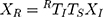
where XR=(x,y,z,1)T was the homogeneous coordinates of the point in system R; XI = (u,v,0,1)T was the homogeneous pixel coordinates of the point in the system I; TS was a 4 4 diagonal scaling matrix converting US spatial units (pixels) to world distance units (mm), which had the following form:
where Su and Sv were scaling parameters along the x and y directions of the US image which would be provided by the US system. RTI was a 4 4 homogenous transform matrix which had the following form:
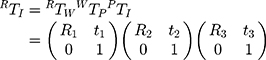
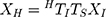
where RTW, WTP, and PTI were 4 4 homogenous transform matrices; R1, R2, and R3 were rotation matrices; t1, t2, and t3 were translation vectors. RTW was a 3D rigid transform mapping 3D world coordinates to 3D electromagnetic sensor coordinates, which were provided by the current output data (x, y, z, a, e, r) from the electromagnetic tracker, where x, y, and z were 3D world coordinates of the electromagnetic sensor’s origin, a, e, and r were heading, tilt and roll of the sensor. Figure 1 illustrates the space coordinate transformation relationships in US probe calibration. WTP was a 3D rigid transform mapping 3D calibration template coordinates to 3D world coordinates which could be solved by the algorithm based on singular value decomposition (SVD). PTI was a 3D similarity transform mapping 2D US image coordinates to the 3D calibration template coordinates, which could also be solved by the algorithm based on SVD.
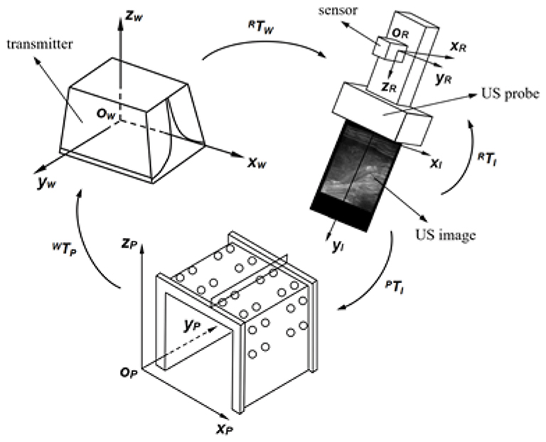 |
Figure 1 Space coordinates transformation relationships in US probe calibration. |
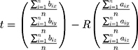
The 3D transform matrix solution was to explore the optimal rotation matrix R and the optimal translation vector t to minimize the distance between homologous points in two different coordinate systems. For WTP:
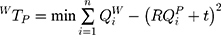
where QiP=(x, y, z)T was the calibration template coordinates of a point which could be obtained by the location of it; QiW=(x, y, z)T was the 3D world coordinates of the point which could be obtained by using the tip of a needle probe fixed by an electromagnetic sensor to touch it. The tip’s 3D world coordinates could be identified by its position concerning the electromagnetic sensor coordinate system and transform matrix WTR.
We used the upper vertexes of the markers from the calibration template as selected points. It was supposed that two sets of points chosen from system P and system W were A= {a1, a2, …, an} and B={b1, b2, …, bn}. We decentralized set A and set B, and presented them in matrix X and matrix Y, which produced:
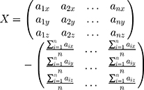
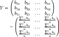
The SVD was used to decompose matrix XYT. The rotation matrix R and translation vector t of WTP could be obtained. The following formulas showed the procedure:


We filled a container with water and leant the calibration template against the wall, and fixed an electromagnetic sensor to a linear array ultrasonic probe. Figure 2A shows a 3D printed slider. The slider made the US probe direction consistent when sweeping the template, as shown in Figure 2B. The US image depth was set as 10 cm. We moved the US probe by the slider until the US image gave the maximum visibility of both two cotton threads, which meant the current slice passed through the column of markers’ maximum cross-sections under the cotton threads. We captured this image and got the current transform matrix RTW provided by the electromagnetic tracker. The image was scaled along x and y directions with Su and Sv to convert US spatial units (pixels) to world distance units (mm). A group of contour points of maximum cross-sections of markers under threads was chosen as reference points to do the registration. Since the slider could locate the US probe and made the US image horizontal, the maximum cross-sections had definite locations in the US image, and the 2D US image coordinates of each point could be obtained automatically. The coordinate in z-direction was identified as 0. We set the top center of the US image as the coordinate origin to ensure the PTI was unchanged no matter the scan width or depth changed. We used the algorithm based on SVD to solve PTI. From the principle of ordered multiplication of RTW, WTP and PTI, the transform matrix RTI would be solved.
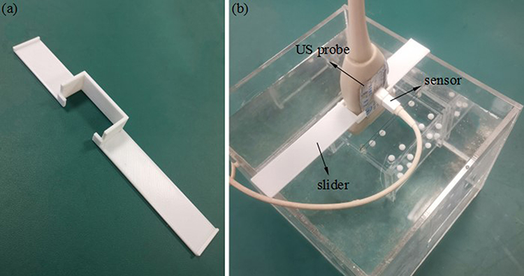 |
Figure 2 (A) 3D printed slider. (B) The slider controlled the direction of the US probe. |
Registration Between US Images and Preoperative Images
The registration between US images and preoperative images provided the basis for the cooperation between updated anatomy information and preoperative planning during the operation. Preoperative images coordinate system H existed in the treatment planning system (TPS). Our research team developed the TPS we used for cervical cancer brachytherapy. This registration was to estimate the similarity transformation HTI which mapped 2D US image coordinates to 3D preoperative image coordinates. We supposed that a point existed in the system I as well as system H, we could obtain the following equation:
Where XH = (x, y, z, 1)T was the homogeneous coordinates of the point in system H; XI = (u, v, 0, 1)T was the homogeneous pixel coordinates of the point in the system I; TS was the 4 4 diagonal scaling matrix converting US spatial units (pixels) to world distance units (mm). HTI had the following form:
where HTW, WTR and RTI were 4 4 homogenous transform matrices; R1, R2, and R3 were rotation matrices; t1, t2, and t3 were translation vectors. HTW was a 3D rigid transform mapping 3D world coordinates to 3D preoperative image coordinates. Using the tip of the needle probe to touchpoints in 3D world coordinate system W, and picking up the corresponding points in preoperative images, HTW could be solved by the algorithm based on SVD. WTR was the inverse matrix of RTW which was provided by the electromagnetic tracker. RTI had been solved by US probe calibration. From the principle of ordered multiplication of HTW, WTR and RTI, the transform matrix HTI would be solved.
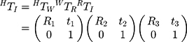
Interstitial Brachytherapy Applicator and Real-Time Space Model
The brachytherapy applicator included an intrauterine catheter and needed interstitial needles, which were located and supported by a vaginal template. We fixed an electromagnetic sensor at the terminal to track the intrauterine catheter’s position and threaded a micro electromagnetic sensor along the tube wall into the tip. The intrauterine catheter and interstitial needle were made by PEEK, which was standardly available and had been used in electromagnetism applications.14 The needle tip was made by 3D printing using Vero-clear to insert the needle smoothly. To track the needle’s position, we threaded a micro electromagnetic sensor along the needle wall into the end of the needle shaft, as shown in Figure 3A, and fixed an electromagnetic sensor at the terminal, as shown in Figure 3B. Since the needle’s inner diameter was 1.5 mm, we also set a small ring at the micro sensor’s tip to make it locate at the end of the needle shaft, as shown in Figure 3C. The needle tip’s 3D world coordinates could be identified by its position concerning the microsensor coordinate system and the transform matrix WTR. In this way, the intrauterine catheter’s and interstitial needle’s real-time space model could be drawn in TPS by the transform matrix HTW.
 |
Figure 3 (A) The micro electromagnetic sensor was fixed to the needle. (B) The electromagnetic sensor was fixed to the needle. (C) The microsensor was located at the end of the needle shaft. |
Marker Experiment
The marker experiment was designed to test the needle’s real-time space model’s position accuracy in the 3D preoperative image coordinate system and the accuracy of registration between US images and preoperative images.
The accuracy of the transform matrix HTW determined the needle’s real-time space model’s position accuracy in the 3D preoperative image coordinate system, especially the needle tip’s real-time position accuracy. The calibration template was given a CT (Philips, Brilliance BigBore) (slice thickness, 1 mm; scanning matrix, 512 × 512; pixel size, 0.752×0.752 mm2) scan. We chose the highest spherical points of some markers on lateral acrylic plates as selected points. The transform matrix HTW was solved using the needle probe’s tip to touch them and pick up the CT images’ corresponding points. We put the calibration template at five different positions in system W to change the transform matrix HTW. After solving HTW at each position, we used the tip of the needle probe to touch the upper vertexes of 6 markers randomly selected on the calibration template’s upper plate successively to get their 3D world homogeneous coordinates. Then we pre-multiplied the homogeneous coordinates by the solved HTW to get their transformed homogeneous coordinates. Accordingly, the points’ 3D CT image coordinates were obtained by being picked up in CT images. By calculating the distance between transformed coordinates and 3D CT image coordinates for each point, we got 30 differences in total.
The accuracy of the transform matrix HTI determined the accuracy of registration between US images and preoperative images. We did US probe calibration and completed the registration between US images and calibration template’s CT images five times. After finishing the registration, we moved the US probe to scan six markers on the calibration template’s upper plate successively. When the US image slice passed through a selected marker’s sphere center, we obtained the sphere center’s coordinates in this registered US image. The software calculated the circle’s diameter by picking up three non-collinear points on the outline of a random cross-section in a registered US image. If the diameter was in the range of 6 0.2 mm, we could regard it as the maximum cross-section, and the sphere center’s coordinates in a registered US image could be calculated. Accordingly, the sphere center’s 3D CT image coordinates could be obtained easily. By calculating the distance between the sphere center’s coordinates in registered US images and CT images for each marker, we got 30 differences in total.
Phantom Experiment
We used phantom to simulate real surgery, as shown in Figure 4. A typical uterus was segmented from a patient image and formed from agar mixture to provide an additional landmark in the US image (40 g agar powder and 6 g cellulose powder per 1 L distilled water) mold created. Granulated sugar was also added into the uterus appropriately to avoid water seepage. The phantom background was an agar mixture containing 20 g agar powder, 60 mL glycerol, and 10 g cellulose powder per 1 L distilled water to mimic soft-tissue scatter in US images. An agar lump had the same composition as the uterus phantom to support it.16,17 The whole phantom was kept in a container with plastic particles marked on the container’s inner wall.
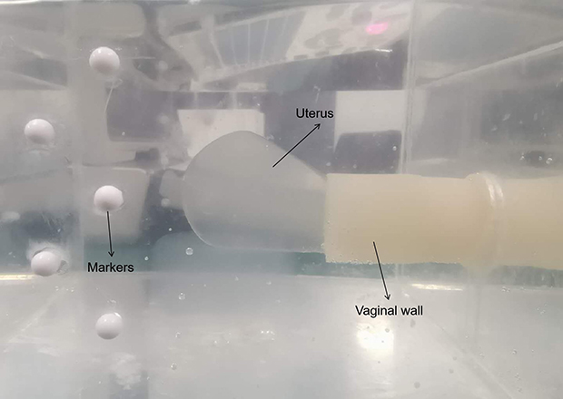 |
Figure 4 The phantom. |
The phantom experiment was designed to test the accuracy of registration between US and CT images and the needle’s real-time space model in the US image. Figure 5 shows the workflow of the phantom experiment.
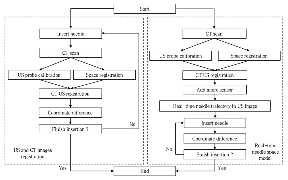 |
Figure 5 The workflow of the phantom experiment. |
We first confirmed the registration accuracy between US images and CT images. We used the axial ultrasonic image positioning needle and used the sagittal ultrasonic image to evaluate the needle depth. The registration accuracy between the CT image and US image was verified on these two planes. The phantom was placed in CT scans with 1-mm slice thickness. After the ultrasonic probe calibration, the CT image was registered with the US image according to the markers’ outline in the CT image. In axial CT images, the needle bar cross-sectional centers of 4 layers with a distance of 5 mm were extracted, and the coordinates were obtained. After that, the phantom was scanned with an ultrasonic probe and adjusted so that the registered ultrasonic image corresponds to four axial CT slices in turn. The center of the cross-section of the needle axis in the registered ultrasonic image was selected to calculate the corresponding point coordinates’ distance in the two modes. In sagittal CT images, slices with needles were searched to detect the endpoint of the needle axis’s longitudinal section. Similarly, we scanned the model with an ultrasonic probe and adjusted it so that the registered US images coincided with these slices continuously. The endpoint of the longitudinal section of the needle shaft was detected in the registered ultrasonic image. The distance between the corresponding point coordinates in the two modes was calculated. We inserted three needles through different peripheral channels. And then, we scanned the phantom five times with a sagittal CT. Finally, we obtained 30 differences in the axial plane and 12 differences in the sagittal plane.
We second tested the accuracy of registration between US images and the needle’s real-time space model. A new phantom was created, which was the same as the previous model. CT scanned the phantom with a 1-mm slice thickness without needle insertion. We did the segmentation and reconstruction of the uterus and vagina in TPS based on the phantom’s obtained preoperative CT images. According to the markers fixed to the phantom’s container, the transform matrix HTW could be solved to realize the registration between the 3D world coordinate system and 3D CT image coordinate system. The intrauterine catheter was fixed with electromagnetic sensors. By tracking the intrauterine catheter’s current position and making the real-time space model in TPS pass through the reconstructed cervix and locate in the reconstructed uterine cavity, the intrauterine catheter was inserted into the phantom. Then we placed the template in the vagina through an intrauterine catheter by the central channel to support it. Six different interstitial needle insertion paths were designed in TPS to test the registration accuracy. After finishing the registration between US images and CT images, we fixed the electromagnetic sensors to an interstitial needle. We inserted the needle along one insertion path by tracking the needle’s current position and drawing the TPS’s real-time space model. We chose five random positions in the path inside the uterus to make the needle stay successively during the needle insertion. The needle tip was set as the reference point. When the needle stopped, we only retained the reconstructed organs and did a US scan of the phantom until the needle tip could clearly be shown in a registered US image. The registered US image, which had the clearest needle tip, was captured, and the needle tip was picked up to obtain its coordinates in the registered US image, as demonstrated. In the meantime, the needle tip’s transformed 3D CT image coordinates were obtained by the micro sensor’s current output data and transform matrix HTW. By calculating the distance between these two kinds of coordinates, we got the difference, reflecting the accuracy of registration between US images and the needle’s real-time model. After inserting the needle along the whole six paths and calculating the distance at each position, we got 30 differences in total.
Our research used the Kolmogorov–Smirnov test to check the distributions of our data with P>0.05. All experimental protocols were approved by Tianjin Medical University Cancer Institute and Hospital. All methods were carried out in accordance with relevant guidelines and regulations.
The study was conducted in accordance with the Declaration of Helsinki (as revised in 2013). The study was approved by the Human Investigation Committee of Tianjin Central Hospital of Gynecology and Obstetrics, Tianjin, China (No. 2020KY098).
Results
Marker Experiment
The mean difference ± SD between the points’ transformed coordinates and 3D CT image coordinates was 0.272 ± 0.081 mm Kolmogorov–Smirnov (K–S test P= 0.830). The mean difference SD between the marker sphere centers’ coordinates in registered US images and CT images was 0.879 ± 0.149 mm (K–S test P= 0.926), as shown in Figure 6.
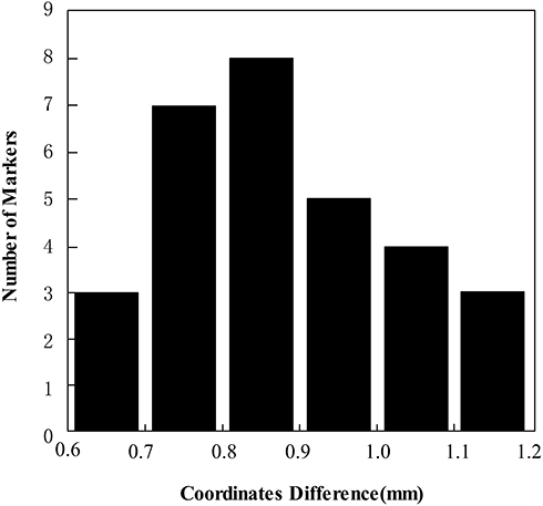 |
Figure 6 Histogram of the marker sphere centers’ coordinate differences between CT images and registered US images for 30 markers. |
Pelvic Phantom Experiment
The mean difference ± SD between the needle tip’s coordinates in registered US images and CT images was 0.935 ± 0.166 mm (K–S test P= 0.996) in the axial plane (n = 30) and 0.916 ± 0.143 mm (K–S test P= 0.958) in the sagittal plane (n =12), as shown in Figure 7. The mean difference ± SD between the registration US images and needle’s real-time space model was 0.951 ± 0.202 mm (K–S test P= 0.974), as shown in Figure 8. Figure 9 shows the registration between US images and interstitial needle’s real-time space model in the insertion paths.
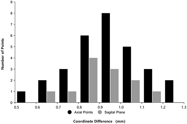 |
Figure 7 Histogram of coordinate differences between US images and registered CT images in the axial plane (black columns) for 30 markers and the sagittal plane (grey columns) for 12 markers. |
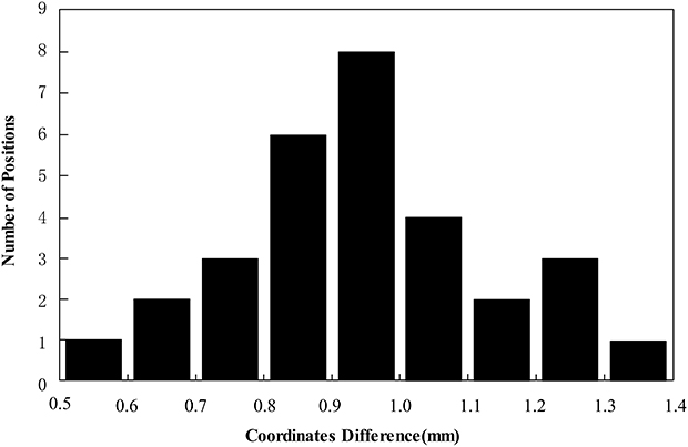 |
Figure 8 Histogram of coordinate differences between the registration US images and needle’s real-time space model for 30 markers. |
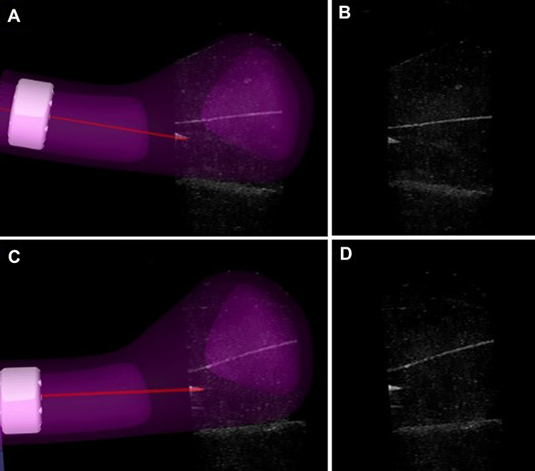 |
Figure 9 The registration between the US image and the needle’s real-time space model in the insertion path. (A, C) Show the registration between US images and interstitial needle’s real-time space model at two of the five positions in two insertion paths. (B, D) Show the US images at two of the five positions in two insertion paths. |
Discussion
Our research group tested the feasibility of guiding needle placement by registered US images in gynecologic interstitial brachytherapy. While the use of preoperative MRI images had been reported16 in our previous study, this experiment demonstrated that under ideal conditions, rigid registration between CT images and US images obtained high accuracy for real-time image guidance.
In the marker experiment, the prime source of the differences between selected points’ transformed coordinates and 3D CT image coordinates was the human factor. The unavoidable deviation occurred when picking up the precise points in CT images and using the needle probe’s tip to touch the precise upper vertexes. Under the presumption that the microsensor located at the needle tip’s center stably without shaking, we could confirm that the needle’s real-time space model had a high position accuracy in the 3D preoperative image coordinate system because the transform matrix HTW was verified to be high-accuracy. The needle tip’s visible real-time position in the phantom’s 3D CT image coordinate system was reliable. The differences between the marker sphere centers’ coordinates in registered US images and CT images had three primary sources. The first source was the deviation that occurs when distinguishing the visibility of two cotton threads during US probe calibration, which mainly depended on the calibration template’s fabrication precision and directly influenced the accuracy of PTI. The second source was the accuracy of HTW which had been verified before. The third source was the deviation that occurs when picking up the three non-collinear points on a cross section’s outline in a registered US image, which mainly depended on the quality of US images and human factors. Because of the coherent imaging process characteristic, US images suffered from a low signal-to-noise ratio that brought unfavorable effects into feature extraction, which created uncertainty in this deviation. Based on the analysis above, the improvements of US image quality and calibration template’s fabrication precision were the keys to improve the accuracy of registration between US images and preoperative images.
The differences between the needle tip’s coordinates in the registered US image and 3D CT image coordinate system had three primary sources. The first and second sources were the accuracies of the transform matrix HTW and transform matrix HTI, respectively, verified in the marker experiment. The third source was the deviation when picking up the needle tip in a registered US image. Similarly, this deviation mainly depended on the quality of US images and the human factor.
In our phantom experiment, the mean difference ± SD between the needle tip’s coordinates in registered US images and CT images was 0.935 ± 0.166 mm in the axial plane (n = 30) and 0.916 ± 0.143 mm in the sagittal plane (n =12). Rodgers et al17 developed a 3D-TRUS system to provide intra-operative needle visualization and localization during interstitial gynecologic brachytherapy. The average 3D Euclidean distance between the corresponding tips of 14 needles was 1.54 ±0.71 mm. Additionally, Wang et al14 reported a similar result. The mean tip error of 1.7 ± 0.5 mm for 15 needles using an active MR tracking system. In our research, the mean tip position difference in the phantom was similar to the pixel size of CT images because these images were captured at a pixel size of 0.752 × 0.752 mm2 (the pixel size of 2D US images was 0.169 × 0.169 mm2) and might be partly attributed to the uncertainty caused by the pixel size of the image.
Navigation is the combined use of tracking and imaging technology to provide an intra-operative visualization of the position of a surgical instrument’s tip relative to the target and surrounding anatomy.18 In interstitial brachytherapy for cervical cancer, needle placement should avoid the OARs, including the bladder and rectum, which is particularly important. Needle tips should extend beyond the target region to ensure dose coverage, potentially impinging on the OARs’ positions.17 The damage of blood vessels during needle insertion can lead to bleeding into the peritoneal cavity or vagina.19 Only tracking the needle’s position and lack of image-guidance during this procedure can cause the above problems.20,21 Consequently, navigation requires more information than just the instrument’s tip. For brachytherapy, shaft information is necessary for dosimetry and the entire needle trajectory.
Most institutions acquire needle’s post-insertion images using CT image-guided. However, due to the needle’s tip’s optimum position cannot be guaranteed during the first insertion, sometimes repeated CT scans will be required to test the adjustment of the needle’s position, whose radiation can damage the patient’s body. Based on the optical sensor or electromagnetic sensor fixed to the needle, the intra-operative location of the needle’s tip can be acquired in real-time with US image-guided, and a CT scan is required only once before the operation. In our CT-based brachytherapy, the mean target registration error (TRE) in the phantom was similar to the MRI-based brachytherapy (0.935 ± 0.166 mm vs. 1.01 ±0.22 mm in the axial plane and 0.916 ± 0.143 mm vs. 1.14 ± 0.20 mm in the sagittal plane). In the MRI-based brachytherapy,16 the mean angle difference ± SD between US images and interstitial needle’s real-time space model was 1.61 ± 0.28 degrees for five needles in the phantom. We will analyze the entire needle trajectory as future work for CT-based brachytherapy.
In brief, the US is the preferred technique to guide interventional treatments due to the good qualities of non-invasion, real-time, cheapness, and convenience. When preoperative images are displayed together with US images, anatomic shifts can easily be visible and measured, thereby providing updated information on the surgical team’s true patient anatomy.18
Finally, several limitations to the present study should be considered for future research. First, our experiments were conducted in modeling pelvic phantom under ideal conditions. The unavoidable mobility of pelvic organs, including the difference between filling the bladder and the intestinal movement, is the inherent limitation for rigid registration between preoperative CT images and US images, producing unreliable image guidance during operation. Even though we used a liquid background in US probe calibration to adjust the speed of sound in human tissues approximately, the US probe should be calibrated through different mediums such as fat, muscle, soft tissues, and bladder filling, which have different speeds of sound in a patient’s procedure. When the transabdominal US passes through the mediums above as the acoustic window before the uterus, US images could be distorted for a real patient. A linear markers model should be fixed in a real patient as features to be identified for US probe calibration. A bionic phantom containing different organs and tissues should be desired. In terms of the different speeds of sound in these media, the gel mixtures of different components can be formed by molds. Second, while the needle tip was made by 3D printing using Vero-clear for inserting the needle smoothly in our study. Some research preferred to use plastic needles with metal obturators to assist insertion smoothly.22 Because the obturator occupied the micro electromagnetic sensor’s position, 3D-printed improved the needle tips with threads at the bottom by 3D-printing technology to assist needle insertion in clinical research. Third, additional studies are needed to construct the needle shaft in preoperative CT image space by threading it along the shaft after needle placement. The organ information reconstructed from intraoperative CT images should also be included in dose planning.
Conclusion
Registered US images performed an accurate combination of effective visualization and image guidance during visual needle insertion in gynecologic brachytherapy. Rigid registration between CT images and US images had high accuracy for real-time image guidance. Our future work will continually go on doing verification based on clinical experiments.
Acknowledgments
We gratefully acknowledge our research team at the Center for Advanced Mechanisms and Robotics, Tianjin University, for their technical assistance. We gratefully acknowledge Tianjin Central Hospital of Gynecology Obstetrics for technical supports. Additional information: correspondence and requests for materials should be addressed to J Z, Z L, S J, Q P, or P W.
Author Contributions
All authors made a significant contribution to the work reported, whether that is in the conception, study design, execution, acquisition of data, analysis and interpretation, or in all these areas; took part in drafting, revising or critically reviewing the article; gave final approval of the version to be published; have agreed on the journal to which the article has been submitted; and agree to be accountable for all aspects of the work.
Funding
This study was supported by the Science and Technology Project of Tianjin (No.18YFZCSY01300), Chinese National Key Research and Development Project (No. 2018YFC1315601), and Health Science and Technology Project of Tianjin (No. ZC20111 and KJ20149).
Disclosure
The authors declare no conflicts of interest for this work.
References
1. Pötter R, Kirisits C, Fidarova EF, et al. Present status and future of high-precision image guided adaptive brachytherapy for cervix carcinoma. Acta Oncol. 2008;47(7):1325–1336. doi:10.1080/02841860802282794
2. Viswanathan AN, Erickson BA. Seeing is saving: the benefit of 3D imaging in gynecologic brachytherapy. Gynecol Oncol. 2015;138(1):207–215. doi:10.1016/j.ygyno.2015.02.025
3. Pötter R, Georg P, Dimopoulos JC, et al. Clinical outcome of protocol based image (MRI) guided adaptive brachytherapy combined with 3D conformal radiotherapy with or without chemotherapy in patients with locally advanced cervical cancer. Radiother Oncol. 2011;100:116–123. doi:10.1016/j.radonc.2011.07.012
4. Simpson DR, Scanderbeg DJ, Carmona R, et al. Clinical outcomes of computed tomography-based volumetric brachytherapy planning for cervical cancer. Int J Radiat Oncol Biol Phys. 2015;93:150–157. doi:10.1016/j.ijrobp.2015.04.043
5. Georg P, Pötter R, Georg D, et al. Dose effect relationship for late side effects of the rectum and urinary bladder in magnetic resonance image-guided adaptive cervix cancer brachytherapy. Int J Radiat Oncol Biol Phys. 2012;82(2):653–657. doi:10.1016/j.ijrobp.2010.12.029
6. Kato S, Tran DN, Ohno T, et al. CT-based 3D dose-volume parameter of the rectum and late rectal complication in patients with cervical cancer treated with high-dose-rate intracavitary brachytherapy. J Radiat Res. 2010;51:215–221. doi:10.1269/jrr.09118
7. Mazeron R, Fokdal LU, Kirchhener K, et al. Dose-volume effect relationships for late rectal morbidity in patients treated with chemoradiation and MRI-guided adaptive brachytherapy for locally advanced cervical cancer: results from the prospective multicenter EMBRACE study. Radiother Oncol. 2016;120:412–419. doi:10.1016/j.radonc.2016.06.006
8. Denny L, Herrero R, Levin C, et al. Cervical cancer. In: Gelband H, Jha P, Sankaranarayanan R, Horton S, editors. Cancer: Disease Control Priorities.
9. Kim H, Rajagopalan MS, Beriwal S, et al. Cost-effectiveness analysis of 3D image-guided brachytherapy compared with 2D brachytherapy in the treatment of locally advanced cervical cancer. Brachytherapy. 2015;14(1):29–36. doi:10.1016/j.brachy.2014.09.002
10. Van Dyk S, Narayan K, Fisher R, et al. Conformal brachytherapy planning for cervical cancer using transabdominal ultrasound. Int J Radiat Oncol Biol Phys. 2009;75(1):64–70. doi:10.1016/j.ijrobp.2008.10.057
11. Narayan K, van Dyk S, Bernshaw D, et al. ultrasound guided conformal brachytherapy of cervix cancer: survival, patterns of failure, and late complications. J Gynecol Oncol. 2014;25(3):206–213. doi:10.3802/jgo.2014.25.3.206
12. St-Amant P, Foster W, Froment MA, Aubin S, Lavallée MC, Beaulieu L. Use of 3D transabdominal ultrasound imaging for treatment planning in cervical cancer brachytherapy: comparison to magnetic resonance and computed tomography. Brachytherapy. 2017;16:847–854. doi:10.1016/j.brachy.2017.03.006
13. Xu S, Kruecker J, Turkbey B, et al. Real-time MRI-TRUS fusion for guidance of targeted prostate biopsies. Comput Aided Surg. 2008;13(5):255–264. doi:10.3109/10929080802364645
14. Wang W, Viswanathan AN, Damato AL, et al. Evaluation of an active magnetic resonance tracking system for interstitial brachytherapy. Med Phys. 2015;42(12):7114–7121. doi:10.1118/1.4935535
15. Toews M, Wells WM. Phantomless auto-calibration and online calibration assessment for a tracked freehand 2-D ultrasound probe. IEEE Trans Med Imaging. 2018;37(1):262–272. doi:10.1109/TMI.2017.2750978
16. Yang Z, Liu Z, Jiang S, Zeng J, Hu Y, Zhang G. Verification of needle guidance accuracy in pelvic phantom using registered ultrasound and MRI images for intracavitary/interstitial gynecologic brachytherapy. J Contemp Brachytherapy. 2020;12:147–159. doi:10.5114/jcb.2020.94583
17. Rodgers JR, Surry K, Leung E, D’Souza D, Fenster A. Toward a 3D transrectal ultrasound system for verification of needle placement during high-dose-rate interstitial gynecologic brachytherapy. Med Phys. 2017;44(5):1899–1911. doi:10.1002/mp.12221
18. Solberg OV, Langø T, Tangen GA, et al. Navigated ultrasound in laparoscopic surgery. Minim Invasive Ther Allied Technol. 2009;18:36–53. doi:10.1080/13645700802383975
19. Rajni S, Chun KY, Babak E, et al. Real-time doppler ultrasound to identify vessels and guide needle placement for gynecologic interstitial brachytherapy. Brachytherapy. 2018;17:114–115. doi:10.1016/j.brachy.2018.04.006
20. Viswanathan AN, Moughan J, Small W, et al. The quality of cervical cancer brachytherapy implantation and the impact on local recurrence and disease-free survival in radiation therapy oncology group prospective trials 0116 and 0128. Int J Gynecol Cancer. 2012;22:123–131. doi:10.1097/IGC.0b013e31823ae3c9
21. Scanlan KA, Propeck PA, Lee FT. Invasive procedures in the female pelvis: value of transabdominal, endovaginal, and endorectal US guidance. Radiographics. 2001;21:491–506. doi:10.1148/radiographics.21.2.g01mr21491
22. Zhang H, Donnelly ED, Strauss JB, et al. Clinical implementation, logistics and workflow guide for MRI image based interstitial HDR brachytherapy for gynecological cancers. J Appl Clin Med Phys. 2019;20(11):37–49. doi:10.1002/acm2.12736
 © 2021 The Author(s). This work is published and licensed by Dove Medical Press Limited. The full terms of this license are available at https://www.dovepress.com/terms.php and incorporate the Creative Commons Attribution - Non Commercial (unported, v3.0) License.
By accessing the work you hereby accept the Terms. Non-commercial uses of the work are permitted without any further permission from Dove Medical Press Limited, provided the work is properly attributed. For permission for commercial use of this work, please see paragraphs 4.2 and 5 of our Terms.
© 2021 The Author(s). This work is published and licensed by Dove Medical Press Limited. The full terms of this license are available at https://www.dovepress.com/terms.php and incorporate the Creative Commons Attribution - Non Commercial (unported, v3.0) License.
By accessing the work you hereby accept the Terms. Non-commercial uses of the work are permitted without any further permission from Dove Medical Press Limited, provided the work is properly attributed. For permission for commercial use of this work, please see paragraphs 4.2 and 5 of our Terms.