")
Back to Journals » Medical Devices: Evidence and Research » Volume 13
The MOVE-C Cervical Artificial Disc – Design, Materials, Mechanical Safety
Authors Kienle A , Graf N, Krais C, Wilke HJ
Received 10 July 2020
Accepted for publication 25 August 2020
Published 25 September 2020 Volume 2020:13 Pages 315—324
DOI https://doi.org/10.2147/MDER.S270789
Checked for plagiarism Yes
Review by Single anonymous peer review
Peer reviewer comments 2
Editor who approved publication: Dr Scott Fraser
Annette Kienle,1 Nicolas Graf,1 Carina Krais,1 Hans-Joachim Wilke2
1SpineServ GmbH & Co. KG, Ulm 89077, Germany; 2Institute of Orthopaedic Research and Biomechanics, Ulm University Medical Centre, Ulm 89081, Germany
Correspondence: Annette Kienle
SpineServ GmbH & Co. KG, Soeflinger Strasse 100, Ulm 89077, Germany
Tel +49 731 3885 1946
Fax +49 731 1590 975
Email [email protected]
Purpose: There are various cervical disc prostheses on the market today. They can be subdivided into implants with a ball-and-socket design and implants with a flexible core, which is captured between the implant endplates and sealed using various sheaths. Implants with an articulating surface are mostly metal-on-metal or metal-on-UHMWPE designs and, thus, do not allow for axial damping. The aim of this study is to provide mechanical safety and performance data of the MOVE-C cervical disc prosthesis which combines both an articulating surface and a flexible core.
Materials and Methods: MOVE-C consists of a cranial and caudal metal plate made of TiAl6V4. The cranial plate is TiNbN coated on its articulating surface. The caudal plate has a fixed polycarbonate-urethane (PCU) core. The TiNbN coating is meant to optimize the wear behavior of the titanium endplate, whereas the PCU core is meant to allow for a reversible axial deformation, a pre-defined neutral zone and a progressive load-deformation curve in all planes.
Results: Various standard testing procedures (for example, ISO 18192– 1 and ASTM F2364) and non-standard mechanical tests were carried out to prove the implant’s mechanical safety. Due to the new implant design, wear and creep testing was deemed most important. The wear rate for the PCU was in maximum 1.54 mg per million cycles. This value was within the range of the UHMWPE wear rates reported for other cervical disc prostheses (0.53 to 2.59 mg/million cycles). Also in the creep-relaxation test, a qualitatively physiological behavior was shown with a certain amount of remaining deformation but no failure.
Conclusion: The mechanical safety of the MOVE-C cervical disc prosthesis was shown to be comparable to other cervical disc prostheses. Since PCU wear particles were elsewhere shown to be less bioactive than cross-linked UHMWPE particles, wear-related failure in vivo may be less frequent compared to other prostheses. This, however, will have to be shown in further studies.
Keywords: disc arthroplasty, degenerative disc disease, cervical spine, polycarbonate-urethane, creep, wear
Introduction
There are two state-of-the-art treatments of the cervical degenerative disc disease (DDD): anterior cervical discectomy and fusion (ACDF) or cervical disc arthroplasty (CDA). Both treatment options have extensively been investigated in clinical trials and compared to each other in numerous publications. The results were sometimes contradictory due to methodological differences, sample sizes and evaluation procedures. Several meta-analyses were carried out on theses primary clinical trials to condense all findings to an overall result (Table 1).
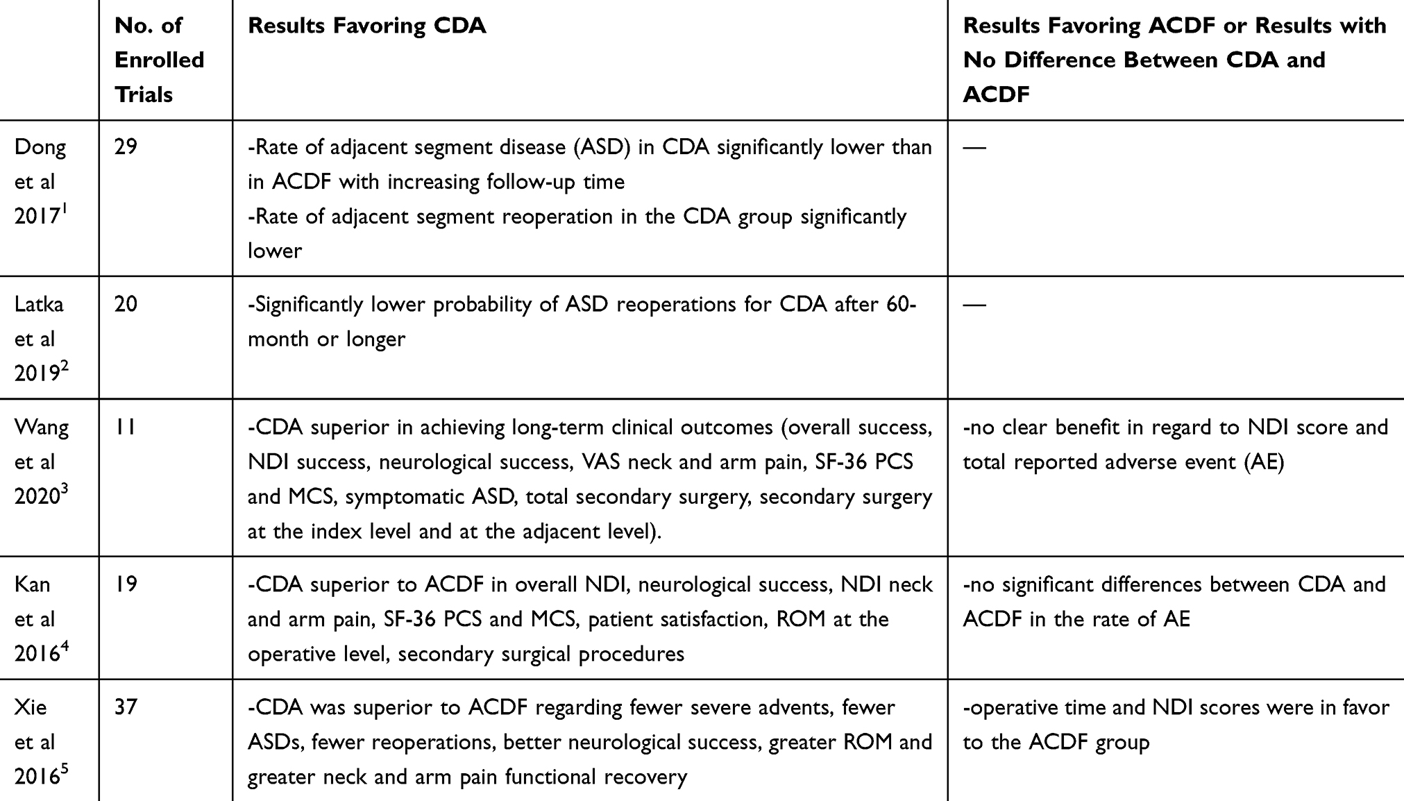 |
Table 1 Meta-Analyses Comparing Anterior Cervical Discectomy and Fusion (ACDF) with Cervical Disc Arthroplasty (CDA) |
According to these meta-analyses, CDA seems to be superior to ACDF in regard with most clinical parameters.
In view of these clinical results, it is not surprising that there are various CDA prostheses on the market today. They can be subdivided into two general design groups:
1. Cervical intervertebral disc prostheses with articulating surfaces (ball-and-socket design): The prostheses in this group are composed of at least two parts with articulating surfaces. These may both be made of metal. The Prestige LP® Cervical Disc (Medtronic, Minneapolis, Minnesota, USA) is an example for this metal-on-metal design group.6 Or one side is made of metal and the other is made of UHMWPE. An example of an implant with a fixed UHMWPE core is the Prodisc-C (Centinel Spine®, West Chester, Pennsylvania, USA).7 Other metal-on-UHMWPE implants have mobile cores, which allow some movement of the UHMWPE component against both endplates such as Mobi-C® (Zimmer-BioMet, Warsaw, Indiana, USA).8 These prostheses, however, do not allow for axial damping, and, thus, they are missing the natural degree of freedom in the axial direction. This may be a disadvantage since non-physiologic implant kinematics may be the consequence and high contact stresses can arise at the bone-end plate interface if they are improperly placed or undersized.9,10
2. Cervical intervertebral disc prostheses with a flexible core without articulating surfaces (so-called “next-generation” design): These prostheses have a flexible polymeric core, which is captured between the upper and lower endplates. Different sheaths protect this core and keep wear particles inside the implant. Examples for this group are the BRYAN® Cervical Disc (Medtronic, Minneapolis, Minnesota, USA) and the M6®-C cervical disc prosthesis (Spinal Kinetics, Sunnyvale, CA, USA).11,12 In single cases, failure of the sheaths was reported partially with a dislocation of the polyurethane core.13–16
The aim of the study is to provide design, material, and safety and performance data of the MOVE-C cervical disc prosthesis which combines characteristics of both design groups while avoiding UHMWPE and additional sheaths in order to minimize the risk of failure.
Materials and Methods
Implant Design
The cervical intervertebral disc prosthesis MOVE-C consists of a cranial and caudal metal plate made of TiAl6V4. The cranial plate is TiNbN coated on its inferior surface. The caudal plate has an injection-molded core made of polycarbonate-urethane (PCU) (Figure 1). This core is articulating with the TiNbN-coated surface of the cranial plate. Thus, from a purely geometrical point of view, the MOVE-C belongs to the ball-and-socket prosthesis design group. However, the PCU gliding surface makes it similar to the next generation cervical disc arthroplasty group, where flexible cores are used.
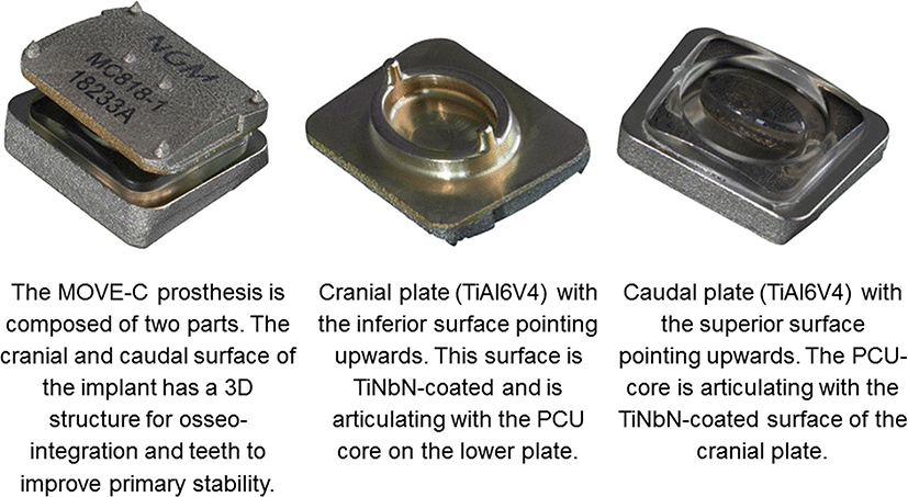 |
Figure 1 Design of the MOVE-C cervical intervertebral disc prosthesis. |
The plates themselves are additively manufactured and have a 3D structure towards the adjacent vertebral bodies to improve osseointegration. In order to ensure sufficient primary stability, the endplates are additionally equipped with teeth on the side facing the bone.
The design of the PCU core and the adjacent TiNbN-coated gliding surface is intended to allow a natural range of motion with a neutral zone and a progressive increase of resistance in all six degrees of freedom. In addition, the PCU core should absorb compressive loads in the axial direction. The force absorption is progressive due to the material characteristics of the PCU which is intended to result in a defined movement limitation but no hard stop.
Implant Materials
TiNbN-Coating
A strategy used to reduce wear of hard-on-soft joint replacement implants is to coat the metallic part with a hard layer such as TiN or TiNbN. The advantages claimed for TiNbN coatings are:
In vitro, the concentration of the metal ions released from TiNbN-coated femoral components was shown to be reduced compared to uncoated CoCrMo alloy substrates.17
Wettability, friction and wear resistance were investigated mostly on large joint replacement implants. For the knee joint, a clear loss of coating was shown in a wear simulator study, which was rising concerns related to the abrasion resistance of TiNbN coatings for this type of joint replacement.18,19 In hip and knee wear simulator studies the UHMWPE wear rate was shown to be similar if metallic TiNbN coated implant components were used as compared to ceramic and CoCr components.19–21 It was concluded that TiNbN coatings may be of special benefit to patients who are metal sensitive whereas the wear behavior of the TiNbN coating does not offer any additional benefit over standard materials such as ceramics and CoCr.
TiNbN was shown to be not cytotoxic.22 The attachment and biofilm formation of various bacteria was not significantly different between TiAl6V4 alloy coated with TiNbN and standard TiAl6V4 alloy materials or cobalt-chrome.23,24
In case of the MOVE-C implant, TiNbN was used to improve the wear behavior of the TiAl6V4 substrate. The aim was to combine the favorable osseointegration of titanium with a wear behavior which is comparable to that of CoCr or ceramics.
Polycarbonate Urethane (PCU) Core
PCU is used in a wide range of medical applications. The advantages claimed for this material are:
CoCr alloy, an AL2O3 ceramic, and polycarbonate urethane (PCU) were mechanically tested against human osteoarthritic cartilage. As a result, the friction coefficient tended to be smaller with PCU than with ceramic and both were smaller than CoCr.25
Acetabular hip joint components manufactured from gamma-sterilized UHMWPE, gamma cross-linked UHMWPE, and PCU polymers were evaluated in a hip joint simulator, using cobalt alloy femoral head components. The material loss for the PCU samples was at least 24% lower than for the cross-linked UHMWPE.26 The flexible and hydrophilic properties of PCU allow for a thick fluid film to develop, leading to a separation of the bearing surfaces with theoretical reduction in wear and lower friction. Tribological studies validated polyurethane cups to be low friction when compared to UHMWPE. The wear rates were reported to be below the described values for polyethylene cups.27
A comparison of the macrophage response to PCU and cross-linked UHMWPE in the presence or absence of endotoxin showed that cross-linked UHMWPE particles are potentially more proinflammatory to periprosthetic tissue than PCU.28 It was anticipated that the combination of larger wear particles, less reactivity and lower particle generation rate would make PCU of lower osteolytic risk compared to hard bearings in total hip replacement.27,29
The viscoelastic mechanical properties of medical grade polycarbonate urethane were assessed by Beckmann et al 2018.30 Unfortunately, there is no comparative data reported between PCU and the human disc, meaning that PCU behaves viscoelastically but the degree to which this behavior resembles the natural viscoelasticity of human tissue remains open.
PCU was shown to be a strong candidate for biostable medical devices.31 In an animal study the PCU Corethane 80A was used as the bearing layer in a prototype compliant layer acetabular cup, in an ovine total hip arthroplasty model. The authors showed that there was no significant evidence of biodegradation or wear damage after 3 years in vivo.32 However, because the oxidative stability of PUs is strongly dependent on the molecular structures and chemical formulations, findings may not be extrapolated to PCUs other than Bionate 80A.33
For the MOVE-C implant, PCU was chosen due to its viscoelasticity, allowing for a more natural degree of freedom in the axial direction and more natural three-dimensional, progressive load-deformation curves. Also, the wear behavior was something very important as the PCU core articulates with its TiNbN-coated counterpart.
Mechanical Performance
Creep Testing
Axial damping, creep and relaxation are physiological characteristics of the human intervertebral disc.34 In vivo, creep and relaxation are well balanced to enable nutrition of the intervertebral disc and to guarantee mechanical stability of the spinal column.
Since MOVE-C was meant to mimic this behavior, creep-relaxation tests were carried out. Six implants were placed in between two rigid metal test blocks and immersed in physiological saline solution at 37°C. A pushrod was used to apply an axial load to the implant.
The loading protocol was defined based on the current biomechanical literature to simulate the real in vivo creep and relaxation phases of the cervical spine (Table 2).35,36 During all loading phases, the axial load was applied sinusoidally at various frequencies to account for the cyclic axial load acting on the cervical spine in vivo.
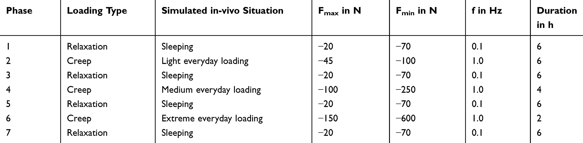 |
Table 2 Load Levels Defined for Creep Testing |
Testing showed a typical creep and relaxation behavior of the implants resulting in a mean permanent deformation of approximately 0.49 mm at the end of testing (Figure 2).
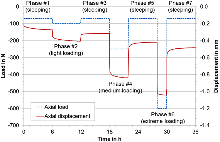 |
Figure 2 Mean displacement curves of all tested samples (red, solid line) with maximum load in N (blue dashed lines) during creep testing. |
Wear Testing
Wear testing was carried out in an MTS Spine Wear Simulator (Bionix ® Spine Wear Simulator, MTS Systems Corporation, Minnesota, USA) on n=6+1 samples according to ISO 18192–1:2011.37 According to this standard a sinusoidal axial load ranging between 50 and 150 N is applied simultaneously with sinusoidal rotations in all three planes. The amplitudes are ±7.5° for flexion-extension, ±6° for lateral bending, and ±4° for axial rotation. Testing was carried out until 15 million load cycles were reached.37
A gravimetric wear assessment was not possible since the implant could not reproducibly be cleaned. Therefore, sector field inductively coupled plasma mass spectrometry (ICP-SMS) was carried out on the fluid test medium of two samples to calculate the amount of titanium (coating and substrate), niobium (coating only), and vanadium (substrate only) wear in the test medium.38
ICP-SMS showed that the cumulative amount of Vanadium in the medium after 10 million load cycles was very small (less than 5 μg) and there was almost no difference between the loaded soak control station and the wear stations detectable.
The cumulative amount of titanium was much higher with values of 507 μg and 561 μg for the two samples, while the cumulative amount of Niobium was somewhere in between (160 μg and 163 μg) (Figure 3). In case of titanium and Niobium, which are both part of the coating, there was a significant difference between the loaded soak control station (Station 0) and the wear stations.
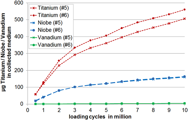 |
Figure 3 Cumulative mass of titanium, niobium and vanadium in the medium of implant no. 5 and 6 during standard wear testing. The results were derived from ICP-SMS. |
In summary, the results of the ICP-SMS showed that the total amount of metallic wear of Ti, Nb and V was below 1 mg after 10 million load cycles and seemed to derive from the coating (Titanium and Niobium) but almost not from the substrate (almost no Vanadium).
Additionally, the detailed analyses for the implants no. 5 and 6 showed that the initial wear rates per million cycles were higher than those towards the end of testing where an almost linear relationship between wear and number of cycles was shown.
The upper surface of the PCU components of the loaded soak control and of two representative test samples was scanned after 15 million load cycles using fringe projection (measurement uncertainty 15 μm).39 The volume of PCU material, which was worn off, was calculated for the two test samples by subtracting the surface of the loaded soak control specimen (Figure 4). Finally, the loss of volume was transformed into the PCU mass loss using the specific PCU density. The results revealed a total PCU mass loss of 23.04 mg for sample no. 5 and 20.64 mg for sample no. 6. This equals a mean wear rate of 1.54 and 1.38 mg/million load cycles.
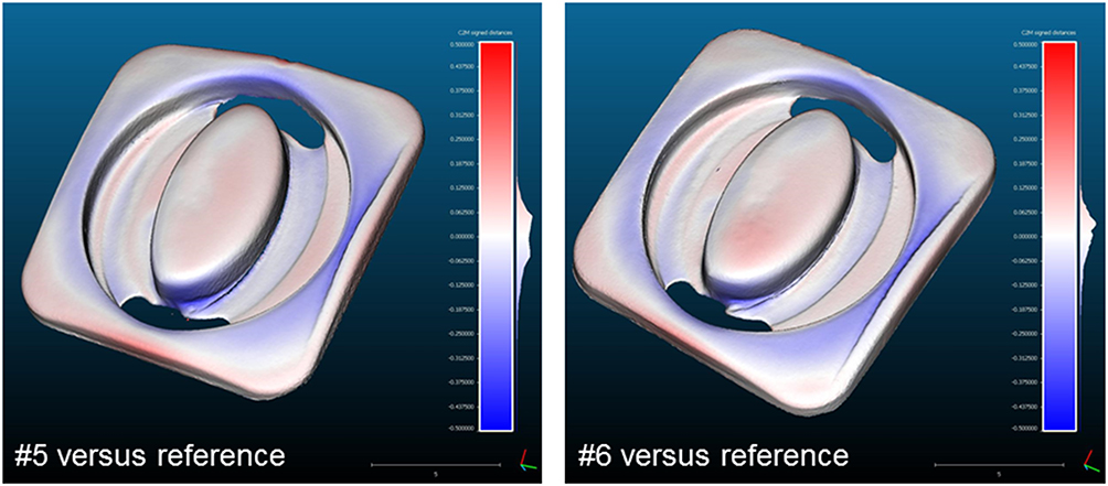 |
Figure 4 Surface analysis of the PCU component of implant no. 5 and implant no. 6 compared to that of station 0 (reference) after 15 million cycles of standard wear testing. These 3D scans were used to calculate the total PCU mass loss. |
The measurement uncertainty of this method is estimated to be approximately ±3.6 mg taking into account the possible sources of errors of the whole measurement chain.
Static and Dynamic Fatigue Testing
In addition to creep and wear testing, static and dynamic compression, static and dynamic compression-shear, static torsion, static expulsion and static subsidence tests were carried out.
Unfortunately, there are no comparative data available from other PCU cervical disc prostheses such as the M6-C or BRYAN® prostheses. Since the general mechanical safety requirements are the same of all types of cervical disc prostheses, a comparison with data from metal-on-UHMWPE implants was therefore carried out. For the Mobi-C and the Prodisc-C implants data was available from the FDA Summary of Safety and Effectiveness Data (SSED) files (Table 3).40,41
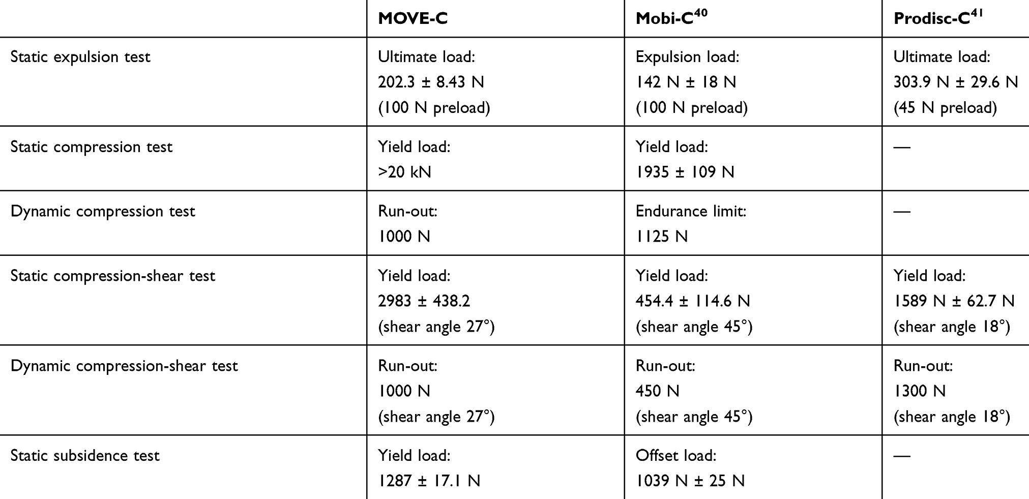 |
Table 3 Results of the Mechanical Testing of the Mobi-C and the Prodisc-C According to the FDA Summary of Safety and Effectiveness Data (SSED) Compared to Results of the MOVE-C |
The methodologies according to which the Mobi-C and the Prodisc-C implants were tested are only very briefly described in those SSEDs. Comparability between the results of non-standardized tests such as expulsion or luxation testing is therefore limited. However, the standard compression and compression shear tests as well as the subsidence test indicate that the results of the MOVE-C implant are mostly at least as good as the comparative values from Mobi-C and/or Prodisc-C.
Discussion
The present paper describes the design, materials and mechanical performance characteristics of the MOVE-C cervical intervertebral disc prosthesis. This prosthesis has a ball-and-socket design. However, in contrast to existing ball-and-socket disc prostheses, the MOVE-C incorporates a gliding surface made of PCU. This approach is new since, so far, PCU has only been used as an encapsulated core inside the implant such as for example the cores of the M6-C and BRYAN disc prostheses. Wear data therefore was of special interest.
Unfortunately, for cervical intervertebral disc prostheses with a PCU core, there has almost no mechanical test data been published so far. Only one study was available for comparison. According to that study, after 10 million cycles of wear testing, the BRYAN Total Cervical Disc prosthesis showed a relative mass loss of 1.76% compared to the implant’s mass before testing. Testing was carried out under flexion-extension and axial rotation only and under smaller loading amplitudes than those prescribed by the ISO 18192–1 standard.42 For comparison wear testing of the MOVE-C implant resulted in an overall loss of <0.5% of the initial implant mass after 10 million cycles of standard three-dimensional wear testing.
More data for cervical disc prostheses with PCU components were not found. Therefore, the results were additionally compared with those from metal-on-UHMWPE disc prostheses (Table 4). In this comparison, the absolute mass loss was smallest for a UHMWPE inlay articulating against Ti6Al4V with wear rate of 0.53 mg per million cycles after 10 million cycles of standard wear testing.43 The highest value was found for the Prodisc-C with 2.59 mg per million cycles.41 For comparison, the PCU wear rate for the MOVE-C was 1.54 respectively 1.38 mg per million cycles for the two implants were 3D surface scans were made.
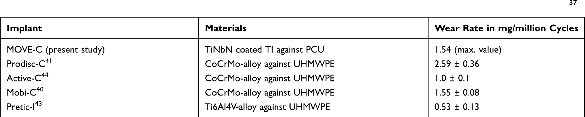 |
Table 4 Wear Rates for Various Intervertebral Disc Prostheses Under Standard Loading Conditions According to ISO 18192–137 |
In addition to the wear behavior, the behavior of the implant under axial load was of special interest since the PCU was claimed to simulate the real intervertebral disc in terms of its creep and axial damping characteristics. This was tested in a specially designed creep test, which was based on the real loading of the cervical spine. None of the MOVE-C implants failed during creep testing. The creep and relaxation curves showed the physiological J-shaped characteristic of the human disc.45 This proves the capability of the implant to recover after creep. The remaining loss of height after testing can mainly be attributed to the extreme loading of 600 N, which was applied in this test. In vivo, a loading magnitude of 600 N is expected to occur only sporadically. During testing, however, 600 N was applied for 7200 consecutive loading cycles, which simulates an extreme worst-case. Also, the relaxation phases were possibly not long enough to allow the implant to fully recover. Such an effect has also been described for the human intervertebral disc, where recovery was 3–4 times slower than loading.46,47
Also, very similar to the results of MOVE-C, a permanent deformation of 0.47 mm was reported for the Prodisc-C implant.41 However, the loading protocol was a bit different with an incorporated shear angle of 18° to the horizontal, other load levels and phasings. But still, this protocol was also developed to simulate the situation in vivo. For the Prodisc-C it was concluded that failure due to creep is unlikely. Other comparative data was not found since most studies are carried out on animal discs and the loading protocols are very different.
Conclusion
In conclusion, the mechanical safety and performance of the MOVE-C cervical intervertebral disc prosthesis was shown to be comparable to other cervical disc prostheses. In contrast to conventional metal-on-UHMWPE implants, the flexible PCU-core was shown to allow for axial displacement, and, thus, for a more realistic motion pattern as compared to metal-on-UHMWPE implants. The clinical impact of these mechanical findings as well as of other advantages claimed for the new metal-on-PCU design of the MOVE-C implant such as the more physiological neutral zone and the progressive load deformation curves in all anatomical planes will have to be investigated in further studies.
Acknowledgments
This research was funded by NGMedical. NGMedical supports mechanical tests, literature search and mscientific writing at SpineServ. We would like to thank the Laboratory of Biomechanics and Implant Research, Department of Orthopaedics & Trauma Surgery, Heidelberg University Hospital, Germany for the realization of the ICP-SMS and the Institute of Laser Technologies in Medicine and Metrology at the University of Ulm, Germany for preforming the 3D surface scans.
Disclosure
The authors report no conflicts of interest in this work.
References
1. Dong L, Xu Z, Chen X, et al. The change of adjacent segment after cervical disc arthroplasty compared with anterior cervical discectomy and fusion: a meta-analysis of randomized controlled trials. Spine J. 2017;10(10):1549–1558. doi:10.1016/j.spinee.2017.06.010
2. Latka D, Kozlowska K, Miekisiak G, et al. Safety and efficacy of cervical disc arthroplasty in preventing the adjacent segment disease: a meta-analysis of mid- to long-term outcomes in prospective, randomized, controlled multicenter studies. Ther Clin Risk Manag. 2019;Volume 15:531–539. doi:10.2147/TCRM.S196349
3. Wang Q-L, Tu Z-M, Hu P, et al. Long-term results comparing cervical disc arthroplasty to anterior cervical discectomy and fusion: a systematic review and meta-analysis of randomized controlled trials. Orthop Surg. 2020;1(1):16–30. doi:10.1111/os.12585
4. Kan S-L, Yuan Z-F, Ning G-Z, Liu -F-F, Sun J-C, Feng S-Q. Cervical disc arthroplasty for symptomatic cervical disc disease: traditional and Bayesian meta-analysis with trial sequential analysis. Int J Surg. 2016;35:111–119. doi:10.1016/j.ijsu.2016.09.088
5. Xie L, Liu M, Ding F, Li P, Ma D. Cervical disc arthroplasty (CDA) versus anterior cervical discectomy and fusion (ACDF) in symptomatic cervical degenerative disc diseases (CDDDs): an updated meta-analysis of prospective randomized controlled trials (RCTs). SpringerPlus. 2016;1(1):1188. doi:10.1186/s40064-016-2851-8
6. Gornet MF, Lanman TH, Burkus JK, et al. Cervical disc arthroplasty with the prestige LP disc versus anterior cervical discectomy and fusion, at 2 levels: results of a prospective, multicenter randomized controlled clinical trial at 24 months. J Neurosurg Spine. 2017;6(6):653–667. doi:10.3171/2016.10.SPINE16264
7. Choi H, Purushothaman Y, Baisden J, Yoganandan N. Unique biomechanical signatures of bryan, prodisc C, and prestige LP cervical disc replacements: a finite element modelling study. Eur Spine J. 2019. doi:10.1007/s00586-019-06113-y
8. Pham M, Phan K, Teng I, Mobbs RJ. Comparative study between M6-C and mobi-C cervical artificial disc replacement: biomechanical outcomes and comparison with normative data. Orthop Surg. 2018;2(2):84–88. doi:10.1111/os.12376
9. Lin C-Y, Kang H, Rouleau JP, Hollister SJ, La Marca F. Stress analysis of the interface between cervical vertebrae end plates and the bryan, prestige LP, and prodisc-C cervical disc prostheses: an in vivo image-based finite element study. Spine. 2009;15(15):1554. doi:10.1097/BRS.0b013e3181aa643b
10. Patwardhan AG, Havey RM. Prosthesis design influences segmental contribution to total cervical motion after cervical disc arthroplasty. Eur Spine J. 2019. doi:10.1007/s00586-019-06064-4
11. Lauryssen C, Coric D, Dimmig T, Musante D, Ohnmeiss DD, Stubbs HA. Cervical total disc replacement using a novel compressible prosthesis: results from a prospective food and drug administration-regulated feasibility study with 24-month follow-up. Int J Spine Surg. 2012;6(1):71–77. doi:10.1016/j.ijsp.2012.02.001
12. Wenger M, Markwalder T-M. Bryan total disc arthroplasty: a replacement disc for cervical disc disease. Med Devices (Auckl). 2010;11–24.
13. Baltus C, Costa E, Vaz G, Raftopoulos C. Granulomatous reaction on a double-level cervical total disc arthroplasty. World Neurosurg. 2019;122:360–363. doi:10.1016/j.wneu.2018.11.070
14. Brenke C, Schmieder K, Barth M. Core herniation after implantation of a cervical artificial disc: case report. Eur Spine J. 2015;24(S4):S536–9. doi:10.1007/s00586-014-3677-0
15. Xia M-AM, Winder MJ. M6-C cervical disc replacement failure associated with late onset infection. J Spine Surg. 2019;4(4):584–588. doi:10.21037/jss.2019.11.06
16. Fan H, Wu S, Wu Z, Wang Z, Guo Z. Implant failure of Bryan cervical disc due to broken polyurethane sheath: a case report. Spine. 2012;13(13):E814–6. doi:10.1097/BRS.0b013e3182477d85
17. Ragone V, Canciani E, Biffi CA, et al. CoCrMo alloys ions release behavior by TiNbN coating: an in vitro study. Biomed Microdevices. 2019;3(3):61. doi:10.1007/s10544-019-0417-6
18. Haider H, Weisenburger JN, Croson RE, Namavar F, Garvin KL. Concern with adhesion and wear of a titanium niobium nitride coating on total knee replacements for metal sensitive patients.
19. Gotman I, Gutmanas EY, Hunter G. 1.8 Wear-resistant ceramic films and coatings. In: Ducheyne P, editor. Comprehensive Biomaterials II. Oxford: Elsevier; 2017:165–203.
20. Fabry C, Zietz C, Baumann A, Bader R. Wear performance of sequentially cross-linked polyethylene inserts against ion-treated CoCr, TiNbN-coated CoCr and Al2O3 ceramic femoral heads for total hip replacement. Lubricants. 2015;1(1):14–26. doi:10.3390/lubricants3010014
21. Malikian R, Maruthainar K, Stammers J, Wilding CP, Blunn GW. Four Station Knee Simulator Wear Testing Comparing Titanium Niobium Nitride with Cobalt Chrome. 2013.
22. Serro AP, Completo C, Colaço R, et al. A comparative study of titanium nitrides, TiN, TiNbN and TiCN, as coatings for biomedical applications. Surf Coat Technol. 2009;24(24):3701–3707. doi:10.1016/j.surfcoat.2009.06.010
23. Allyn G, Bloebaum RD, Epperson RT, Nielsen MB, Dodd KA, Williams DL. Ability of a wash regimen to remove biofilm from the exposed surface of materials used in osseointegrated implants. J Orthop Res. 2019;1(1):248–257. doi:10.1002/jor.24161
24. Bidossi A, Bottagisio M, De Grandi R, De Vecchi E. Ability of adhesion and biofilm formation of pathogens of periprosthetic joint infections on titanium-niobium nitride (TiNbN) ceramic coatings. J Orthop Surg Res. 2020;1(1):90. doi:10.1186/s13018-020-01613-w
25. Ajdari N, Tempelaere C, Masouleh MI, et al. Hemiarthroplasties: the choice of prosthetic material causes different levels of damage in the articular cartilage. J Shoulder Elbow Surg. 2020;5(5):1019–1029. doi:10.1016/j.jse.2019.09.041
26. St John K, Gupta M. Evaluation of the wear performance of a polycarbonate-urethane acetabular component in a hip joint simulator and comparison with UHMWPE and cross-linked UHMWPE. J Biomater Appl. 2012;1(1):55–65. doi:10.1177/0885328210394471
27. Grieco PW, Pascal S, Newman JM, et al. New alternate bearing surfaces in total hip arthroplasty: a review of the current literature. J Clin Orthop Trauma. 2018;1(1):7–16. doi:10.1016/j.jcot.2017.10.013
28. Smith RA, Hallab NJ. In vitro macrophage response to polyethylene and polycarbonate-urethane particles. J Biomed Mater Res A. 2010;1:347–355.
29. Eliaz N. Corrosion of metallic biomaterials: a review. Materials. 2019;3.
30. Beckmann A, Heider Y, Stoffel M, Markert B. Assessment of the viscoelastic mechanical properties of polycarbonate urethane for medical devices. J Mech Behav Biomed Mater. 2018;82:1–8. doi:10.1016/j.jmbbm.2018.02.015
31. Dempsey DK, Carranza C, Chawla CP, et al. Comparative analysis of in vitro oxidative degradation of poly(carbonate urethanes) for biostability screening. J Biomed Mater Res A. 2014;10(10):3649–3665. doi:10.1002/jbm.a.35037
32. Khan I, Smith N, Jones E, Finch DS, Cameron RE. Analysis and evaluation of a biomedical polycarbonate urethane tested in an in vitro study and an ovine arthroplasty model. Part II: in vivo investigation. Biomaterials. 2005;6(6):633–643. doi:10.1016/j.biomaterials.2004.02.064
33. Kurtz SM, Siskey R, Reitman M. Accelerated aging, natural aging, and small punch testing of gamma-air sterilized polycarbonate urethane acetabular components. J Biomed Mater Res B Appl Biomater. 2010;2(2):442–447. doi:10.1002/jbm.b.31601
34. Araujo ARG, Peixinho N, Pinho ACM, Claro JCP. Quasi-static and dynamic properties of the intervertebral disc: experimental study and model parameter determination for the porcine lumbar motion segment. Acta Bioeng Biomech. 2015;4.
35. Bernhardt P, Wilke H-J, Wenger KH, Jungkunz B, Böhm A, Claes LE. Multiple muscle force simulation in axial rotation of the cervical spine. Clin Biomech. 1999;1(1):32–40. doi:10.1016/S0268-0033(98)00031-X
36. Walker LB, Harris EH, Pontius UR. Mass, Volume, Center of Mass, and Mass Moment of Inertia of Head and Head and Neck of Human Body. 1973.
37. ISO 18192–1. Implants for Surgery — Wear of Total Intervertebral Spinal Disc Prostheses — Part Loading and Displacement Parameters for Wear Testing and Corresponding Environmental Conditions for Test. 2008. 1–32.
38. Krachler M, Heisel C, Philippe Kretzer J. Validation of ultratrace analysis of Co, Cr, Mo and Ni in whole blood, serum and urine using ICP-SMS. J Anal at Spectrom. 2009;5(5):605. doi:10.1039/b821913c
39. Nothelfer S, Bergmann F, Liemert A, Reitzle D, Kienle A. Spatial frequency domain imaging using an analytical model for separation of surface and volume scattering. J Biomed Opt. 2018;7(07):1–10. doi:10.1117/1.JBO.24.7.071604
40. FDA. Mobi-C® cervical disc prosthesis. Summary Saf Effect Data. 2013:P110002.
41. FDA. ProDisc™-C total disc replacement. Summary Saf Effect Data. 2007:P070001.
42. Anderson PA, Rouleau JP, Bryan VE, Carlson CS. Wear analysis of the Bryan cervical disc prosthesis. Spine. 2003;20(Supplement):S186–94. doi:10.1097/01.BRS.0000092212.42388.79
43. Wu W, Lyu J, Liu H, et al. Wear assessments of a new cervical spinal disk prosthesis: influence of loading and kinematic patterns during in vitro wear simulation. Proc Inst Mech Eng H. 2015;9(9):619–628. doi:10.1177/0954411915594829
44. Grupp TM, Meisel H-J, Cotton JA, et al. Alternative bearing materials for intervertebral disc arthroplasty. Biomaterials. 2010;3(3):523–531. doi:10.1016/j.biomaterials.2009.09.064
45. Gloria A, Causa F, De Santis R, Netti PA, Ambrosio L. Dynamic-mechanical properties of a novel composite intervertebral disc prosthesis. J Mater Sci Mater Med. 2007;11(11):2159–2165. doi:10.1007/s10856-007-3003-z
46. van der Veen AJ, Mullender MG, Kingma I, van Dieen JH, Smit TH. Contribution of vertebral corrected bodies, endplates, and intervertebral discs to the compression creep of spinal motion segments. J Biomech. 2008;6(6):1260–1268. doi:10.1016/j.jbiomech.2008.01.010
47. O’Connell GD, Jacobs NT, Sen S, Vresilovic EJ, Elliott DM. Axial creep loading and unloaded recovery of the human intervertebral disc and the effect of degeneration. J Mech Behav Biomed Mater. 2011;7(7):933–942. doi:10.1016/j.jmbbm.2011.02.002
 © 2020 The Author(s). This work is published and licensed by Dove Medical Press Limited. The full terms of this license are available at https://www.dovepress.com/terms.php and incorporate the Creative Commons Attribution - Non Commercial (unported, v3.0) License.
By accessing the work you hereby accept the Terms. Non-commercial uses of the work are permitted without any further permission from Dove Medical Press Limited, provided the work is properly attributed. For permission for commercial use of this work, please see paragraphs 4.2 and 5 of our Terms.
© 2020 The Author(s). This work is published and licensed by Dove Medical Press Limited. The full terms of this license are available at https://www.dovepress.com/terms.php and incorporate the Creative Commons Attribution - Non Commercial (unported, v3.0) License.
By accessing the work you hereby accept the Terms. Non-commercial uses of the work are permitted without any further permission from Dove Medical Press Limited, provided the work is properly attributed. For permission for commercial use of this work, please see paragraphs 4.2 and 5 of our Terms.