")
Back to Journals » Cancer Management and Research » Volume 12
The Measurement of the Air-Kerma Rate in Air and a Solid Phantom with Ionization Chambers for a 192Ir HDR Brachytherapy Source
Authors Zeng J, Qu P, Pang Q, Wang P
Received 4 August 2020
Accepted for publication 9 October 2020
Published 29 October 2020 Volume 2020:12 Pages 10821—10828
DOI https://doi.org/10.2147/CMAR.S275378
Checked for plagiarism Yes
Review by Single anonymous peer review
Peer reviewer comments 5
Editor who approved publication: Dr Eileen O'Reilly
Jing Zeng,1,2 Pengpeng Qu,1 Qingsong Pang,2 Ping Wang2
1Department of Gynecologic Oncology, Tianjin Central Hospital of Gynecology and Obstetrics, Affiliated Hospital of Nankai University, Tianjin 300100, People’s Republic of China; 2Tianjin Medical University Cancer Institute and Hospital, National Clinical Research Center for Cancer, Key Laboratory of Cancer Prevention and Therapy, Tianjin’s Clinical Research Center for Cancer, Tianjin 300060, People’s Republic of China
Correspondence: Pengpeng Qu Email [email protected]
Introduction: This study aims to measure the air-kerma rate of 192-Ir-HDR-afterloading source with an ionization chamber in air and a solid cylindrical phantom separately and to compare the dose calibration by the American Association of Physicists in Medicine (AAPM) Task Group TG-43U1 formalism with the Abacus treatment planning system (TPS).
Materials and Methods: The air-kerma rate of 192Ir source was measured by an ionization chamber in air and a solid cylindrical phantom separately. For the interesting point position P (8cm, 90°), the values of the dose were calculated with the TG-43U1 formula and compared with data from the Abacus TPS with single and multiple dwell positions, respectively.
Results: The air-kerma rate percentage deviations between the detector measurements in air and the source certificate were − 1.28%, − 0.91%, − 0.71%, and 0.33% at the distances of 25cm, 50cm, 75cm, and 100cm, respectively. For the measurement in solid cylindrical phantom, the percent deviation from the air-kerma rate certificate was 1.85%. The percentage deviations of the dose calibration between Abacus TPS and TG-43U1 formalism at P (8cm, 90°) were − 2.30%, 1.76%, and 2.10% with different distances (between the dwell positions) of 0cm, 0.5cm, and 1cm, respectively.
Conclusion: The in-air technique was a new attempt for clinic routine measurement. Further studies are still necessary. As a treatment planning system, the Abacus TPS should apply the AAPM TG-43U1 formulism for the development required in the future.
Keywords: brachytherapy, 192Ir source, calibration, ionization chamber
Introduction
High dose rate (HDR) remote afterloading brachytherapy is an effective treatment modality for cancer.1 In the treatment modality, the dosimetric characteristics of the source should be determined to provide reliable data for use in treatment planning calculations and dose prescription.2 It is necessary to verify the half-life and the air-kerma rate quoted in both treatment planning system (TPS) and microprocessors controlling treatment delivery to ensure the same decay calculations for multiple fractions and consistent treatments.2
Typically, the TPS has its standard algorithms, modifications, and data handled. Taking Abacus TPS, for example, it has a transparent and open system where the users can edit the data. This system also includes different types of radioactive source models and applicators. The American Association of Physicists in Medicine (AAPM) Task Group TG43 and TG43U1 provides the dose calculation formalism and factors of different sources applied in clinical practice.2 Recently, many TPS algorithms base their calculations on the TG-43 formalism. Except for the suitable calibration standards, the accuracy and precision of the dose measurement with conventional dosimeters are also important. The dosimetry company (PTW Freiburg) supplies the user with a calibration factor for a standard ionization chamber (PTW Ionizing radiation Detectors 2008/2009) to measure the dose to water. Report 13 of the Deutsche Gesellschaft für Medizinische Physik (DGMP 1999a) supports the measurement procedures for the strength of brachytherapy in calibration facility.3,4
In this article, we presented the practice of measuring 192Ir HDR source (GammaMed Plus HDR 192Ir 0.9mm, MDS Nordion Haan GmbH, Germany) with the 1.0cm3 Rigid Stem Chamber (TM23331, PTW) in air and a solid cylindrical phantom separately. And we verified the dose calculations at the interesting point position P (8cm, 90°) by the Abacus TPS with single and multiple dwell positions of 192Ir HDR source with the TG43U1 formalism.
Materials and Methods
Radioactive Check
AAPM’s TG-51 protocol recommended air temperature correction and constancy check of dosimeters.5 They enabled medical physicists to check the stability of the ionization chamber response and to determine air temperature correction factors. The chamber calibration certificate included the reference reading under standard conditions. The check reading would decrease over time due to the decay of the activity.
In-Air Calibration
We designed an apparatus for free-air measurement,6 shown in Figure 1. The 192Ir source with the applicator (the thickness of 0.28 mm in steel) and the ionization chamber were located by a corresponding bracket released in the air in different intervals with the reference distances of 25cm, 50cm, 75cm, and 100cm. The electrometer, UNIDOS webline (T10021-0047, PTW Freiburg GmbH, Germany), had a conjunction with the 1.0cm3 Rigid Stem Chamber (TM23331, PTW) to measure the chamber current. The applicator, including the source, was parallel to the ionization chamber with a 60Co buildup-cap, as shown in Figure 2.
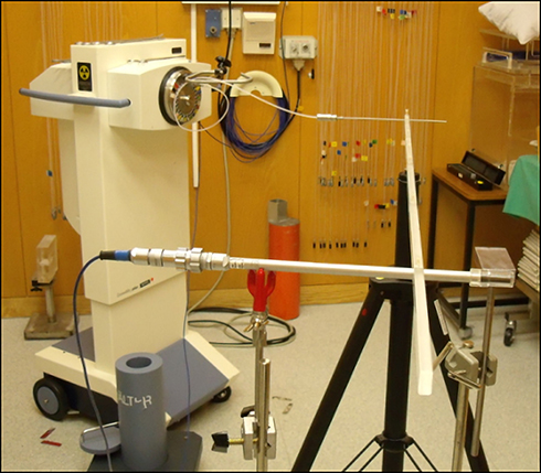 |
Figure 1 Paradigm of the free-air measurement. |
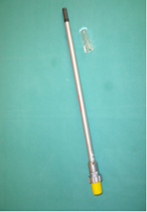 |
Figure 2 1.0cm3 rigid stem chamber and 60Co buildup-cap. |
Firstly, we located the ionization chamber with a 60Co buildup-cap with reference distances of 25cm, 50cm, 75cm, and 100cm from the source without shielding material near the chamber. MT was the direct gamma-ray from the source and the scattering radiation from the room in the measurement condition.7 Secondly, we repeated the measurements with a shield directly near the chamber. MS was the scattering radiation of the environment background due to the lead shielding the gamma-ray from the source to the chamber directly. The shielding material was lead in cuboids with a length of 7cm and a width of 5cm8 to make the broad beam transmission of 192Ir sources through lead less than 0.031%.9,10 Finally, we repeated the above measurements in the absence of a radioactive source. MOffset was the disturbance of the environment background. All measurements were carried out in the same position in the room and repeated ten times.
Because the manufacturer PTW provided the chamber calibration factor for water energy doses, the formula for the air-kerma rate calibration of the compact chamber was from the Report 13 of the Deutsche Gesellschaft für Medizinische Physik (DGMP 1999a) as follows:3
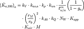
where kV was the correction for the spatial extent of the probe. kas, a was the correction for attenuation and scattering of radiation in the surrounding material air.  was the correction factor for the air temperature and pressure. kwa was the correction for the transition from water to the surrounding material air.
  was the ratio of the mass-energy absorption coefficients for water and air, averaged over the energy distribution at the measuring point for 192Ir source ((μen/μ) w/(μen/μ) a). ga was the Bremsstrahlung losses relative to air for 192Ir radiation. rM was the measurement distance. r0 was the reference interval for the air-kerma dose rate specification (100cm). KAK was the correction for 60Co buildup-cap. kQ, was the correction for the 60Co deviating radiation quality from the manufacture certificate (possibly by interpolating the response factor of 60Co and X-rays of the highest quality).3 NW was the calibration factor for the water-energy dose of 60Co source (mGy/C).11 The chamber calibration certificate provided the value of NW. Kapp was the correction for the source applicator with a thickness of 0.28 mm in steel (According to the Tenth value layer (TVL)2 of 192Ir in steel was 4.3cm and formula
  ). Kair was the correction for linear attenuation in the air as a medium. (According to the linear attenuation coefficient2 μ of air was 0.00012cm−1 with a density of 0.0013 g/cm3,
 where rM was the measurement distances of 25cm, 50cm, 75cm, and 100cm.) M was the measurement result. The values of the factors in Equation (1) are shown in Table 1.
 |
Table 1 The Values of the Factors in Equation (1) |
In-Solid Phantom Calibration
The air-kerma rate was measured by the 1.0cm3 Rigid Stem Chamber (TM23331, PTW) with the electrometer UNIDOS webline T10021-0047 in AL calibration phantom T9193 offered by the PTW Company (Freiburg, Germany). The solid cylindrical phantom consisted of a PMMA (acrylic) cylinder with a diameter of 20cm and a height of 12cm, with an atomic ratio of 2:1 for H: O and ρ = 0.998 g/cm3. The applicator with source was in the center of the phantom, and an array of detector ring was in this phantom at polar angles 0°, 90°, 180°, and 270° and at radial distances of r =8cm. The phantom was placed on a tripod with a minimum distance of 60cm to walls and floor to avoid backscattering.
The formula for the air-kerma rate in water with an ionization chamber taken from Report 13 of the Deutsche Gesellschaft für Medizinische Physik (DGMP 1999a) was:3
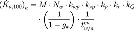
M was the indicated value of the dosimeter (C/h). Nw was the calibration factor for the water-energy dose of 60Co source (mGy/C) as the same in Equation (1). Kwp was the field disturbance correction factor for the transfer from water to PMMA phantom (Kwp≈1). kzp was the geometry factor of cylinder phantom, taking into account the attenuation and scattering of the radiation in-cylinder phantom. The value of the volume correction for the ionization chamber M23331 in distance 8cm was 1.187±0.012. kr was the correction factor for the measuring point with the square of the measuring distance of 8cm (between the reference point of the source and the measuring point) divided by the reference distance 100cm: kr = (8/100)2 = 0.0064. kp was the correction factor for the air temperature and the pressure as the same in Equation (1). kQ was the correction for the 60Co deviating radiation quality from the manufacture certificate as the same in Equation (1). gw was the fraction of the initial kinetic energies of secondary particles released in water as Bremsstrahlung for 192Ir radiation: gw = 0.001. And  was the ratio of the mass-energy absorption coefficients for water and air, averaged over the energy distribution at the measuring point as the same in Equation (1).
Simulation of Dose Distribution by Abacus TPS
The Abacus TPS (Program Version 3.1, Isotopen-Technik Dr. Sauerwein GmBH) provided the dose calculation method based on point source approximation, including Sievert integral and the Meisberger polynomial. The dose rate was calculated by multiplying the Meisberger polynomial with source activity, exposure rate per activity measured in air, and anisotropy factor as a function of distance and angle (r, θ) between the source and the point of interest.
The Meisberger polynomial described the effects of absorption and scattering caused by photons at certain distances. Different irradiation settings could be created by varying the number of dwell positions, the irradiation time for each dwell position, and the distance between two dwell positions for each applicator.
In our research, we calculated the dose distribution at 8cm by the Abacus TPS. The treatment time was 999 s for a single source at the dwell position. The dose depth was 8cm from the source dwell position with an angle of 90° referring to the source longitudinal axis. Because the Abacus TPS only retained two decimal places. The treatment time of 999s was transformed into 100s by multiplying with the coefficient (100/999) to make the counting more precise. As a clinical practice with the single uterine tandem, the irradiation scenarios for a 5cm long source were created in the TPS with 11 dwell positions (the distances between the dwell positions were 0.5cm) and six dwell positions (the distances between the dwell positions were 1cm), respectively. The measurement time was 999 s at each dwell position and then transformed into a time of 100 s. The dose depth was 8cm from the first dwell position with an angle of 90° referred to the source longitudinal axis.
The TG-43U1 formula was based on the dosimetric parameters used to calculate the absolute dose around the source, such as the air-kerma rate (SK), dose rate constant (Λ), geometric factor GX(r, θ), radial dose function gX(r) and two-dimensional (two-dimensional) anisotropy factor.
Results
Radioactive Check
As for making radioactive check, the 1.0cm3 Rigid Stem Chamber was located in the radioactive check device in radioactive check time t = 60 s and the check reading was M = 1.105 nC = 6.63*10−8 C/h. Under the measurement conditions: t = 23.9 °C,p = 962.1 hPa, according to the chamber calibration certificate: Nw = 2.998*107 Gy/C,kp,0 = 3.586*10−2 Gy/min. The result of measurement was k’p,0 = M*Nw = 6.63*10−8 *60C/min*2.998*107Gy/C = 3.313*10−2 Gy/min on the measurement date.
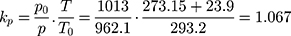
Since the check reading will decrease over time due to the decay of the activity, the factor kp,0 can be calculated at different times by the radioactive decay rates. From the information of the chamber calibration certificate, the decay factor of kp,0 was 0.985348 on the measurement date. The standard value of kp,0 = 3.586*10−2Gy/min*0.985348 = 3.533*10−2 Gy/min. kp = kp,0/k’p,0 = 3.533*10−2/3.313*10−2 = 1.066. According to the measurement conditions t = 23.9 °C, p = 962.1 hPa
The percent deviation from the check reading standard was about 0.09%.
In-Air Calibration
As for the radiation source of 192Ir used in this practice, the air-kerma rate at 1m was 51.157 mGy/h on the date of the certification provided by the MDS Nordion company. According to the law of radioactive decay, the decay of 192Ir could be calculated. The air-kerma rate from the source certificate was 22.8167mGy/h by calculation on the test date.
The measurement result was equal to M = MT -MS -MOffset. According to Equation (1), the mean values of the air-kerma rate ((Ka,100)a) were 22.5254 mGy/h, 22.6102 mGy/h, 22.6544 mGy/h, and 22.8931 mGy/h at the distances 25cm, 50cm, 75cm, and 100cm, respectively, as given in Table 2.
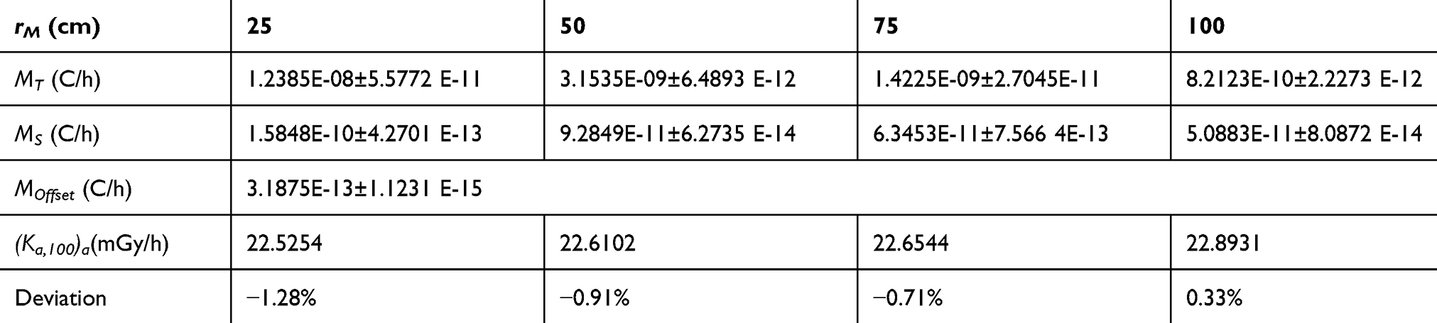 |
Table 2 The Mean Value of the Measurements and the Calculation of the Air-Kerma Rate at Different Distances with Measurement Time t = 100*1.79 = 179 s |
The air-kerma rate percentage deviations between the detector measurements and the source certificate are −1.28%, −0.91%, −0.71%, and 0.33% at the distances 25cm, 50cm, 75cm, and 100cm, respectively.
In-Solid Phantom Calibration
We repeated the measurements ten times in the same position in the room. The mean value of the dosimeter M was 9.5173*10−10±4.2631 *10−12C/h. According to the DGMP Report-13 Equation (2), the mean value of the air-kerma rate ((Ka,100)a) was 20.8363 mGy/h. The air-kerma rate percentage deviation between the detector measurement and the source certificate was 1.85%.
Simulation of Dose Distribution by Abacus TPS
As shown in Figure 3, the value of the dose by Abacus TPS was 1.88 Gy for 999 s, which equals 0.1882 Gy for 100 s by multiplying with the coefficient (100/999). The percent deviation was −2.30%, compared with the value from the calibration TG-43U1 standard 0.1840 Gy.
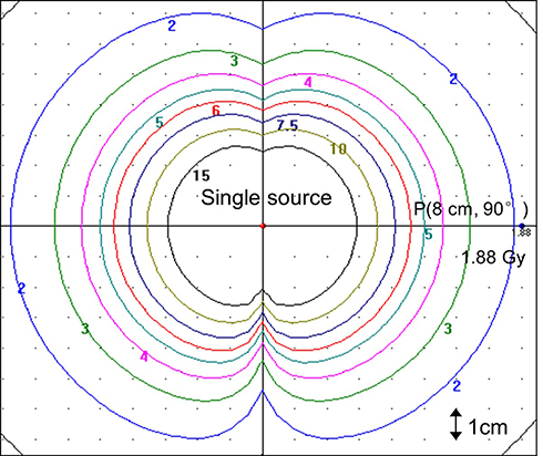 |
Figure 3 Calculation of 2D dose distribution with single source by Abacus TPS. |
As shown in Figure 4, the distances between the dwell positions were 0.5cm. The dose at the interesting point position P (8cm, 90°) was 18.24 Gy for 999 s. It was 1.825826 Gy for 100 s by multiplying with the coefficient (100/999). The dose calculated by TG-43U1 formula was 1.8588 Gy.
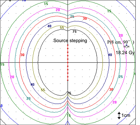 |
Figure 4 Calculation of 2D dose distribution with source dwell distance of 0.5cm by Abacus TPS. |
When the distances between the dwell positions were 1cm, the dose at the interesting point P (8cm, 90°) was 9.89 Gy for 999 s, as shown in Figure 5. It was 0.98999 Gy for100 s by multiplying the coefficient (100/999). The dose calculated by TG-43U1 formula was 1.0112 Gy.
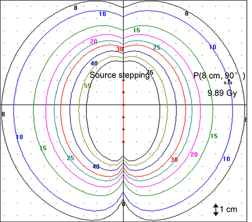 |
Figure 5 Calculation of 2D dose distribution with source dwell distance of 1cm by Abacus TPS. |
As shown in Table 3, the percentage deviations of the dose calibration between Abacus TPS and TG-43U1 formalism at P (8cm, 90°) were −2.30%, 1.76%, and 2.10% with the distances (between the dwell positions) of 0cm, 0.5cm, and 1cm, respectively.
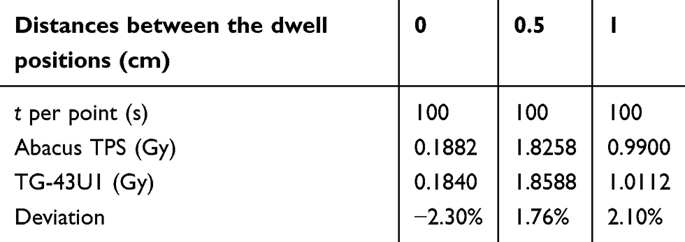 |
Table 3 Dose Calculation by Abacus TPS Verified with TG-43U1 at P (8cm, 90°) |
Discussion
The aim of calibrating the brachytherapy source was to ensure that the value of dose entering into the treatment planning system agrees with the source calibration certificate. And the dose calculation accuracy should be verified.12
From the results of the measurement by in-air measurement technique, the air-kerma rate percentage deviations between the detector measurements and the source certificate are −1.28%, −0.91%, −0.71%, and 0.33% at the distances 25cm, 50cm, 75cm, and 100cm, respectively. During the measurement process, the results of offset have large fluctuations that may yield large uncertainties in the source calibration. Furthermore, the low dose rates (low signal for the detector) may decrease the preciseness of the measurement. For these reasons, a direct measure of the air-kerma rate in 100cm distance, which was inconclusive, was only a new attempt for the routine measurement in clinical practice. On the other hand, the percentage deviation of air-kerma rate measurement from the certificate was small, up to 1.85%, by solid phantom measure, which was usually used for the source strength measurement in clinical practice.
The uterine tandem with an open-ended vaginal cylinder was the most commonly used brachytherapy system for patients with cervical cancer in Asian.13 In clinical practice, treatment plans were generated with a single tandem line source with a vaginal cylinder applicator. And it was modified by the Abacus TPS. Our experiment compared dose calibration at the interesting point with a single dwell position and a 5cm long source with the distances (between the dwell positions) of 0.5cm and 1cm, respectively. The percentage deviations of the dose calibration between Abacus TPS and TG-43U1 formalism at P (8cm, 90°) were −2.30%, 1.76%, and 2.10% with the distances (between the dwell positions) of 0cm, 0.5cm, and 1cm, respectively. Shwetha et al14 calculated similar dose differences, up to 1.88%, along the perpendicular axis of the source. They observed that the absorbed dose D (r, θ) strongly depends on the radial distance r and the angle between the source center and the point of interest. Hediye et al15 calculated the dose rate profiles of a 192Ir source by the Monte Carlo technique (MCNP) and compared the dose rate values with those calculated by the Abacus TPS. They also found similar discrepancies between TPS and MCNP at the points (lying along the source axis), which have large theta (θ) angles between the source center and the interesting point. The difference between TPS and MC along the source axis may be caused by the anisotropy factor used in the TPS algorithm. At the same time, MCNP calculates the dose by considering radiation interaction.
Besides, the uncertainties of our research were evaluated by the manufacturer’s specifications. And the measurement background was concerned. The uncertainty of the source measurement may come from the temperature and pressure, electrometer, ionization chamber, measurement values, primary calibration of the ionization chamber, and measurement settings.16
Finally, there were several limitations to the present study. Since the manufacturer, PTW provided the chamber calibration factor for water energy doses, and the formula was an old version in our practices, the value of kQ was approximated to 1 in Equation (1). kQ =1 was not appropriate. kQ was one of the factors that has been more investigated in the last years, and a considerable effort has been developed to obtain (both experimentally and by Monte Carlo simulation) its value for a large variety of ionization chambers. TRS-398 protocol of IAEA includes much of these values, and this formula should be revised. Besides, the size lead shield was 7cm*5cm in in-air calibration. By this assumption, some scatted radiation could also be produced by such a huge lead shield itself, which can remarkably contribute to the absorbed dose originated from scattered radiation. The scattered induced radiation by the shield itself during the measurements should not be ignored.
Conclusion
The in-air technique was a new attempt for clinic routine measurement. This method was recommended more for reference laboratories. A well-type chamber approach was believed to be more appropriate for routine calibrations in brachytherapy clinics. As a treatment planning system, the Abacus TPS should apply the AAPM TG-43U1 formulism for the development required in the future.
Additional Information
Correspondence and requests for materials should be addressed to J Z, Q P, P W or P Q.
Acknowledgments
The authors have to express their thanks to Theodor W. Kaulich and colleagues at the University-Hospital, Tübingen, Germany, providing the technical guidance. We also wish to express our thanks to G. Abu Zakaria, at Gummersbach Hospital, University of Cologne, Gummersbach, Germany, for many encouraging discussions.
Author Contributions
All authors made a significant contribution to the work reported, whether that is in the conception, study design, execution, acquisition of data, analysis and interpretation, or in all these areas; took part in drafting, revising or critically reviewing the article; gave final approval of the version to be published; have agreed on the journal to which the article has been submitted; and agree to be accountable for all aspects of the work.
Funding
There has been no significant financial support for this work that could have influenced its outcome.
Disclosure
The authors declare no competing interests.
References
1. Bidmead M, Briot E, Burger J. A practical guide to quality control of brachytherapy equipment ESTRO (Physics) Booklet nº 8, ISBN 90-804532-8 C2004 by ESTRO (2004); 2004. Available from: https://www.estro.org/ESTRO/media/ESTRO/About/Physics%20booklets/booklet-8-a-practical-guide-to-quality-control-of-brachytherapy-equipment.pdf.
2. Rivard MJ, Coursey BM, DeWerd LA, et al. Update of AAPM Task Group No. 43 Report: A revised AAPM protocol for brachytherapy dose calculations. J Med Phys. 2004;31(3):633–674. doi:10.1118/1.1646040
3. Krieger Ingolstadt D, Offenbach B. Praktische Dosimetrie in der HDR-Brachytherapie ISBN 3-925218-67-X. DGMP-BerichtNr.13 1999 H.; 1999. Available from:https://www.yumpu.com/de/document/view/4496808/dgmp-bericht-nr-13.
4. Baltas D, Geramani K, Ioannidis GT, et al. Comparison of calibration procedures for 192Ir HDR brachytherapy sources. Int. J. Radiat. Oncol. Biol. Phys. 1999;43(3):653–661. doi:10.1016/S0360-3016(98)00423-4
5. Almond PR, Biggs PJ, Coursey BM, et al. AAPM’s TG-51 protocol for clinical reference dosimetry of high-energy photon and electron beams. Med Phys. 1999;26(9):1847–1870. doi:10.1118/1.598691
6. Van Dijk E, Kolkman-Deurloo IKK, Damen PMG. Determination of the reference air kerma rate for Ir192 brachytherapy sources and the related uncertainty. J Med Phys. 2004;31(10):2826–2833. doi:10.1118/1.1791352
7. St. Germain J, Silberstein EB, Vetter RJ, Williamson JF, Zanzonico PD. Management of Radionuclides Therapy Patients. National Council on Radiation Protection and Measurements; 2006. Available from: https://ncrponline.org/shop/reports/report-no-155-management-of-radionuclide-therapy-patients-2006/.
8. Thomadsen B, van de Geijn J, Buchler D, Paliwal B. Fortification of existing rooms used for brachytherapy patients. J Health Phys. 1983;45(3):607–615. doi:10.1097/00004032-198309000-00004
9. Unger LM, Trubey DK. Specific gamma-ray dose constants for nuclides important to dosimetry and radiological assessment. ORNL/RSIC–45/Rev1. United States; 1982. https://inis.iaea.org/collection/NCLCollectionStore/_Public/14/724/14724519.pdf?r=1&r=1.
10. Lymperopoulou G, Papagiannis P, Sakelliou L, et al. Comparison of radiation shielding requirements for HDR brachytherapy using 169Yb and 192Ir sources. J Med Phys. 2006;33(7Part1):2541–2547. doi:10.1118/1.2208940
11. Tölli H, Johansson KA. Correction factors for Farmer-type chambers for absorbed dose determination in 60Co and 192Ir brachytherapy dosimetry. J Phys Med Biol. 1998;43(11):3171–3181. doi:10.1088/0031-9155/43/11/001
12. Kanani A, Owrangi AM, Mosleh-Shirazi MA. Comprehensive methodology for commissioning modern 3D-image-based treatment planning systems for high dose rate gynaecological brachytherapy: A review. Phys Med. 2020;77:21–29. doi:10.1016/j.ejmp.2020.07.031
13. Low J, Ng K. Modified Fletcher’s 3-channel brachytherapy system with vaginal line source loading versus uterine tandem and vaginal cylinder system in Stage IIIA cervical cancer. Biomed Imaging Interv J. 2006;2:e15.
14. Shwetha B, Ravikumar M, Supe SS, Sathiyan S, Lokesh V, Keshava SL. Dosimetric evaluation of two treatment planning systems for high dose rate brachytherapy applications. Med Dosim. 2012;37(1):71–75. doi:10.1016/j.meddos.2010.12.015
15. Hediye A, Bozkurt A, Gonul K. Dosimetric investigation of high dose rate Ir-192 source with Monte Carlo method. Int J Radiat Res. 2017;15:241–249.
16. Cesareo R, Brunetti A, Mascarenhas S, et al. X and g-RAY Tomography for the study of works of art. J NDT Net. 2000;5:1.
 © 2020 The Author(s). This work is published and licensed by Dove Medical Press Limited. The full terms of this license are available at https://www.dovepress.com/terms.php and incorporate the Creative Commons Attribution - Non Commercial (unported, v3.0) License.
By accessing the work you hereby accept the Terms. Non-commercial uses of the work are permitted without any further permission from Dove Medical Press Limited, provided the work is properly attributed. For permission for commercial use of this work, please see paragraphs 4.2 and 5 of our Terms.
© 2020 The Author(s). This work is published and licensed by Dove Medical Press Limited. The full terms of this license are available at https://www.dovepress.com/terms.php and incorporate the Creative Commons Attribution - Non Commercial (unported, v3.0) License.
By accessing the work you hereby accept the Terms. Non-commercial uses of the work are permitted without any further permission from Dove Medical Press Limited, provided the work is properly attributed. For permission for commercial use of this work, please see paragraphs 4.2 and 5 of our Terms.