")
Back to Journals » International Journal of Nanomedicine » Volume 12
Surface modification of vascular endothelial growth factor-loaded silk fibroin to improve biological performance of ultra-high-molecular-weight polyethylene via promoting angiogenesis
Authors Ai C , Sheng D , Chen J , Cai J, Wang S, Jiang J, Chen S
Received 10 August 2017
Accepted for publication 17 September 2017
Published 20 October 2017 Volume 2017:12 Pages 7737—7750
DOI https://doi.org/10.2147/IJN.S148845
Checked for plagiarism Yes
Review by Single anonymous peer review
Peer reviewer comments 2
Editor who approved publication: Dr Linlin Sun
Chengchong Ai, Dandan Sheng, Jun Chen, Jiangyu Cai, Siheng Wang, Jia Jiang, Shiyi Chen
Department of Sports Medicine, Huashan Hospital, Fudan University, Shanghai, People’s Republic of China
Abstract: Ultra-high-molecular-weight polyethylene (UHMWPE) has been applied in orthopedics, as the materials of joint prosthesis, artificial ligaments, and sutures due to its advantages such as high tensile strength, good wear resistance, and chemical stability. However, postoperative osteolysis induced by UHMWPE wear particles and poor bone–implant healing interface due to scarcity of osseointegration is a significant problem and should be solved imperatively. In order to enhance its affinity to bone tissue, vascular endothelial growth factor (VEGF) was loaded on the surface of materials, the loading was performed by silk fibroin (SF) coating to achieve a controlled-release delivery. Several techniques including field emission scanning electron microscopy (FESEM) and attenuated total reflectance (ATR)-Fourier transform infrared (FTIR) and water contact angle measurement were used to validate the effectiveness of introduction of SF/VEGF. The result of ELISA demonstrated that the release of VEGF was well maintained up to 4 weeks. The modified UHMWPE was evaluated by both in vitro and in vivo experiments. According to the results of FESEM and cell counting kit-8 (CCK-8) assay, bone marrow mesenchymal stem cells cultured on the UHMWPE coated with SF/VEGF and SF exhibited a better proliferation performance than that of the pristine UHMWPE. The model rabbit of anterior cruciate ligament reconstruction was used to observe the graft–bone healing process in vivo. The results of histological evaluation, microcomputed tomography (micro-CT) analysis, and biomechanical tests performed at 6 and 12 weeks after surgery demonstrated that graft–bone healing could be significantly improved due to the effect of VEGF on angiogenesis, which was loaded on the surface by SF coating. This study showed that the method loading VEGF on UHMWPE by SF coating played an effective role on the biological performance of UHMWPE and displayed a great potential application for anterior cruciate ligament reconstruction.
Keywords: UHMWPE, surface modification, VEGF, silk fibroin, graft–bone healing
Introduction
Ultra-high-molecular-weight polyethylene (UHMWPE) is commonly used as the load-bearing materials of bone implants such as hip prosthesis, sutures in osteorrhaphy, and synthetic ligaments.1,2 The advantages of UHMWPE such as high tensile strength, good wear resistance, and chemical stability were appropriate for the biological and mechanical requirements of orthopedic applications,3 but the focal problems such as the postoperative osteolysis induced by UHMWPE wear particles and the poor bone–implant healing interface caused by scarcity of biocompatibility were needed to be solved imperatively.4
The two attributes called the hydrophilicity and surface topography, which depend on the surface chemistry and roughness of the biomaterial, mainly determine the cytocompatibility of an implant.5 The production process of UHMWPE fibers called gel spinning determines whether the degree of crystallinity and the level of macromolecular orientation of the product were high, which could help the product to get a high tenacity.6,7 However, some problems such as low surface energy and poor surface adhesion constrain its applications.8,9 Many techniques have been studied to address the shortcomings of UHMWPE fibers for biomedical applications. On one hand, in order to decrease the size of wear particles to enhance the long-term functional performance of UHMWPE implants, many methods that could improve its tribological properties are tried. Various materials such as multiwalled carbon nanotubes, resin, and carbon fibers have been used as fillers to synthesize composite based on UHMWPE.10,11 However, the inherent tensile strength of improved wear-resistance composite materials are not always high enough to produce UHMWPE with high tensile strength.12 On the other hand, in order to solve the graft–bone healing problem, many methods that could improve the biological performance of UHMWPE via modifying the surface are tried. Several methods such as gamma irradiation, chemical grafting, laser texturing modifications, and plasma surface treatment have been studied.5,13–15 Most of the recent works have been focused on the designing of the coating methods, which should protect the bone tissue from periprostheticosteolysis and improve the biocompatibility of the material. Nylon coating,16 titanium and hydroxyapatite coating,17 and gold coating18 showed effectiveness on the improvement of biological performance of UHMWPE. To the best of our knowledge, the studies of applying biomolecular coatings incorporating growth factors to modify UHMWPE have not been accomplished.
With regard to the graft–bone healing process, several studies have proved that angiogenesis occurred before the onset of osteogenesis.19 Besides, in the initial stage, recruitment of osteogenic cells to the implant surface is necessary to osseointegration. Vascular endothelial growth factor (VEGF) has been demonstrated to improve angiogenesis and act as a central mediator on the bone repair cascade.20 It plays an important role on the recruitment of mesenchymal stem cells and osteoblasts, the direct differentiation of skeletal stem cells toward bone, and the regulation of other osteogenic growth factors.21,22 However, lack of functional groups on the surface and chemical inertness of UHMWPE makes it difficult to loading VEGF on substrate material. Silk fibroin (SF) is a commonly available biopolymer, which has good biocompatibility and other suitable mechanical properties.23 SF scaffold has been proved to be a suitable vehicle to release VEGF in vivo and subsequently induce the homing and differentiation of MSCs.24,25 Therefore, we hypothesized that SF coating loaded with VEGF has a positive effect on the improvement of biological performance of UHMWPE.
The objective of this study is to enhance angiogenesis and osseointegration at the healing interface between implanted UHMWPE and host bone via modifying the UHMWPE with VEGF loaded on SF. Bone marrow stromal cells (BMSCs) were cultured on the surface of UHMWPE to evaluate the cellular morphology and proliferation in vitro. Moreover, an anterior cruciate ligament (ACL) reconstruction model rabbit was used to assess the biological performance of UHMWPE grafts on angiogenesis and osseointegration in vivo.
Methods
Preparation of SF/VEGF coating on UHMWPE fibers
Pristine UHMWPE fibers were provided by Shanghai Kinetic Medical Co., Ltd. (Shanghai, China). Chemical modification with chromic acid was adopted as the pretreatment method. Briefly, UHMWPE fibers were immersed in 75% (v/v) ethanol to remove the surface impurities, modified in chromic acid solution, which was a compound of K2Cr2O7, H2SO4, and H2O (1:20:2, w/v/w), and treated with ultrasonic for 15 min at 60°C. Subsequently, the modified UHMWPE fibers were washed by deionized water until a constant pH 7 was reached and then dried at room temperature.
SF solution was prepared by degumming twice in 5% (w/w) Na2CO3 boiling solution for 30 min each time and then dissolving in 9.3 M LiBr solution. The crude solution was dialyzed against deionized water with a dialysis membrane of 14,000 Da cutoff to remove the salt ions in the solution for 72 h at room temperature, followed by spinning in a centrifuge at 8,000 rpm for 10 min. After being filtered, the supernatant was collected and stored at 4°C, which is an SF aqueous solution with concentration ~4% (w/w). A total of 20 μg/mL VEGF solution was prepared with 10 μg VEGF (PeproTech, Rocky Hill, NJ, USA) dissolved in 500 μL of 0.1% bovine serum albumin aqueous solution and stored at −20°C. A total of 1 mL of VEGF solution was added into 100 mL of 4% (w/w) refined SF solution, and the VEGF concentration in the new solution is 200 ng/mL.
The chromic acid-treated UHMWPE was placed in SF solution or VEGF/SF solution at 4°C for 12 h. All the experiments were conducted with the following three groups: the pristine UHMWPE group; the UHMWPE–SF group, which is referred to UHMWPE coated with pure SF; the UHMWPE–SF/VEGF group, which is referred to UHMWPE coated with both SF and VEGF (Figure 1).
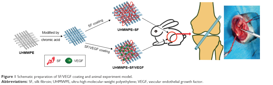 | Figure 1 Schematic preparation of SF/VEGF coating and animal experiment model. |
Characterizations
The morphology of samples in three groups was evaluated by field emission scanning electron microscopy (FESEM; S-4800; Hitachi Ltd., Tokyo, Japan) at an accelerating voltage of 10 kV after gold spouting.
Attenuated total reflectance (ATR) on a Fourier transform infrared (FTIR) Nicolet 6700 spectrophotometer was performed in the range of 1,000 to 4,000/cm with spectral resolution of 4/cm to assess the structure of SF and SF/VEGF. Furthermore, samples of three groups were immersed in deionized water for 24 h and, then, evaluated by ATR-FTIR against to investigate the solubility of SF coating.
Surface wettability of samples was evaluated by water contact angle (JC200C1; Zhongchen Co., Shanghai, China). Images of droplets were recorded through image analyzer to measure the contact angles.
Samples with a length of 10 cm and a diameter of 0.6 mm were applied to measure the tensile strength by an electronic universal testing machine (CXT-4104; MTS Systems Corporation, Eden Prairie, MN, USA). The strain rate and gage length in the measurements were 10 mm/min and 40 mm, respectively.
VEGF release study
The UHMWPE samples (n=6) coated with VEGF/SF was immersed in 1 mL of 1 M Dulbecco’s Phosphate Buffered Saline (pH =7.4) and incubated on a shaking bath (125 rpm) at 37°C. A total of 1 mL of supernatant was collected and replaced with an equal volume of fresh phosphate buffered saline at each selected time point. The total collected supernatant of 6 mL at each time point was centrifuged for 2 min (100,000× g, 4°C) and then freeze-dried to a volume of 60 μL. The release of VEGF was quantified using ELISA kit (Abcam, Cambridge, UK) according to the manufacturer’s instructions.
Cytocompatibility tests
BMSCs were isolated from New Zealand White rabbits with an average weight of 2.5 kg and cultured in Dulbecco’s Modified Eagle’s Medium (Thermo Fisher Scientific, Waltham, MA, USA) at 37°C with 5% CO2 in the incubator. BMSCs on passage 3 used for the experiments were diluted to a cell density of 1×10⁵/mL. A total of 500 μL cells’ suspension was dispensed into each well with one sample sheet at the bottom. After 24 h of cell culture, the sheets were transferred into another 24-well plate, followed by adding 500 μL of complete medium in each well.
After culture for 3, 7, and 14 days, the samples were fixed by 2.5% glutaraldehyde for 2 h and followed by dehydration with graded ethanol. FESEM was used to observe the morphology of cells. The samples were sputtered with gold for 120 s at a current of 10 mA.
Cell counting was performed using cell counting kit-8 (CCK-8) assay at different time points (3, 7, and 14 days) (n=3). A total of 50 μL of CCK-8 solution (Dojindo, Tokyo, Japan) was added into each well and reacted for 4 h in the incubator. A total of 100 μL of supernatant was transferred to a 96-well plate, and the absorbance was measured at 450 nm with a microplate reader (Multiskan FC, Waltham, MA, USA). The standard curve was established according to the data of calibration materials of the kit to calculate the corresponding cell number of each specimen.
Animal experiments
All the animal experiment protocols were approved by the Animal Research Committee of Shanghai Jiaotong University Animal Science Department. All procedures were performed following the Guide for the Care and Use of Laboratory Animals of the National Institutes of Health and the Animal Welfare Act. A total of 36 male New Zealand White rabbits (2.8–3.2 kg) were performed ACL reconstruction surgery (Figure 1). The animals were generally anesthetized with intramuscular injection of 0.8 mL of xylazine hydrochloride and 0.8 mL of diazepam. The left hind limb was shaved and prepped with betadine. The operative areas were draped, and sterile technique was ensured throughout the procedure. First, a 3–4 cm medial arthrotomy was made to expose and excise the ACL. Second, 2 mm diameter bone tunnels were drilled at the femoral and tibial anatomical insertions of the native ACL using a Kirschner wire. Third, the braided grafts were placed through the tunnels and knotted at both ends out of the femoral and tibial bone tunnel. After the graft was fixed firmly, the wound was irrigated with sterile saline solution. Finally, capsular layers and skins were closed using 3–0 sutures. The animals were returned to cages without immobility. The penicillin was injected into these animals intramuscularly with 100,000 U/kg for consecutive 3 days after surgery. Three rabbits in each group were sacrificed 6 weeks postoperatively, and the femur–graft–tibia complex (FGTC) samples were collected for histological evaluation. Then, eight rabbits of each group were sacrificed 12 weeks postoperatively, and FGTC samples were collected for microcomputed tomography (micro-CT) scan, histological evaluation, and biomechanical test. In addition, three rabbits undergone the same operation procedure with no grafts were sacrificed 1 day after surgery to collect specimens to perform micro-CT scan.
Histological examinations
The FGTC specimens were fixed in 10% formalin, decalcified, and embedded in paraffin after micro-CT scan. Five micron thick sections were cut perpendicularly to the longitudinal axis of the bone tunnel. The sections were stained with the hematoxylin and eosin stain, the Masson trichrome stain, and the PicroSirius red stain to distinguish fibrous and bony tissue. Polarized light microscopy (Olympus DM2500P; Leica Microsystems, Wetzlar, Germany) was used to visualize the sections. Digital images were captured to evaluate the histomorphology.
Micro-CT analysis
The bone tunnel areas and bone mass in peri-implant tissue were assessed with Skyscan 1176 micro-CT imaging system (BrukerOptik GmbH, Ettlingen, Belgium). Specimens were scanned perpendicularly to the long bone axis at a spatial resolution of 18 μm (1 mm aluminum filter, 65 kV, 378 μA). NRecon, DataViewer, and CTVox were used to analyze the data. The cross-sectional areas of the bone tunnels at which the depth was 5 mm from the femur joint surface and tibial joint surface were selected. ImageJ software was applied to measure the bone tunnel areas. A cylinder-shaped region of interest (4 mm in diameter and 4 mm in height) around the bone tunnel was chosen, and the reconstructed 3D datasets were analyzed to obtain the trabecular bone volume fraction of the total tissue volume of interest (BV/TV) value. Three rabbits sacrificed 1 day after surgery were used to obtain the base values of bone tunnel area and BV/TV.
Biomechanical testing
The FGTC specimens (n=3 in each group) were harvested and carefully dissected to remove the surrounding soft tissue until only the ACL graft connecting the femur and tibia. Two specifically designed clamps were used to fix the femur and the tibia in order to ensure the two bones maintaining perpendicular in the testing machine (AGS-X; Shimadzu, Co., Kyoto, Japan). A preload of 1 N followed by a load displacement rate of 2 mm/min were applied to the samples until failure, which was defined that the graft was pulled out or ruptured. The load to failure was recorded to estimate the graft–bone healing.
Statistical analysis
Data were reported as mean ± standard deviation. Analysis of variance and Tukey’s test for multiple comparisons were used to determine the groups with significant difference. All analyses were performed using GraphPad Prism v.6.01 and p<0.05 was considered to be significant.
Results
Characterizations
The surface morphologies of UHMWPE fibers before and after immersion in SF solution were observed by FESEM. As shown in Figure 2A and B, the surfaces of UHMWPE fiber were smooth. After the introduction of SF, increased surface roughness and bridging SF coating among fibers were observed in both UHMWPE–SF/VEGF group and UHMWPE–SF group (Figure 2C–F).
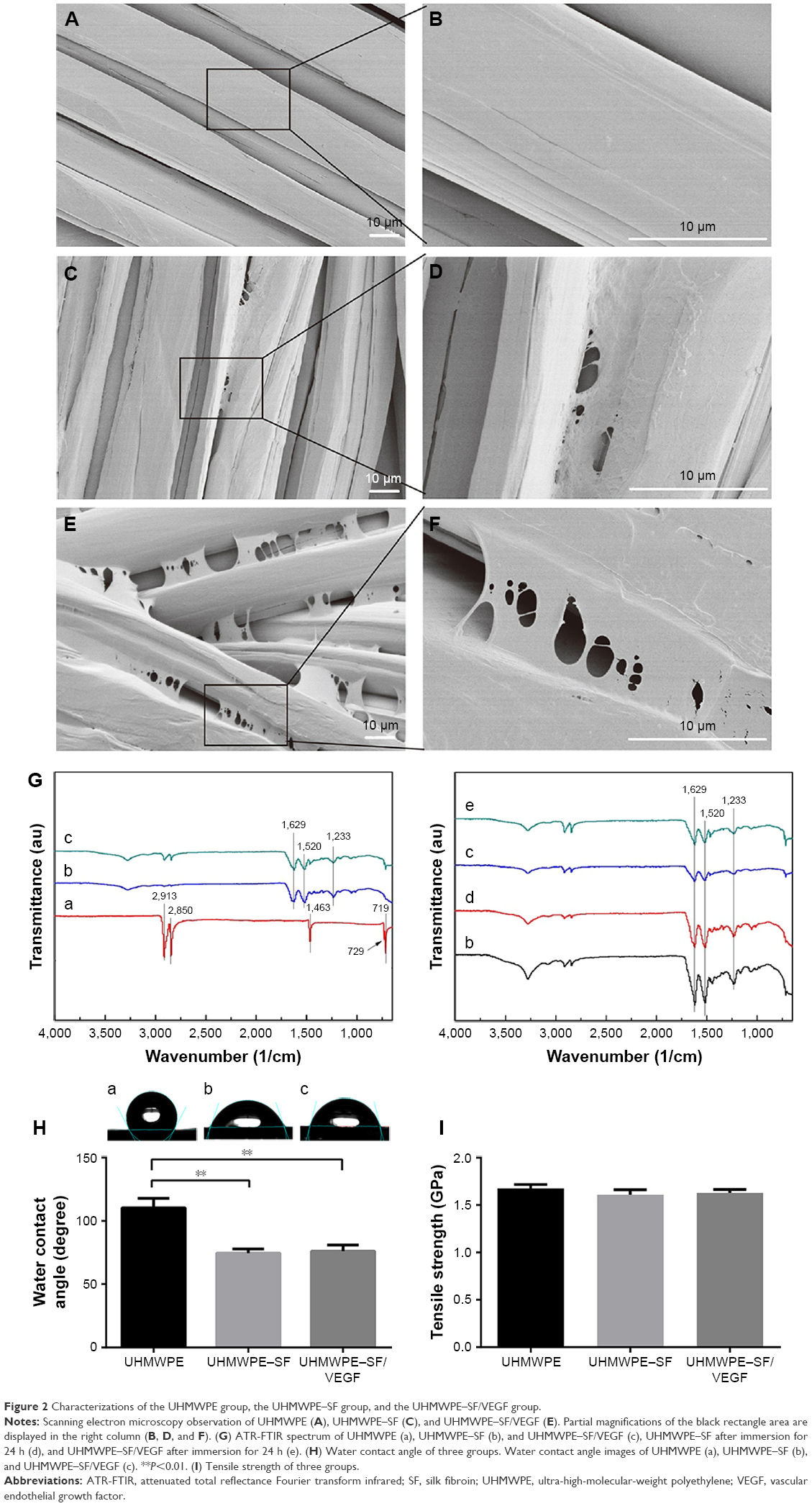 | Figure 2 Characterizations of the UHMWPE group, the UHMWPE–SF group, and the UHMWPE–SF/VEGF group. |
The secondary structures of the coating were analyzed by FTIR (Figure 2G). The characteristic peaks of UHMWPE at 719, 729, 1,463, 2,850, and 2,913/cm were ascribed to the vibrations of CH2 in the UHMWPE chain.26 After samples were immersed in SF solution and tested, the typical peaks of SF at 1,629/cm (for amide I) and 1,520/cm (for amide II) exhibited, which proved that there was some β-sheet formation of SF.25 This result verified that the UHMWPE fibers were coated by SF and in agreement with the FESEM results. There were no new characteristic peaks observed after the introduction of VEGF because the spectrum of SF was similar to the spectrum of SF. The SF coating samples were placed in water for 24 h to observe the solubility of SF. The characteristic peak intensity was not weakened significantly after 24 h water immersion (Figure 2G-d and G-e), demonstrating the stability of SF coating.
The surface hydrophilia of the UHMWPE group was analyzed by water contact angle measurement (Figure 2H). The contact angle of the UHMWPE–SF group (74.50°±3.27°) and the UHMWPE–SF/VEGF group (76.07°±4.87°) was significantly smaller than the pristine UHMWPE (110.40°±7.46°), demonstrating that the surface hydrophilia of the UHMWPE group was increased after coating with SF and SF/VEGF.
The tensile strengths of the UHMWPE group, the UHMWPE–SF group, and the UHMWPE–SF/VEGF group were 1.676±0.041, 1.609±0.053, and 1.488±0.062 GPa, respectively. There was no significant difference among the three groups (Figure 2I). The slight decrease in tensile strength after coating with SF and SF/VEGF may be attributed to the chain scission of macromolecules during the chromic acid modification process.
According to the ELISA results (Figure 3A), the cumulative release profile of VEGF-loaded SF coating exhibited a sustained release of VEGF for up to 28 days with an initial burst release.
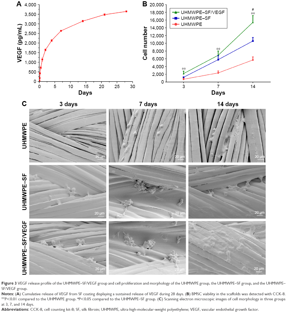 | Figure 3 VEGF release profile of the UHMWPE–SF/VEGF group and cell proliferation and morphology of the UHMWPE group, the UHMWPE–SF group, and the UHMWPE–SF/VEGF group. |
In vitro cytocompatibility
Statistical analysis of CCK-8 results (Figure 3B) indicated that when cultured for 3 and 7 days, cell proliferation levels in the UHMWPE–SF/VEGF group and the UHMWPE–SF group were higher than that in the UHMWPE group. After 14-day cultivation, the difference between the UHMWPE–SF/VEGF group and the UHMWPE–SF group was significant. Moreover, cell morphology of the samples of three groups was observed by FESEM after culture for 3, 7, and 14 days (Figure 3C). Few BMSCs were distributed on the pristine UHMWPE, and most of cells were oval-shaped until be cultured for 7 days. Filopodia of BMSCs adhered on the surface of UHMWPE could not be observed until 14-day cultivation. In the UHMWPE–SF group and the UHMWPE–SF/VEGF group, it was observed that BMSCs clustered on the surface after 7-day culture. BMSCs adhered extensively on the surface of UHMWPE–SF/VEGF after 14-day culture. Overall, BMSCs in the UHMWPE–SF/VEGF group showed a better proliferation and adhesion.
In vivo histological evaluation
Animal testing was performed to observe the effect of SF/VEGF coating on angiogenesis of peri-implant tissue and histocompatibility of UHMWPE. Histological evaluation based on the histomorphology of hematoxylin-eosin staining and collagen structure of Masson trichrome staining was performed to assess graft–bone integration at 6 and 12 weeks after surgery. The graft–bone interface tissue was mainly constitutive of cellular and vascular fibrous tissue. In the UHMWPE group, the graft was circled by scattered collagen tissue and a great number of collagen formed adhering to the bone side. There was an obvious gap between collagen-circled graft and collagen-adhering bone 6 weeks postoperatively (Figure 4A and B). At the time of 12 weeks after surgery, abundant cells with round or oval nucleus stacked along the border of host bone and the broad interface between graft and bone were filled with disorderly collagen tissue (Figure 4C and D). In the UHMWPE–SF group, the collagen uniformly distributed along the bone penetrating into the graft fibers 6 weeks after surgery (Figure 4E and F). The well-organized collagen aggregated more broadly at the interface at the time of 12 weeks after surgery (Figure 4G and H). In the UHMWPE–SF/VEGF group, well-organized collagen tissue attached to the bone side and plentiful blood vessels were observed postoperatively at the time of 6 weeks (Figure 4I and J). At the time of 12 weeks after surgery, the graft and bone fit closely with dense and uniformly oriented collagen and blood vessel grew into the graft (Figure 4K and L). Newly formed vessels at the interface were obviously observed in the UHMWPE–SF/VEGF group. The histological evaluation results proved that SF/VEGF coating promoted the angiogenesis of peri-implant tissue and enhanced the orderly arrangement of newly formed collagen.
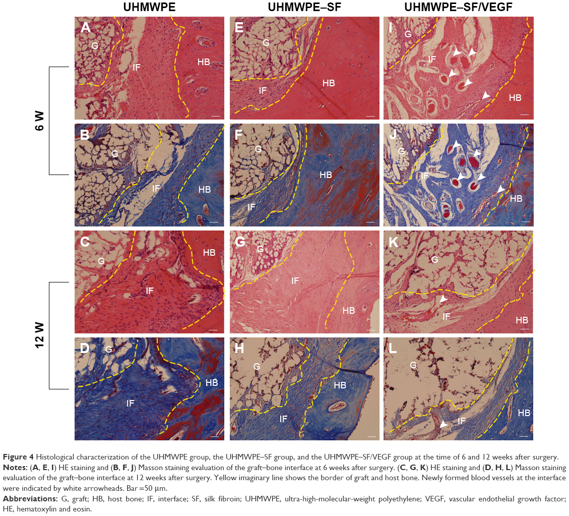 | Figure 4 Histological characterization of the UHMWPE group, the UHMWPE–SF group, and the UHMWPE–SF/VEGF group at the time of 6 and 12 weeks after surgery. |
Furthermore, the PicroSirius red staining was performed to analyze the collagen types at the time of 12 weeks after surgery. As shown in Figure 5, sections were observed under normal and polarizing condition. In the UHMWPE group, disordered collagen tissue was observed at the interface. In the UHMWPE–SF group, collagen fibers at the interface oriented themselves parallel to the implant surface. In the UHMWPE–SF/VEGF group, collagen fibers connecting the host bone directly were observed. The collagen connecting the host bone at the interface was mainly composed of collagen III in the UHMWPE group and the UHMWPE–SF group. In the UHMWPE–SF/VEGF group, collagen I bridged graft and bone and penetrated into the graft fibers at the interface. The arrangement of collagen was more ordered in the UHMWPE–SF group and the UHMWPE–SF/VEGF group than that in the UHMWPE group, which was consistent with above Masson staining results.
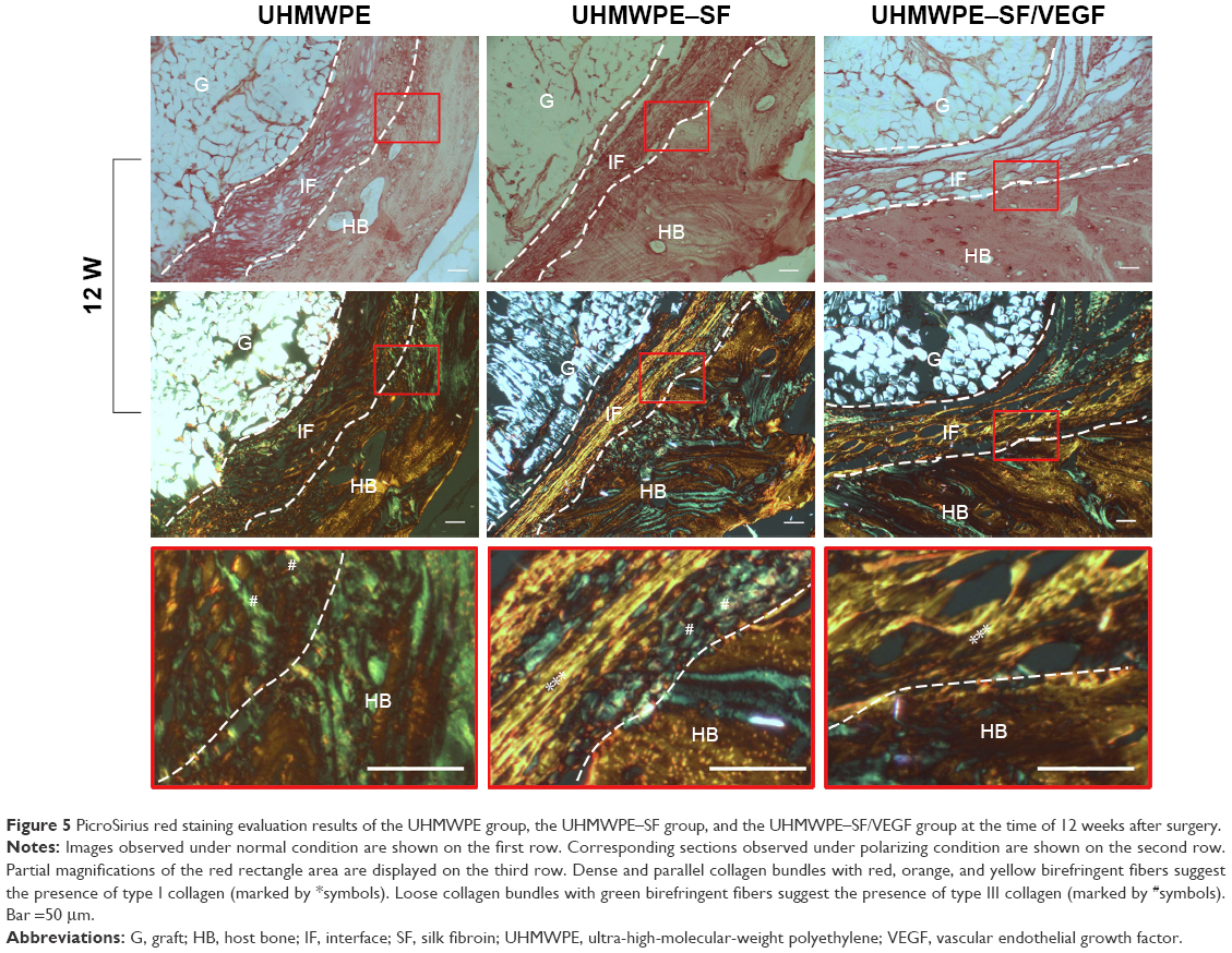 | Figure 5 PicroSirius red staining evaluation results of the UHMWPE group, the UHMWPE–SF group, and the UHMWPE–SF/VEGF group at the time of 12 weeks after surgery. |
Micro-CT analysis
The peri-implant bone tissues were analyzed by measuring the bone tunnel areas and BV/TV values at the time of 12 weeks postoperatively (Figure 6). The base value of bone tunnel area measured at the time of 1 day after surgery was 12.53±0.07 mm2. The bone tunnel areas of the UHMWPE group, the UHMWPE–SF group, and the UHMWPE–SF/VEGF group were 16.39±0.74, 14.67±0.36, and 12.87±0.71 mm2, respectively. As shown in Figure 6B, the areas of bone tunnels were enlarged in the UHMWPE and UHMWPE–SF groups at the time of 12 weeks after surgery. The bone tunnel area of the UHMWPE–SF/VEGF group was significantly smaller than that of the other two groups. The base value of BV/TV measured at the time of 1 day after surgery was 19.86%±0.43%. The BV/TV values of the UHMWPE group, the UHMWPE–SF group, and the UHMWPE–SF/VEGF group were 9.35%±2.25%, 13.16%±2.16%, and 17.08%±1.81%, respectively. As shown in Figure 6C, compared to the base value, the BV/TV value in the UHMWPE and UHMWPE–SF groups decreased. The area of BV/TV in the UHMWPE–SF/VEGF group was higher than that in the other two groups.
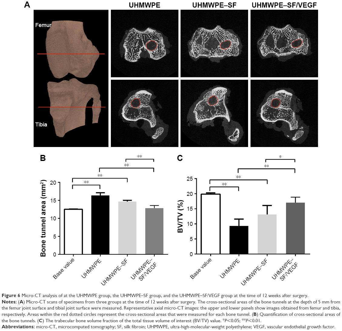 | Figure 6 Micro-CT analysis of at the UHMWPE group, the UHMWPE–SF group, and the UHMWPE–SF/VEGF group at the time of 12 weeks after surgery. |
Mechanical testing
The maximum pull-out load and stiffness of the implanted ACL grafts were analyzed to assess the anchoring strength between graft and host bone at the time of 12 weeks postoperatively (Figure 7). All specimens failed when the grafts were pulled out from the bone tunnel. No failures occurred as a result of graft rupture. Failure loaded in the UHMWPE–SF/VEGF group (93.34±4.31 N) was significantly higher than that in the other two groups. Failure loaded in the UHMWPE group (43.08±7.80 N) was significantly lower compared to the other groups. The difference of failure load between the UHMWPE group (43.08±7.80 N) and the UHMWPE–SF group (72.54±7.21N) was significant. Similarly, the stiffness in the UHMWPE–SF/VEGF group (45.63±3.93 N/mm) was significantly higher than that in the other two groups. The difference of stiffness between the UHMWPE group (21.67±1.52 N/mm) and the UHMWPE–SF group (35.93±3.16 N/mm) was significant.
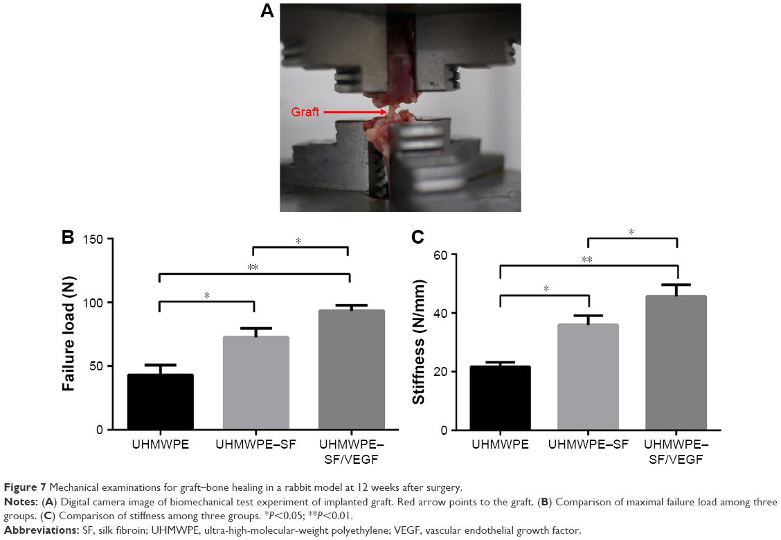 | Figure 7 Mechanical examinations for graft–bone healing in a rabbit model at 12 weeks after surgery. |
Discussion
The chemical inertness and poor interfacial adhesion of UHMWPE were not conducive to cellular adhesion and proliferation. The quality of graft–bone reaction depends on implant, surface topography, and biological activity.27,28 Surface modification is commonly used to enhance graft–bone integration, such as plasma treatment,29,30 acid etching,31 and chemical grafting.32,33 Besides, the delivery method of localized drugs or growth factors is found to be an efficient method to overcome graft associated problems including healing deficits and bacterial infection.34,35 In the present study, the surface modification technique was used to coat the biological active factor on the surface of UHMWPE fibers. Chromic acid treatment was applied to introduce functional groups to the surface of fibers and etch the amorphous regions of fibers. Then, SF loading growth factor VEGF was coated on the modified surface of UHMWPE to achieve a sustained release effect. A total of 200 ng/mL of VEGF/SF has been proved to improve neovascularization in rabbit model,36 so solution of 200 ng/mL of VEGF/SF was made to accomplish dip coating in this study. With our modified method, the UHMWPE fibers were endowed with biological activity using SF as the medium. Meanwhile, the surface hydrophilia of UHMWPE fibers was increased after SF/VEGF coating. An ideal modification method contributes to acquire desired properties without damaging other favorable characters. Manoj Kumar et al37 engineered a thin porous surface layer on UHMWPE substrate by etching and lyophilizing technique and impregnated gentamicin loaded chitosan to achieve an antibacterial effect. However, the hardness and elastic modulus decreases were concomitant due to the chitosan filled in the pores and the presence of partially unfilled pores on the surface. The tensile strength testing results in this study proved that the modification could be achieved without compromising the mechanical behavior of UHMWPE fibers.
Surface modifications change the hydrophilicity, morphology, energy, microstructure, and roughness of material, resulting in an impact on cytocompatibility. Considering that first cells migrating at the graft surface are multipotent mesenchymal cells,38 BMSCs could be adopted to investigate the cytocompatibility of UHMWPE in this study. According to the FESEM observation and CCK-8 results, BMSCs exhibited a better proliferation and adhesion performance after SF/VEGF was coated on the surface of UHMWPE. SF coating improves the surface roughness of UHMWPE, and it is evident that rough surface enhances the process of cell attachment with rich filopodia extension.39,40 The increased surface roughness even outweighs the enhanced wettability for the adhesion and proliferation of fibroblast cells.18 Besides, as a versatile biomaterial in tissue engineering, SF is capable of supporting the proliferation and differentiation of BMSCs along the osteogenic lineage.41 The proliferation level of BMSCs in the UHMWPE–SF/VEGF group was significantly higher than that of the UHMWPE–SF group after 14-day cultivation, because the sustained VEGF release was conductive to BMSC proliferation and adhesion. Zhang et al42 demonstrated that VEGF stimulated the proliferation and osteogenic differentiation of BMSC by promoting the expression of heme oxygenase-1. Besides, VEGF regulated BMSC fate by increasing osteoblast differentiation and reducing adipocyte differentiation.43 Therefore, sustained release of VEGF from the SF coating can contribute to solve the problem of peri-implant osteolysis.
There are two types of connection at native interface between ACL ligament and bone:44 direct insertion and indirect insertion. The former is composed of the following four zones: tendon, unmineralized fibrocartilage, mineralized fibrocartilage, and bone. The latter contains collagen fibers called Sharpey’s fibers blending with periosteal collagen, thus anchoring to underlying bone. According to the result of using a calcium phosphate apatite/polydopamine hybridized-polyethylene terephthalate graftin ACL reconstruction rabbit model, fibrocartilage transitional zones were observed at the time of 12 weeks after surgery.45 According to the result of using soft tissue autografts in ACL reconstruction rabbit model, Sharpey-like oblique collagen bound to the bone was observed at the time of 2 weeks after surgery.46 Fibrocartilage transitional zones were not observed in our study due to the lack of osteoinduction and osteoconduction of UHMWPE. At 12 weeks postoperatively, Sharpey-like fibers connecting to the host bone were observed in the UHMWPE–SF/VEGF group, which formed much later than the autografts. As soon as the graft was implanted in vivo, a layer of water molecule would form around the graft, facilitating extracellular matrix proteins to adsorb on the implant surface.47 The proteins then regulated cellular adhesion, migration, and differentiation initially. It is difficult for cells to colonize on the surface of the pristine UHMWPE due to its poor hydrophilicity. Consequently, BMSCs’ aggregation was hindered in the initial stage after surgery. In this study, it was observed that the integration between UHMWPE grafts and host bone relied on a layer of fibrous tissue. VEGF helped to induce cells to form capillary-like tubules to increase the vascularity of implant site, which might help the Sharpey-like fibers to anchor to the bone in the UHMWPE–SF/VEGF group. It was noted that there was no new bone formation in this study. Similarly, Zhang et al42 found that the single VEGF from the silk gel or silk scaffold only promoted angiogenesis and more tissue infiltration into the gel or scaffold, in which no bone regeneration was observed, while combining VEGF and BMP-2 released from the silk gel or silk scaffold could promote angiogenesis and new bone formation.48,49 Besides, graft motion in the bone tunnel could be inevitable in ACL reconstruction model, which impeded bone regeneration. It was verified that interfacial implant movement will lead to soft tissue formation instead of bone.50
As a structure tie, a synthetic device for ACL reconstruction is required to undertake constantly tensile load. Such implants can fail due to implant motion, inflammation, bone resorption, and osteolysis.51 According to our micro-CT analysis, the bone resorption and osteolysis around UHMWPE grafts were ameliorated by SF/VEGF coating. In contrast to the high tensile strength of collagen I fibers, collagen III is less orderly and thinner.52 Therefore, in the UHMWPE–SF/VEGF group, the connecting between graft and bone was the firmest and the failure load and stiffness were the highest. This might decrease the frequency and magnitude of motion of the graft inside the bone tunnel. A total of 150 μm of oscillating motion of metal implants hindered the bone in growth when scaffolds were implanted in dog distal femurs.53 Although the exact permissible motion value for UHMWPE is still unknown, it was suggested that the orderly anchoring collagen I fibers binded graft strongly to bones such that there was minimal movement between the implant and host tissue. In contrast, although there was no new bone formation, VEGF promoted the angiogenesis so that the vascular networks support the metabolic demands of repair and the influx of cells providing osteogenic cues,54 which is adverse to the activity of osteoclasts.55
The graft choice for ACL reconstruction is the focus of attention in sports medicine.56 Prosthetic ligaments could not only avoid the disadvantages of autografts and allografts such as donor site injury, immunological reaction, and disease transmission, but also allow early rehabilitation with more rapid return to a preinjury level of activity.57 In our study, VEGF loaded by SF coating onto the surface of UHMWPE enhanced the biological performance of UHMWPE fibers, which revealed the potential application inartificial ligaments. UHMWPE-braided graft had been used as an ACL reconstructive option,58 but researches about its clinical outcomes were rarely reported due to the withdraw of artificial ligaments from the market after a short-time availability. The ultimate failure load for native young specimens of the femur–ACL–tibia complex was 2,160±157 N.59 At present, artificial ligaments available are mainly made of polyester.57 Compared to polyester, the high performance of UHMWPE in mechanical behavior makes it possible for prosthetic ligament to meet the mechanical requirement of ACL with a smaller cross-sectional area. Thereupon, the size of the bone tunnel needed drilling during ACL reconstruction operation could be smaller, which is a favorable factor for bone regeneration.60 This could be another advantage for UHMWPE application in artificial ligament needed to be investigated further.
Conclusion
In this study, a novel strategy was used to modify UHMWPE with biological activity. The incorporation of VEGF onto the surface of UHMWPE ensured through the medium SF and sustained release effect of VEGF was accomplished up to 28 days. VEGF loaded by SF coating onto the surface of UHMWPE increased the angiogenesis at the interface and enhanced the anchoring strength between graft and bone and, thus, ameliorated the bone resorption and osteolysis of peri-implant bone tissue. It is suggested that SF/VEGF coating is of great potential for the application of UHMWPE to ACL reconstruction.
Acknowledgments
This study was supported by National 863 Hi-tech Project (2015AA033703), National Natural Science Foundation of China (No 81370052 and No 81572108), and National Key R&D Program of China (2016YFC1100300).
Disclosure
The authors report no conflicts of interest in this work.
References
Chen EH, Black J. Materials design analysis of the prosthetic anterior cruciate ligament. J Biomed Mater Res. 1980;14(5):567–586. | ||
Dumbleton JH, D’Antonio JA, Manley MT, Capello WN, Wang A. The basis for a second-generation highly cross-linked UHMWPE. Clin Orthop Relat Res. 2006;453:265–271. | ||
Lin SP, Han JL, Yeh JT, Chang FC, Hsieh KH. Composites of UHMWPE fiber reinforced PU/epoxy grafted interpenetrating polymer networks. Eur Polymer J. 2007;43(3):996–1008. | ||
Kandahari AM, Yang X, Laroche KA, Dighe AS, Pan D, Cui Q. A review of UHMWPE wear-induced osteolysis: the role for early detection of the immune response. Bone Res. 2016;4:16014. | ||
Riveiro A, Soto R, del Val J, et al. Laser surface modification of ultra-high-molecular-weight polyethylene (UHMWPE) for biomedical applications. Appl Surf Sci. 2014;302:236–242. | ||
An M, Xu H, Lv Y, et al. Ultra-strong gel-spun ultra-high molecular weight polyethylene fibers filled with chitin nanocrystals. RSC Adv. 2016;6(25):20629–20636. | ||
Yeh J-T, Lin S-C, Tu C-W, Hsie K-H, Chang F-C. Investigation of the drawing mechanism of UHMWPE fibers. J Sci Mater. 2008;43(14):4892–4900. | ||
Holloway JL, Lowman AM, VanLandingham MR, Palmese GR. Interfacial optimization of fiber-reinforced hydrogel composites for soft fibrous tissue applications. Acta Biomater. 2014;10(8):3581–3589. | ||
Ren Y, Ding Z, Wang C, Zang C, Zhang Y, Xu L. Influence of DBD plasma pretreatment on the deposition of chitosan onto UHMWPE fiber surfaces for improvement of adhesion and dyeing properties. Appl Surf Sci. 2017;396:1571–1579. | ||
Reis J, Kanagaraj S, Fonseca A, et al. In vitro studies of multiwalled carbon nanotube/ultrahigh molecular weight polyethylene nanocomposites with osteoblast-like MG63 cells. Braz J Med Biol Res [Revista brasileira de pesquisas medicas e biologicas]. 2010;43(5):476–482. | ||
Chukov DI, Stepashkin AA, Maksimkin AV, et al. Investigation of structure, mechanical and tribological properties of short carbon fiber reinforced UHMWPE-matrix composites. Composites B Eng. 2015;76:79–88. | ||
Holloway JL, Lowman AM, Palmese GR. Mechanical evaluation of poly(vinyl alcohol)-based fibrous composites as biomaterials for meniscal tissue replacement. Acta Biomater. 2010;6(12):4716–4724. | ||
Sa R, Wei Z, Yan Y, et al. Catechol and epoxy functionalized ultrahigh molecular weight polyethylene (UHMWPE) fibers with improved surface activity and interfacial adhesion. Compos Sci Technol. 2015;113:54–62. | ||
Holloway JL, Lowman AM, VanLandingham MR, Palmese GR. Chemical grafting for improved interfacial shear strength in UHMWPE/PVA-hydrogel fiber-based composites used as soft fibrous tissue replacements. Compos Sci Technol. 2013;85:118–125. | ||
Li Z, Zhang W, Wang X, Mai Y, Zhang Y. Surface modification of ultra high molecular weight polyethylene fibers via the sequential photoinduced graft polymerization. Appl Surf Sci. 2011;257(17):7600–7608. | ||
Firouzi D, Youssef A, Amer M, et al. A new technique to improve the mechanical and biological performance of ultra high molecular weight polyethylene using a nylon coating. J Mech Behav Biomed Mater. 2014;32:198–209. | ||
Silva MA, Gomes PS, Vila M, et al. New titanium and titanium/hydroxyapatite coatings on ultra-high-molecular-weight polyethylene-in vitro osteoblastic performance. Biomed Mater. 2010;5(3):35014. | ||
Novotna Z, Rimpelova S, Jurik P, et al. The interplay of plasma treatment and gold coating and ultra-high molecular weight polyethylene: on the cytocompatibility. Mater Sci Eng C Mater Biol Appl. 2017;71:125–131. | ||
Saran U, Gemini Piperni S, Chatterjee S. Role of angiogenesis in bone repair. Arch Biochem Biophys. 2014;561:109–117. | ||
Street J, Bao M, deGuzman L, et al. Vascular endothelial growth factor stimulates bone repair by promoting angiogenesis and bone turnover. Proc Natl Acad Sci U S A. 2002;99(15):9656–9661. | ||
Studer D, Millan C, Öztürk E, Maniura-Weber K, Zenobi-Wong M. Molecular and biophysical mechanisms regulating hypertrophic differentiation in chondrocytes and mesenchymal stem cells. Eur Cell Mater. 2012;24:118–135. | ||
Chan Charles KF, Seo Eun Y, Chen James Y, et al. Identification and specification of the mouse skeletal stem cell. Cell. 2015;160(1–2):285–298. | ||
Kundu B, Rajkhowa R, Kundu SC, Wang X. Silk fibroin biomaterials for tissue regenerations. Adv Drug Deliv Rev. 2013;65(4):457–470. | ||
Tong S, Xu DP, Liu ZM, Du Y, Wang XK. Synthesis of the new-type vascular endothelial growth factor-silk fibroin-chitosan three-dimensional scaffolds for bone tissue engineering and in vitro evaluation. J Craniofac Surg. 2016;27(2):509–515. | ||
Jiang J, Wan F, Yang J, et al. Enhancement of osseointegration of polyethylene terephthalate artificial ligament by coating of silk fibroin and depositing of hydroxyapatite. Int J Nanomedicine. 2014;9:4569–4580. | ||
Gao Q, Hu J, Li R, et al. Radiation synthesis of a new amidoximated UHMWPE fibrous adsorbent with high adsorption selectivity for uranium over vanadium in simulated seawater. Radiat Phys Chem. 2016;122:1–8. | ||
Mao LX, Liu JQ, Zhao JL, et al. Effect of micro-nano-hybrid structured hydroxyapatite bioceramics on osteogenic and cementogenic differentiation of human periodontal ligament stem cell via Wnt signaling pathway. Int J Nanomedicine. 2015;10:7031–7044. | ||
Lin KL, Xia LG, Gan JB, et al. Tailoring the nanostructured surfaces of hydroxyapatite bioceramics to promote protein adsorption, osteoblast growth, and osteogenic differentiation. ACS Appl Mater Interfaces. 2013;5(16):8008–8017. | ||
Preedy EC, Brousseau E, Evans SL, Perni S, Prokopovich P. Adhesive forces and surface properties of cold gas plasma treated UHMWPE. Colloids Surf A Physicochem Eng Asp. 2014;460:83–89. | ||
Aziz G, Cools P, De Geyter N, Declercq H, Cornelissen R, Morent R. Dielectric barrier discharge plasma treatment of ultrahigh molecular weight polyethylene in different discharge atmospheres at medium pressure: a cell-biomaterial interface study. Biointerphases. 2015;10(2):029502. | ||
Li W, Meng L, Wang L, Mu J, Pan Q. Surface modification of ultra-high molecular weight polyethylene fibers by chromic acid. Surf Interface Anal. 2016;48(12):1316–1319. | ||
Hu J, Feng X, Liu Z, Zhao Y, Chen L. Surface amine-functionalization of UHMWPE fiber by bio-inspired polydopamine and grafted hexamethylene diamine. Surf Interface Anal. 2017;49(7):640–646. | ||
Wang N, Trunfio-Sfarghiu AM, Portinha D, et al. Nanomechanical and tribological characterization of the MPC phospholipid polymer photografted onto rough polyethylene implants. Colloids Surf B Biointerfaces. 2013;108:285–294. | ||
Simmons CA, Alsberg E, Hsiong S, Kim WJ, Mooney DJ. Dual growth factor delivery and controlled scaffold degradation enhance in vivo bone formation by transplanted bone marrow stromal cells. Bone. 2004;35(2):562–569. | ||
Pichavant L, Amador G, Jacqueline C, Brouillaud B, Heroguez V, Durrieu MC. pH-controlled delivery of gentamicin sulfate from orthopedic devices preventing nosocomial infections. J Control Release. 2012;162(2):373–381. | ||
Farokhi M, Mottaghitalab F, Ai J, Shokrgozar MA. Sustained release of platelet-derived growth factor and vascular endothelial growth factor from silk/calcium phosphate/PLGA based nanocomposite scaffold. Int J Pharm. 2013;454(1):216–225. | ||
Manoj Kumar R, Gupta P, Sharma SK, et al. Sustained drug release from surface modified UHMWPE for acetabular cup lining in total hip implant. Mater Sci Eng C Mater Biol Appl. 2017;77:649–661. | ||
Schwartz Z, Martin JY, Dean DD, Simpson J, Cochran DL, Boyan BD. Effect of titanium surface roughness on chondrocyte proliferation, matrix production, and differentiation depends on the state of cell maturation. J Biomed Mater Res. 1996;30(2):145–155. | ||
Gittens RA, McLachlan T, Olivares-Navarrete R, et al. The effects of combined micron-/submicron-scale surface roughness and nanoscale features on cell proliferation and differentiation. Biomaterials. 2011;32(13):3395–3403. | ||
Chug A, Shukla S, Mahesh L, Jadwani S. Osseointegration – molecular events at the bone–implant interface: a review. J Oral Maxillofac Surg Med Pathol. 2013;25(1):1–4. | ||
Melke J, Midha S, Ghosh S, Ito K, Hofmann S. Silk fibroin as biomaterial for bone tissue engineering. Acta Biomater. 2016;31:1–16. | ||
Zhang LF, Qi J, Zuo GL, et al. Osteoblast-secreted factors promote proliferation and osteogenic differentiation of bone marrow stromal cells via VEGF/heme-oxygenase-1 pathway. PLoS One. 2014;9(6):e99946. | ||
Berendsen AD, Olsen BR. Regulation of adipogenesis and osteogenesis in mesenchymal stem cells by vascular endothelial growth factor A. J Intern Med. 2015;277(6):674–680. | ||
Shen H, Qiao G, Cao H, Jiang Y. An histological study of the influence of osteoinductive calcium phosphate ceramics on tendon healing pattern in a bone tunnel with suspensory fixation. Int Orthop. 2010;34(6):917–924. | ||
Li H, Chen S, Chen J, et al. Mussel-inspired artificial grafts for functional ligament reconstruction. ACS Appl Mater Interfaces. 2015;7(27):14708–14719. | ||
Kawakami Y, Takayama K, Matsumoto T, et al. Anterior cruciate ligament-derived stem cells transduced with BMP2 accelerate graft-bone integration after ACL reconstruction. Am J Sports Med. 2017;45(3):584–597. | ||
Singhatanadgit W. Biological responses to new advanced surface modifications of endosseous medical implants. Bone Tissue Regener Insights. 2012;2(2):1–11. | ||
Zhang W, Wang X, Wang S, et al. The use of injectable sonication-induced silk hydrogel for VEGF(165) and BMP-2 delivery for elevation of the maxillary sinus floor. Biomaterials. 2011;32(35):9415–9424. | ||
Zhang W, Zhu C, Wu Y, et al. VEGF and BMP-2 promote bone regeneration by facilitating bone marrow stem cell homing and differentiation. Eur Cell Mater. 2014;27(12):1. | ||
Albrektsson T, Johansson C. Osteoinduction, osteoconduction and osseointegration. Eur Spine J. 2001;10(2):S96–S101. | ||
Agarwal R, Garcia AJ. Biomaterial strategies for engineering implants for enhanced osseointegration and bone repair. Adv Drug Deliv Rev. 2015;94:53–62. | ||
Aaron JE. Periosteal Sharpey’s fibers: a novel bone matrix regulatory system? Front Endocrinol. 2012;3:98. | ||
Bragdon CR, Burke D, Lowenstein JD, et al. Differences in stiffness of the interface between a cementless porous implant and cancellous bone in vivo in dogs due to varying amounts of implant motion. J Arthroplasty. 1996;11(8):945–951. | ||
Tomlinson RE, Silva MJ. Skeletal blood flow in bone repair and maintenance. Bone Res. 2013;1(4):311–322. | ||
Trindade R, Albrektsson T, Tengvall P, Wennerberg A. Foreign body reaction to biomaterials: on mechanisms for buildup and breakdown of osseointegration. Clin Implant Dent Relat Res. 2016;18(1):192. | ||
Tejwani SG, Chen J, Funahashi TT, Love R, Maletis GB. Revision risk after allograft anterior cruciate ligament reconstruction: association with graft processing techniques, patient characteristics, and graft type. Am J Sports Med. 2015;43(11):2696–2705. | ||
Batty LM, Norsworthy CJ, Lash NJ, Wasiak J, Richmond AK, Feller JA. Synthetic devices for reconstructive surgery of the cruciate ligaments: a systematic review. Arthroscopy. 2015;31(5):957–968. | ||
Guidoin MF, Marois Y, Bejui J, Poddevin N, King MW, Guidoin R. Analysis of retrieved polymer fiber based replacements for the ACL. Biomaterials. 2000;21(23):2461–2474. | ||
Woo SLY, Hollis JM, Adams DJ, Lyon RM, Takai S. Tensile properties of the human femur-anterior cruciate ligament-tibia complex – the effects of specimen age and orientation. Am J Sports Med. 1991;19(3):217–225. | ||
Li Y, Chen SK, Li L, Qin L, Wang XL, Lai YX. Bone defect animal models for testing efficacy of bone substitute biomaterials. J Orthop Transl. 2015;3(3):95–104. |
 © 2017 The Author(s). This work is published and licensed by Dove Medical Press Limited. The full terms of this license are available at https://www.dovepress.com/terms.php and incorporate the Creative Commons Attribution - Non Commercial (unported, v3.0) License.
By accessing the work you hereby accept the Terms. Non-commercial uses of the work are permitted without any further permission from Dove Medical Press Limited, provided the work is properly attributed. For permission for commercial use of this work, please see paragraphs 4.2 and 5 of our Terms.
© 2017 The Author(s). This work is published and licensed by Dove Medical Press Limited. The full terms of this license are available at https://www.dovepress.com/terms.php and incorporate the Creative Commons Attribution - Non Commercial (unported, v3.0) License.
By accessing the work you hereby accept the Terms. Non-commercial uses of the work are permitted without any further permission from Dove Medical Press Limited, provided the work is properly attributed. For permission for commercial use of this work, please see paragraphs 4.2 and 5 of our Terms.