")
Back to Journals » International Journal of Nanomedicine » Volume 14
Rapid mineralization of hierarchical poly(l-lactic acid)/poly(ε-caprolactone) nanofibrous scaffolds by electrodeposition for bone regeneration
Authors Nie W, Gao Y, McCoul DJ, Gillispie GJ , Zhang Y , Liang L, He C
Received 16 February 2019
Accepted for publication 16 April 2019
Published 27 May 2019 Volume 2019:14 Pages 3929—3941
DOI https://doi.org/10.2147/IJN.S205194
Checked for plagiarism Yes
Review by Single anonymous peer review
Peer reviewer comments 4
Editor who approved publication: Prof. Dr. Anderson Oliveira Lobo
Wei Nie,1,2,* Yiming Gao,3,* David James McCoul,2 Gregory James Gillispie,2 YanZhong Zhang,1 Li Liang,4 ChuangLong He1
1State Key Laboratory for Modification of Chemical Fibers and Polymer Materials, College of Chemistry, Chemical Engineering and Biotechnology, Donghua University, Shanghai 201620, People’s Republic of China; 2Wake Forest Institute for Regenerative Medicine, Wake Forest School of Medicine, Winston Salem, NC 27103, USA; 3Department of Plastic and Cosmetic Surgery, Shanghai Traditional Chinese Medicine University Affiliated Shuguang Hospital, Shanghai 201203, People’s Republic of China; 4Department of Respiratory Medicine, Shanghai Ninth People’s Hospital, Shanghai Jiao Tong University School of Medicine, Shanghai 201999, People’s Republic of China
*These authors contributed equally to this work
Introduction: Hierarchical nanofibrous scaffolds are emerging as a promising bone repair material due to their high cell adhesion activity and nutrient permeability. However, the existing method for hierarchical nanofibrous scaffolds fabrication is complicated and not perfectly suitable for further biomedical application in view of both structure and function. In this study, we constructed a hierarchical nanofibrous poly (l-lactic acid)/poly(ϵ-caprolactone) (PLLA/PCL) scaffold and further evaluated its bone healing ability.
Methods: The hierarchical PLLA/PCL nanofibrous scaffold (PLLA/PCL) was prepared by one-pot TIPS and then rapidly mineralized at room temperature by an electrochemical deposition technique. After electrode-positioning at 2 V for 2 hrs, a scaffold coated with hydroxyapatite (M-PLLA/PCL) could be obtained.
Results: The pore size of the M-PLLA/PCL scaffold was hierarchically distributed so as to match the biophysical structure for osteoblast growth. The M-PLLA/PCL scaffold showed better cell proliferation and osteogenesis activity compared to the PLLA/PCL scaffold. Further in vivo bone repair studies indicated that the M-PLLA/PCL scaffold could accelerate defect healing in 12 weeks.
Conclusion: The results of this study implied that the as-prepared hydroxyapatite coated hierarchical PLLA/PCL nanofibrous scaffolds could be developed as a promising material for efficient bone tissue repair after carefully tuning the TIPS and electrodeposition parameters.
Keywords: mineralization, hierarchical porous scaffold, electrodeposition, bone repair
Introduction
For bone tissue engineering, the ideal scaffold should have macropores to facilitate bone cell penetration as well as an interconnected microporous structure to facilitate nutrient and gas exchange.1 Moreover, the surface of the scaffold should exhibit nanoscale features similar to those from the natural bone extracellular matrix, thereby enhancing cell adhesion and inducing contact guidance.2 For these reasons, the development of hierarchical nanofibrous scaffold has attracted increasing attention for bone repair.3,4 At present, the fabrication of hierarchical nanofibrous scaffolds has generally been accomplished by embedding porogens in the polymer.5 However, the addition and removal of porogens tend to reduce the thermodynamic properties of the polymeric system and can result in an uneven pore distribution within the scaffold.6 Although great effort has been made to seek alternative porogens or to improve the preparation process, the hierarchical nanofibrous scaffolds prepared by existing method are not perfectly suitable for further biomedical application in view of both structure and function.7 Developing a versatile method for hierarchical nanofibrous scaffold fabrication remains a challenge with significant room for improvement over current methods.
Thermally induced phase separation (TIPS) is a convenient method for the fabrication of porous polymer structures.8–10 During the TIPS process, thermal energy is leveraged as a latent solvent to induce phase separation. The polymer solution is quenched below the freezing point of the solvent and subsequently freeze-dried to form a porous structure.11 Recent studies have found that interpenetrating nanofibrous structure can be one-pot fabricated by adjusting the temperature of phase separation.12 Further studies have also demonstrated that hierarchical pores could be formed by mixing polymers with different solubility characteristics.13 These preparation processes are simple and do not require a porogen, making it a potential method for the preparation of hierarchical nanofibrous scaffolds.
In addition to hierarchical nanofibrous structure, the mineralization of scaffold has a great influence on its regenerative performance of bone tissue.14,15 Mineralization can increase osteoconductivity and osteoinductivity of the scaffold, thereby enhancing osteogenesis.16 The most frequently used methods for scaffold mineralization are surface coating and encapsulation of apatite particles.17,18 For the mineralization of scaffolds prepared by TIPS, the direct blending of apatite particles into a polymer solution may change its phase separation behavior, thus affecting the pore size and structure of the scaffold.19 The surface coating is, therefore, a relatively better way to support the mineralization of a TIPS-derived scaffold. However, due to the delicate nanofibrous structure of the scaffold, it is important to find a mild, rapid, and controllable surface mineralization method to produce hierarchical nanofibrous scaffolds.
Electrochemical deposition (ED) is one of the most common methods for mineralized coating because of its ease of processing control, the variability of coating compositions, and adaptation to complex implant geometries.20 Although ED has been applied to the mineralization on the surface of various porous materials,15,21 its mineralization in hierarchical nanofibrous scaffolds has rarely been reported. Herein, hydroxyapatite-coated PLLA/PCL hierarchical nanofibrous scaffold was prepared via a one-pot TIPS and ED technique (Scheme 1). The effects of electrodeposition parameters on the morphology and surface composition of mineralized scaffolds were investigated , and the relevant electrochemical parameters were optimized. In vitro cell proliferation and osteogenic induction experiments were used to assess the cytocompatibility and osteogenic activity of the mineralized scaffolds. A rat cranial bone defect model was established to examine bone repair potential of the developed mineralized scaffolds.
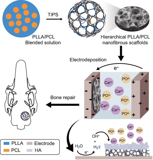 | Scheme 1 Hydroxyapatite-coated PLLA/PCL hierarchical nanofibrous scaffold fabricated via a one-pot thermally induced phase separation (TIPS ) and electrochemical deposition (ED) technique.Abbreviations: HA, hydroxyapatite; PLLA, poly(l-lactic acid); PCL, poly(ε-caprolactone). |
Material and methods
Materials
Poly(ε-caprolactone) (PCL) (MW: 80,000) and poly(l-lactic acid (PLLA) (1.93 dL/g of inherent viscosity) were purchased from Daigang Biomaterials, Inc. (Jinan, China). Dulbcco’s modified eagle’s medium/nutrient mixture F-12 (DMEM/F-12), fetal bovine serum), penicillin, streptomycin, and phosphate-buffered saline (PBS) were obtained from Gibco (Grand Island, USA). The protein quantification (BCA) and alkaline phosphatase (ALP) kits were produced from Beyotime Institute of Biotechnology (Shanghai, China). The kits used in the qPCR experiments were all from the HieffTM series products from Yeasen biotech Co., Ltd. (Shanghai, China). The primers were designed from the NCBI database and then synthesized by a Sangon Biotech Co., Ltd. (Shanghai, China). The Sprague-Dawley (SD) rats used in this study were purchased from SLAC Laboratory Animal, Co., Ltd. (Shanghai, China). The experimental water was filtered through a Millipore ultrapure water system with a resistivity of 18.2 MΩ-cm. Other laboratory reagents were obtained from Aladdin Chemistry, Co., Ltd. (Shanghai, China) without special notification.
Preparation of the hierarchical PLLA/PCL porous scaffold
The hierarchical PLLA/PCL porous scaffold was prepared by one-pot TIPS. Typically, 1 g PLLA and PCL (mass ratio of 70:30) were weighed and dissolved in 10 mL tetrahydrofuran. The solution was then constantly stirred at 60°C for 3–4 hrs for complete dissolution to produce a transparent solution with a concentration of 10% (w/v). Subsequently, the above solution was quickly introduced into a Teflon mold which had been preheated to 60°C (note that air bubbles should be avoided at this step), and the Teflon mold was placed in an −80°C freezer overnight. The next day, the casted gelatinous polymer was removed from the mold and cut into a 0.2 cm-thick scaffold. The scaffolds were submerged in an ice-cold deionized water bath at 0°C for solvent exchange for 3 days. The water was changed every 2 days. Finally, the prepared scaffolds were removed from the water bath and lyophilized for 24 hrs to obtain the hierarchical PLLA/PCL nanofibrous scaffolds.
Mineralization of the PLLA/PCL porous scaffold
The mineralization of the PLLA/PCL scaffold was performed in a three-electrode system with a constant voltage. A solution containing 0.025 mol/L of NH4H2PO4 and 0.042 mol/L of Ca(NO3)2 with a pH of 4.7 was prepared as the electrolyte. Before the mineralization, the PLLA/PCL porous scaffold (15 mm in diameter and 2 mm in thickness) was placed in the ethanol, followed by repeated evacuation to remove residual air from the scaffold. The scaffold was then fixed on a stainless-steel plate that served as the cathode, and the platinum electrode was used as the anode. The saturated calomel electrode was selected as the reference electrode in this experiment. All three electrodes were placed in the prepared electrolyte, and the CHI660D electrochemical station was used for electrodeposition (Shanghai Chenhua Yi Qi Ltd.). During the mineralization process, the temperature was set to 37°C. Voltage and time are adjusted to the assigned values. After deposition, the electrodes were removed from the electrolyte and rinsed with distilled water. The water on the surface of the electrode was wiped away using filter paper. After drying at room temperature, the scaffold was detached from the electrode sheet and placed in a vacuum desiccator prior to the next test.
Characterization
The surface topography of the scaffolds was observed by scanning electron microscopy (SEM, JEOL, JSM-6701F) with an acceleration voltage of 10 kV at high vacuum. XRD patterns of the samples were verified by using a D/MAX-2550PC (Rigaku Inc., Japan) diffractometer with Cu K-alpha radiation (λ=1.5405 nm) at a 2θ ranging from 5° to 65°. The element distribution and abundance on the scaffold surface were analyzed by electron dispersive spectrometry (EDS, JEOL JSM-6701F) in conjunction with SEM. The pore diameter was measured and statistically analyzed based on the SEM images. Typically, 40 pores are randomly selected from SEM images for measurement. Each sample was measured three times, and each measurement was tested by three different persons to avoid subjective errors. The compressive testing of scaffolds was conducted using a universal material tester (H5K-S, Hounsfield, UK) with a 200 N load cell. The samples were resized into cylinders with a diameter of about 5 mm and a height of about 10 mm before testing. A cross-head speed of 1 mm/min was applied. At least six specimens were tested for each sample.
Cell culture and seeding
The rat bone marrow stromal cell (rBMSCs) were isolated according to our previous report.22 rBMSCs on their third passage were used for each of the following experiments. The osteogenic medium for rBMSCs was prepared by mixing the growth medium with 100 nM dexamethasone, 10 mM b-glycerophosphate, and 0.05 mM ascorbic acid. Before the cell culture, all samples were sterilized by epoxyethane. The scaffolds were first fixed in a 24-well cell culture plate with a stainless-steel ring on it. A 400 μL rBMSCs cell suspension (3×10⁵ cells/mL for proliferation test and 1.2×10⁶ cells/mL for adhesion test) was then seeded on each scaffold. Finally, the plate was transferred to an incubator with a humidified atmosphere of 5% CO2 at 37°C. Cell culture medium was changed every 2 days.
Cell adhesion and proliferation experiment
The adhesion and proliferation of rBMSCs on the scaffolds were evaluated using a Cell Counting Kit-8 (CCK-8) assay. After a predetermined time of adhesion and proliferation, the cell number could be measured by CCK-8 according to the manufacturer’s protocol. The cell adhesion and proliferation on the scaffold were presented as an optical density (OD) value for CCK-8 test. The morphology of rBMSCs grown on the scaffolds was observed via SEM. After 7-day culture, the cells were first fixed with 2.5% glutaraldehyde for 2 hrs. The treated cells were then washed by PBS and then subjected to gradient alcohol dehydration of varying concentrations (30%, 50%, 75%, 80%, 90%, and 100% v/v). The samples were finally freeze-dried for 72 hrs and observed under SEM. The fluorescence of cells on the scaffold was stained by adding 400 μL 600 nM Calcein-AM PBS solution to each well and then incubated for 1 hr. The live cells on the scaffold could be visualized by a Carl Zeiss LSM 700 confocal laser scanning microscope.
Alkaline phosphatase activity and quantitative real-time polymerase chain reaction (qRT-PCR) measurement
For ALP detection, rBMSCs differentiated for 7 days and 14 days were washed three times with PBS. Subsequently, the cell lysate (0.2% Triton X-100) was added to the wells, and the cells were then completely lysed by cell sonicator at 4°C. The lysed mixture was centrifuged at 10,000 rpm for 20 mins. The supernatant was collected for quantification of ALP and total protein. The relative ALP activity was normalized to the protein concentration of each sample.
The expression of osteogenic genes was analyzed by quantitative real-time reverse transcription polymerase chain reaction (qRT-PCR, 7500, Applied Biosystems, Foster City, CA). After 3, 7, and 14 days of differentiation, the mRNA of the cells on the scaffold was extracted using RNeasy Mini Kit (Valencia, CA, USA) and then converted to cDNA by Hieff™ First Strand cDNA Synthesis Kit. The expression level of the target gene is quantified by real-time quantitative PCR technology.
The relative expression level of each gene was standardized based on the expression levels of GAPDH and then calculated using the 2−ΔΔCt method.23 Herein, ΔCt values obtained from rBMSCs cultured on PLLA/PCL porous scaffolds in osteogenic medium for 3, 7, and 14 days served as the controls.
In vivo bone defect repairing efficacy
The animal studies were carried out in compliance with the NIH guidelines for the care and use of laboratory animals (NIH Publication, No. 85-23, Rev. 1985) and approved by the ethics committee in animal experimentation of the Research Center for Laboratory Animal of the Ninth People’s Hospital affiliated with Shanghai Jiao Tong University, School of Medicine, Shanghai, China. In this experiment, 24 SD rats (8 weeks old) were fed with a standard diet and housed individually under a constant temperature environment (23–25°C) with a relative humidity of 40–70%. Illumination was administered with a fluorescent light for a 12 hrs light/12 hrs dark cycle. During the surgery, the rat was anesthetized by 3–5% isoflurane with a face mask. The anesthetized rat was then shaved and fixed on the operating table. Then, a sagittal incision was made at the midline of the scalp of the rat. The skull was exposed with a blunt scraper in dorsal view. An electric drill was used to make round defects (5 mm in diameter) at low speed in the parietal bone with a continuous flush of pre-cooled saline (4°C). Two sets of prepared scaffolds (the PLLA/PCL scaffold and the mineralized PLLA/PCL scaffold) were implanted in the rat skull defects. Finally, the wound was rinsed with 0.9% saline, and the incision was sutured. The entire procedure was performed in a sterilized fume hood.
Mico-CT scanning and histological analysis
After the scaffolds were implanted in rats for 2, 4, and 12 weeks, the rats were sacrificed by an overdose of anesthetics. Scanning was performed on a dual source CT imaging system (Somatom Definition Flash, Simens, Germany). The 3D image reconstruction was performed using Amira 4.1 (FEI, USA) software. Bone mineral density (BMD) and the bone volume (BV) of the defect sites were calculated in the CT test.
For the histological analysis, the samples were first washed with physiological saline and fixed in 4% formalin for 24 hrs. After that, samples were dehydrated with gradient ethanol solutions (70%, 75%, 80%, 85%, 90%, 95%, and 100% v/v) for 1 hr in each concentration. The sample was then permeated and embedded in poly(methyl methacrylate under vacuum at 4°C for 20 days. Sections of 200 μm-thick were cut along the sagittal plane of the rat skull with a hard tissue microtome and subjected to a matte finish down to a thickness of 80 μm. Hematoxylin and eosin (H&E) and Masson staining were performed to assess the formation of new bone tissue. All of the above sections were observed and imaged under an optical microscope after staining.
Statistical analysis
Statistical analyses of the date were carried out using SPSS 17.0 (SPSS Inc., Chicago, IL). One- or two-way analyses of variance was used to determine statistical significance. The difference was considered significant only if the p-value was less than 0.05: * indicates p<0.05, and ** represents p<0.01. All data were shown as the mean value ± standard deviation.
Results and discussion
Morphological observation of the hierarchical PLLA/PCL scaffold
As shown in Figure 1A, the PLLA/PCL nanofibrous scaffold fabricated by TIPS resulted in a white cylinder. There are many methods for preparing three-dimensional nanofibrous scaffolds, such as electrospinning and self-assembly.24 The advantage of TIPS over those methods is that it is more suitable for mass production at relatively lower costs and may make the process faster. Moreover, TIPS is very flexible with respect to the final shape of the prepared scaffold by using different molds.
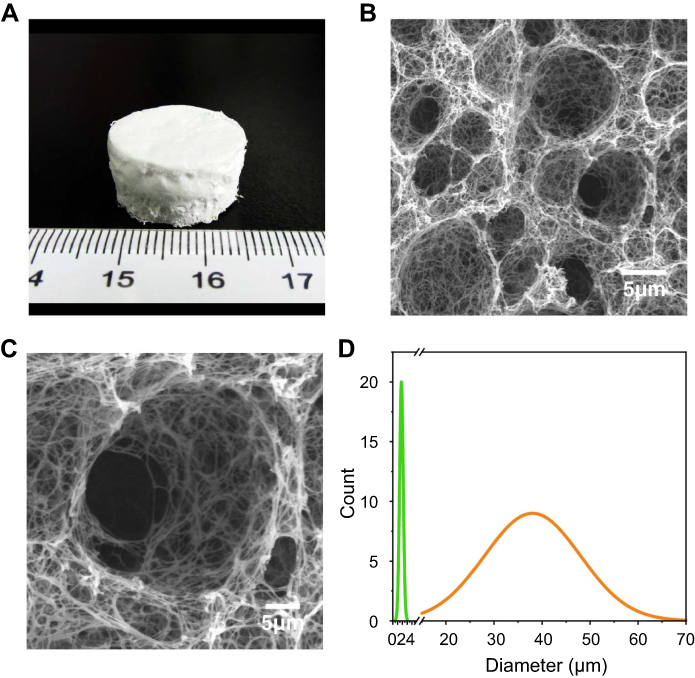 | Figure 1 (A) Photo of PLLA/PCL scaffold. (B) SEM images of PLLA/PCL scaffold (C) a magnified portion of the image (B). (D) The pore size distribution of the PLLA/PCL scaffold. Abbreviations: SEM,scanning electron microscopy;PLLA, poly(l-lactic acid); PCL, poly(ε-caprolactone). |
The morphology of the PLLA/PCL scaffold prepared by TIPS is shown in Figure 1B. All pores were interconnected with nanofibers and showed nanofibrous network in detail (Figure 1C). The average diameter of the nanofibers measured by ImageJ software was 288.10±94.30 nm (Figure 1C). Most importantly, the prepared scaffold exhibits a hierarchical pore size distribution on the microscale with a high peak centering at 37.4 μm, as well as a low peak centering at 1.9 μm (Figure 1D). The size of bone cells ranges from 10 to 50 μm,25,26 indicating that the macropores of the scaffold can well support the penetration of bone cells. The interconnected microporous structures were similar to that in natural bone ECM27 and thus the scaffold would also be highly suitable for cell adhesion and nutrient exchange. The SEM images showed that the prepared PLLA/PCL scaffold had a hierarchical nanofibrous structure, which provides a promising platform for cell growth and new tissue formation.
Effects of mineralization time and voltages on mineralization
The effects of electrodeposition times and voltages on the PLLA/PCL scaffolds are shown in Figure 2. The mineralization effect of electrodeposition time on samples was explored by fixing the voltages at 2 V and changing the mineralization time (1, 2, and 3 hrs). The images of the M-PLLA/PCL scaffolds after mineralization at different time points are shown in Figure 2A–C. After mineral deposition of the scaffold for 1 hr (Figure 2A), some crystals were observed at the edge of the scaffold’s pores. As the time was extended to 2 hrs, the mineralization began to advance into the interior of the scaffold, and the entire scaffold was covered by deposited minerals (Figure 2B). When the mineralization time was increased to 3 hrs, the scaffold was completely covered by spherical crystals due to the continuous formation of new crystal nuclei and the explosive growth of crystals. As a result, the inherent bulk structure of the scaffold could not be observed (Figure 2C).
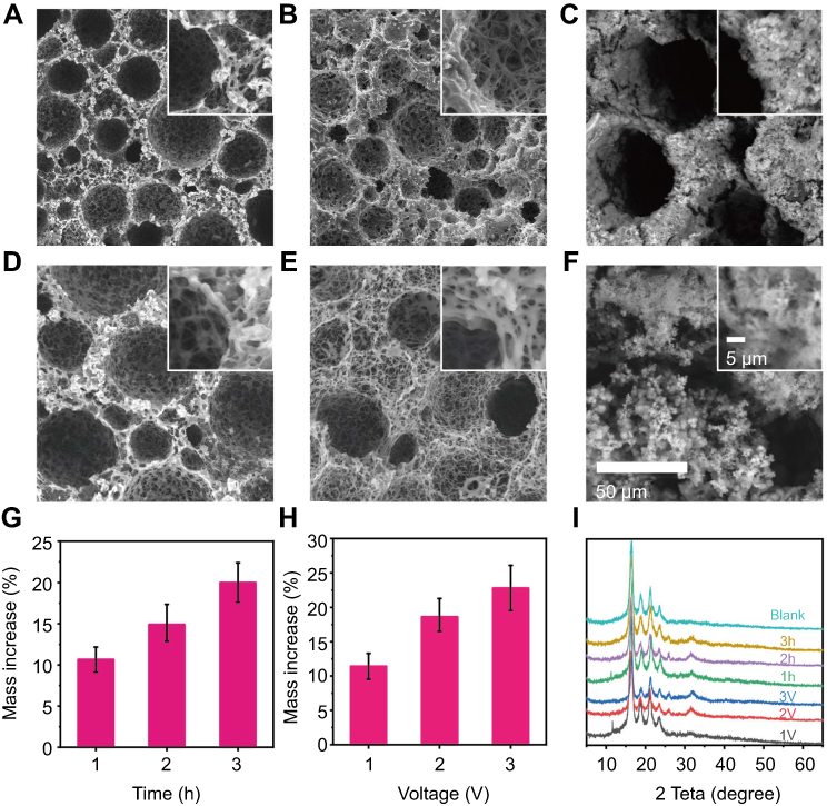 | Figure 2 (A–C) SEM images of mineralized PLLA/PCL scaffold at 37°C and 2 V for: (A) 1 hr, (B) 2 hrs, (C) 3 hrs. (D–F) SEM images of mineralized PLLA/PCL scaffold at 37°C and 2 hrs for (A) 1 V, (B) 2 V, (C) 3 V. The insets are of magnified images, and the magnification of SEM figures and inlets is uniform. (G) Mass increase with different time. (H) Mass increase with different voltage. (I) XRD patterns of the corresponding mineralized PLLA/PCL scaffold.Abbreviations: V, voltage;SEM,scanning electron microscopy;XRD,X-ray diffraction;PLLA, poly(l-lactic acid); PCL, poly(ε-caprolactone). |
The voltage also plays an important role during the mineralization of the scaffold.28 The effects of electrodeposition voltage (1 V, 2 V, and 3 V) were investigated at a fixed electrodeposition time of 2 h. Figure 2D–F shows the SEM images of the mineralized scaffolds at different voltages. At the lowest voltage (1 V), some mineral particles were visible surrounding the scaffold pores (Figure 2D). When the voltage was increased to 2 V, the scaffold was evenly coated with deposited crystals (Figure 2E). As the voltage rose to 3 V, the mineral coating became thicker, and the nanofibrous structure was diminished (Figure 2F).
Figure 2G and H shows the mass changes of scaffold after different electrodeposition time and voltage. When the mineralization time was increased from 1 to 3 hrs, the weight of the scaffold increased by 12.90±2.77 and 19.84±3.84, respectively (Figure 2G). This result indicated that as the deposition time is extended, the mass of mineral crystals on the scaffold is gradually increased. Figure 2H shows that the increased weight of scaffolds was proportional to the increased voltage. When the mineralization voltage was 1 V, the weight of the scaffold increased by 11.40±7.15%. As the voltage was increased to 2 and 3 V, the mass of the scaffold increased by 17.33±2.68% and 22.97±5.28%, respectively. These results demonstrate that the voltage increase can accelerate the mineralization rate of the scaffold, which is in agreement with our previous report.28
XRD results further investigated the structural information of the deposited minerals. Figure 2I shows that the crystal structure was changed with electrodeposition time and the applied voltage. In the 1-hr deposition time, the XRD pattern of the mineralized scaffold exhibited two peaks at a 2θ of 11.7° and 31.9°, which represented the diffraction peak of the (020) crystal plane of dicalcium phosphate dihydrate (DCPD, JCPDS card number: 09-0077) and the (211) crystal plane of hydroxyapatite (HA, JCPDS card number: 09-0432), respectively. When the mineralization time was set to 1 hr, the deposited crystals were mainly composed of DCPD and HA. While the mineralization time was extended to 2 and 3 hrs, the diffraction peak of DCPD disappeared, and the diffraction peaks of HA (2θ=26° and 31.9°) became prominent. These results indicated that the main component of the deposited crystal was HA when the electrodeposition time exceeded 1 hr.
Similarly, at an applied voltage of 1 V, the XRD pattern of the mineralized scaffold showed a typical diffraction peak at 2θ of 11.7°, representing the (020) crystal plane of DCPD (JCPDS card number: 09-0077). When the voltage was increased to 2 and 3 V, the diffraction peaks of HA appeared on the XRD pattern at a 2θ of 26.0° and 31.9°, corresponding to the diffraction peaks of the (002) and (211) crystal planes of HA (JCPDS card number: 09-0432), respectively. This suggests that the composition of the mineralized crystal shifted from DCPD to HA along with the applied voltage increase to 2 V.
To investigate the composition distribution of minerals on the M-PLLA/PCL scaffold, the scaffold with 2 hrs electrodeposited time and 2 V voltage was dissected and analyzed by EDS element mapping. The element maps of Ca and P (Figure S1) revealed a homogeneous distribution of HA on the scaffold. EDS analysis of the scaffold surface further showed that the Ca/P molar ratio of the deposited crystals was 1.72, which is very close to the ratio in hydroxyapatite (1.67). These results indicated that at a voltage of 2 V and a treatment time of 2 hrs, hydroxyapatite could be uniformly deposited on the scaffold without destroying its pore structure.
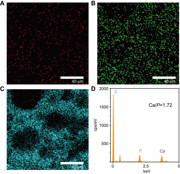 | Figure S1 EDS mapping of the cross-section of the M-PLLA/PCL scaffold. (A) Ca elemental distribution. (B) P elemental distribution. (C) C elemental distribution. (D) The quantitative analysis of the elements on the scaffold.Abbreviations: EDS, electron dispersive spectrometry; PLLA, poly(l-lactic acid); PCL, poly(ε-caprolactone). |
Mechanical properties
Mechanical properties are a critical metric to evaluate the performance of prepared scaffold. The compressive mechanical properties of the scaffolds were studied, and the results are shown in Table S1. The value for ultimate strain in the PLLA/PCL (93.26±4.50) was significantly lower than that in the M-PLLA/PCL (99.75±2.36). Moreover, the compressive modulus of the M-PLLA/PCL is given by 1.134±0.12 MPa, which is significantly larger than that from PLLA/PCL. These results revealed improved mechanical properties after mineralization.
Effect of M-PLLA/PCL scaffold on cell adhesion and proliferation of rBMSCs
The cell adhesion on PLLA/PCL and M-PLLA/PCL scaffolds was studied by CCK tests. As shown in Figure 3A, after 6 hrs of inoculation, the absorbance of the cells on the M-PLLA/PCL scaffold was 0.35±0.041, while the value on the PLLA/PCL scaffold was 0.28±0.029. For the subsequent 6 hrs, each group showed an increase in cell number, but the absorbance on the M-PLLA/PCL scaffold (0.46±0.063) was significantly higher than that of the PLLA/PCL scaffold (0.36±0.043). This result showed that mineralization can effectively increase the adhesion of cells to the scaffold.
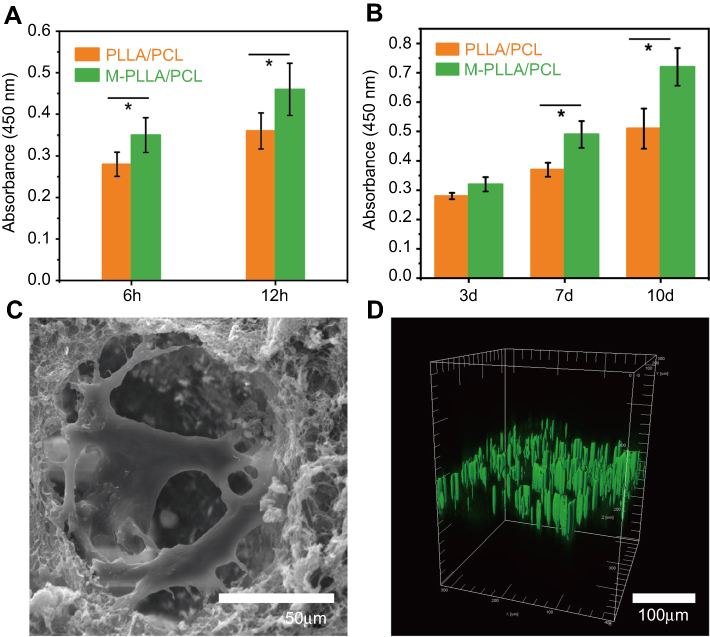 | Figure 3 The rBMSCs adhered (A) and proliferated (B) on the scaffolds, as detected by CCK-8 test. (C) The SEM and (D) confocal tomography of the rBMSCs on the M-PLLA/PCL scaffold after 7 days culture.Abbreviations: rBMSCs, rat bone marrow stromal cells; CCK-8, Cell Counting Kit-8;SEM,Scanning electron microscopy;M-PLLA/PCL, hydroxyapatite- coated hierarchical PLLA/PCL nanofibrous scaffold;PLLA, poly(l-lactic acid); PCL, poly(ε-caprolactone). |
The proliferation of rBMSCs on the scaffold is shown in Figure 3B. On day 3, there was no significant difference between the PLLA/PCL (0.28±0.01) and M-PLLA/PCL (0.32±0.02) groups. After 4 days of growth, the CCK-8 assay showed a significantly increased absorbance in the M-PLLA/PCL group (0.49±0.045) compared to the PLLA/PCL group (0.37±0.02). When the culture period was extended to 10 days, the absorbance on the M-PLLA/PCL scaffold reached to 0.72±0.06, which was significantly higher than that in PLLA/PCL (0.51±0.07). This data demonstrated that the mineralization can provide an enhanced proliferative effect on rBMSCs attached on the scaffold.
The SEM images were used to evaluate the cell morphology on the M-PLLA/PCL scaffold after 7 days of cell culture. Figure 3C shows that after 7 days of culturing, cells adhered to the scaffold and gradually grew toward the inside of the pores. rBMSCs showed a polygonal morphology on the M-PLLA/PCL scaffold. Particularly, cells adhering to the mineralized scaffold showed filopodia, which indicated that rBMSCs on M-PLLA/PCL scaffold were in a good proliferative condition.
Confocal tomography further described the growth state of the cells on the scaffold. As shown in Figure 3D, the cells exhibited a long elliptical shape on the longitudinal section of the scaffold after 7 days of growth. This indicates that cells on the M-PLLA/PCL scaffold could penetrate the interior along with the constructed pores.
The ability of cells to adhere and proliferate on the scaffold is an important indicator for evaluating the in vivo application potential. At this point, experiments were performed to investigate whether the structure and properties of the scaffold were suitable for cell expansion. We investigated the adhesion and growth of cells in porous scaffolds by various methods. Those results demonstrated that the M-PLLA/PCL could not only promote the adhesion and growth of cells on the surface but also provide pores of appropriate size to facilitate the growth of cells toward the interior, thereby promoting tissue reconstruction and regeneration. Due to these positive findings, the material was deemed a promising bone repair material for subsequent experiments.
Osteogenic activity test
ALP is an important biomarker to indicate early osteogenic differentiation.29 Figure 4A shows that rBMSCs grown on the mineralized PLLA/PCL scaffold have a higher level of ALP activity than rBMSCs cultured on a blank PLLA/PCL scaffold after 7 and 14 days of culturing. This suggests that mineralization can improve the osteogenic differentiation of BMSCs, which has been confirmed in previous reports.30
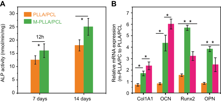 | Figure 4 (A) ALP activity at designated time intervals during osteogenic induction; (B) relative expressions of Col1A1, OCN, RUNX2, and OPN by rBMSCs induced on different scaffolds for 2 weeks. *p<0.05 and **p<0.01.Abbreviations: rBMSCs, rat bone marrow stromal cells; PLLA, poly(l-lactic acid); PCL, poly(ε-caprolactone);M-PLLA/PCL,hydroxyapatite-coated hierarchical PLLA/PCL nanofibrous scaffold. |
The progression of osteogenic differentiation depends on the expression changes of various genes. Previous studies have shown that HA modification on the surface of the material can increase the expression of osteogenic-related genes.31 To further investigate the osteogenic activity of the scaffold after electrodeposition, some typical osteogenic-related genes (Runx2, Col1A1, OCN, and OPN) were detected at different time points (3, 7, and 14 days). The result is shown in Figure 4B. Four marker gene expressions of rBMSCs on M-PLLA/PCL scaffolds were up-regulated compared with that on the PLLA/PCL scaffolds at 7 and 14 days of osteogenic differentiation. Overall, the results indicated that the mineralization of PLLA/PCL scaffold can enhance the osteogenic differentiation of rBMSCs.
Mico-CT scan analysis
Micro-CT scans were used to analyze the repairing effects of the implanted scaffolds on the skull defects. As shown in Figure 5A, the sagittal image shows no significant difference between PLLA/PCL and M-PLLA/PCL scaffolds after 2 weeks implantation. By 4 weeks, some new bone was formed in the M-PLLA/PCL group, while no significant high-density tissue growth was observed in the PLLA/PCL group. At 12 weeks post-surgery, most of the skull defect area was replenished with regenerated bone in the M-PLLA/PCL group. In contrast, a thin visible layer of new bone was detected in the PLLA/PCL group. Reconstructed 3D images showed a similar trend, where the defect implanted with M-PLLA/PCL group was reduced much quicker than that in the PLLA/PCL group.
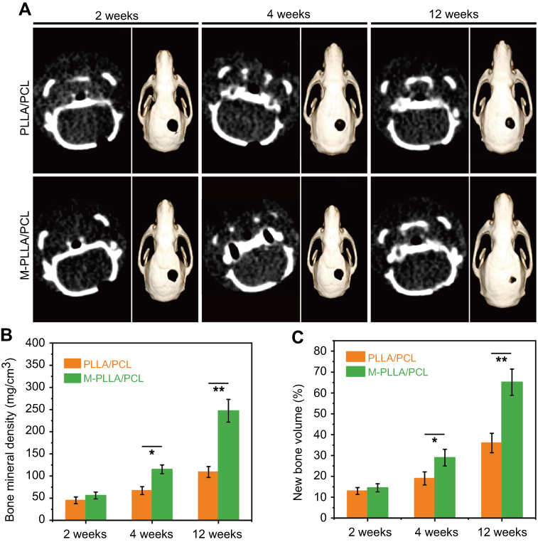 | Figure 5 (A) Micro-CT evaluation (sagittal views and 3D surface rendering) of in vivo calvarial bone healing at 2, 4, and 12 weeks post-implantation for PLLA/PCL and M-PLLA/PCL. (B) The change of bone mineral density (BMD) after the scaffold implantation. (C) The change in bone volume (BV) after the scaffold implantation.(* p<0.05 and ** p<0.01)Abbreviations: rBMSCs, rat bone marrow stromal cells; PLLA, poly(l-lactic acid); PCL, poly(ε-caprolactone);M-PLLA/PCL,hydroxyapatite-coated hierarchical PLLA/PCL nanofibrous scaffold. |
For quantitative analysis of the micro-CT results, the BMD and the BV of newly formed tissue in each defect at different time intervals were calculated. For BMD analysis (Figure 5B), the BMD of the M-PLLA/PCL scaffold was 56 mg/cm3 at 2 weeks and increased to 252 mg/cm3 at 12 weeks, while the value for the PLLA/PCL scaffold increased from 45 to 109 mg/cm3. As shown in Figure 5C, the BV of the M-PLLA/PCL group increased from 14.5% to 66% during the peri-implantation period. The corresponding value of the PLLA/PCL group increased from 13% to 36%. This data reveals that the BMD and BV growth rate of the PLLA/PCL group is significantly slower than that for M-PLLA/PCL group, which is consistent with the Micro-CT images. The Micro-CT results demonstrated the enhanced osteogenic activity of the mineralized scaffold for in vivo bone defect repair.
Histological evaluation
The regeneration of new bone at the cranial defect was analyzed by H&E and Masson’s trichrome staining at 12 weeks after scaffold implantation. H&E staining is a classical pathological analysis method which could clearly identify the structure of cells and tissues. By this staining, the nucleus is stained purple, and the cytoplasm is stained red. As shown in Figure 6, the cells have completely penetrated and grown into the scaffold after material implantation. In particular, the architecture of the blood vessels (marked with a pentagram) could also be observed from the analysis. These results were consistent with our previous in vitro experiments, confirming that the prepared hierarchical porous scaffold structure facilitates cell growth and tissue regeneration. Additionally, we did not find significant inflammation or necrosis around the scaffold, indicating its good tissue compatibility in vivo. Further analysis revealed that most of the M-PLLA/PCL scaffold had degraded after 12 weeks implantation and was replaced by new bone with a cortical bone structure (marked with triangles). In contrast, the new tissue in PLLA/PCL scaffold was mainly immature osteoid (marked with squares), which was woven in the defect. The arrow marked the remaining scaffold materials in the defect site. It can be seen that the M-PLLA/PCL degraded faster than the PLLA/PCL after 12 weeks of implantation. This might be due to the accelerated growth of tissue on the mineralized scaffold.
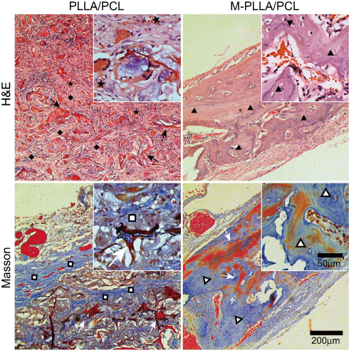 | Figure 6 Histological analysis for in vivo calvaria defect repair. The magnification of figures and inlets is uniform.Abbreviations: PLLA, poly(l-lactic acid); PCL, poly(ε-caprolactone);M-PLLA/PCL,hydroxyapatite-coated hierarchical PLLA/PCL nanofibrous scaffold. |
Masson’s trichrome staining further confirmed the results of H&E staining. In Masson staining, collagen is stained blue, and the density of collagen is positively correlated with depth of the blue coloring. As can be seen from Figure 6, most tissues in the M-PLLA/PCL implant were stained a deep blue, representing the formation of mature bone tissue (marked with hollow triangles). In PLLA/PCL implants, although there are some blue-stained tissues (marked with hollow squares), their densities are significantly lower than those observed in M-PLLA/PCL implants. Moreover, the collagen structure in the PLLA/PCL group is looser than that in the M-PLLA/PCL group. These results show that the implantation of M-PLLA/PCL scaffold not only promotes the infiltration of cells and tissues but also accelerates the remodeling and maturation of new tissues, thereby promoting the healing of damaged sites.
Hierarchical nanofibrous scaffolds are of great importance in bone regeneration. The preparation of such scaffold with tunable pore size has always been a challenge for both researchers and clinicians.3,4 TIPS was an effective method for preparing nanofiber scaffolds.8–10 But it is unsatisfactory to fabricate hierarchical nanofibrous scaffolds in terms of a single TIPS system only. Much of earlier research focused on using various porogens to obtain different pore shape and porosity in TIPS-derived scaffold.12 However, these methods are relatively complicated and tend to decrease the stability of the system, making the polymer phase separation uncontrollable. In this study, a biphasic TIPS system (PLLA/PCL) was used to fabricate the hierarchical nanofibrous scaffold. Pores generated by this system were suitable for rBMSCs growth and penetration. Moreover, the electrodeposition was employed to mineralize the scaffold, thus enhancing the osteoconductivity and osteoinductivity of the scaffold. Compared with previous studies,13,19 we combined biphasic TIPS with electrodeposition to develop a fast, convenient, and effective method to fabricate hydroxyapatite incorporated hierarchical nanofibrous scaffolds.
Conclusions
In summary, the mineralized hierarchical PLLA/PCL nanofibrous scaffold was prepared by one-pot TIPS and in situ electrodeposition at room temperature. The physicochemical properties, cell behavior, and osteoinductive potential of the mineralized were systematically investigated. The pore size of the prepared nanofibrous scaffold was hierarchically distributed so as to match the biophysical structure for osteoblast growth. After electrodeposition at 2 V for 2 hrs, the scaffold coated with hydroxyapatite could be obtained. The M-PLLA/PCL scaffold showed better cell proliferation and osteogenesis activity compared to the PLLA/PCL scaffold. Further in vivo bone repair studies indicated that the M-PLLA/PCL scaffold could accelerate defect healing in 12 weeks, while PLLA/PCL scaffold had little effect on decreasing the size of the bone defect. Postoperative histological examination of the cranial bones also indicated the implantation of M-PLLA/PCL scaffolds can promote bone tissue remodeling and integration. These results show that electrodeposited hierarchical PLLA/PCL scaffolds have great potential for bone repair.
Acknowledgments
This work was financially supported by the National Natural Science Foundation of China (31570984, 31771048, and 81700086), the Fundamental Research Funds for the Central Universities (2232018A3-07), and the Chinese Universities Scientific Fund (CUSFDH-D-2015054). We want to deliver our special thanks to Dr. XinYi Dai for his help in animal experiments and histological analysis.
Disclosure
The authors report no conflicts of interest in this work.
References
1. Yao Q, Cosme JG, Xu T, et al. Three dimensional electrospun PCL/PLA blend nanofibrous scaffolds with significantly improved stem cells osteogenic differentiation and cranial bone formation.Biomaterials. 2017;115:115–127. doi:10.1016/j.biomaterials.2016.11.018
2. Lee J, Kim G. Three-dimensional hierarchical nanofibrous collagen scaffold fabricated using fibrillated collagen and pluronic F-127 for regenerating bone tissue. ACS Appl Mater Interfaces. 2018;10(42):35801–35811. doi:10.1021/acsami.8b14088
3. Xu T, Miszuk JM, Zhao Y, Sun H, Fong H. Bone tissue engineering: electrospun polycaprolactone 3D nanofibrous scaffold with interconnected and hierarchically structured pores for bone tissue engineering. Adv Healthcare Mater. 2015;4(15):2237. doi:10.1002/adhm.201570089
4. Xu Y, Cui W, Zhang Y, et al. Hierarchical micro/nanofibrous bioscaffolds for structural tissue regeneration. Adv Healthcare Mater. 2017;6(13):1601457. doi:10.1002/adhm.201601457
5. Baino F, Fiorilli S, Vitale-Brovarone C. Bioactive glass-based materials with hierarchical porosity for medical applications: review of recent advances. Acta Biomater. 2016;42:18–32. doi:10.1016/j.actbio.2016.06.033
6. Zitnay JL, Reese SP, Tran G, Farhang N, Bowles RD, Weiss JA. Fabrication of dense anisotropic collagen scaffolds using biaxial compression. Acta Biomater. 2018;65:76–87. doi:10.1016/j.actbio.2017.11.017
7. Pei X, Ma L, Zhang B, et al. Creating hierarchical porosity hydroxyapatite scaffolds with osteoinduction by three-dimensional printing and microwave sintering. Biofabrication. 2017;9(4):045008. doi:10.1088/1758-5090/aa90ed
8. Li L, Ge J, Wang L, Guo B, Ma PX. Electroactive nanofibrous biomimetic scaffolds by thermally induced phase separation. J Mater Chem B. 2014;2(36):6119–6130. doi:10.1039/C4TB00493K
9. Bianco A, Burg SL, Parnell AJ, et al. Control of the porous structure of polystyrene particles obtained by nonsolvent induced phase separation. Langmuir. 2017;33(46):13303–13314. doi:10.1021/acs.langmuir.7b02802
10. Liu Y, Sun Q, Wang S, et al. Studies of silk fibroin/poly (lactic-co-glycolic acid) scaffold, prepared by thermally induced phase separation, as a possible wound dressing. Sci Adv Mater. 2016;8(5):1045–1052. doi:10.1166/sam.2016.2693
11. Kim JF, Jung JT, Wang HH, et al. Microporous PVDF membranes via thermally induced phase separation (TIPS) and stretching methods. J Membr Sci. 2016;509:94–104. doi:10.1016/j.memsci.2016.02.050
12. Wang WZ, Nie W, Zhou XJ, et al. Fabrication of heterogeneous porous bilayered nanofibrous vascular grafts by two-step phase separation technique. Acta Biomater. 2018;79:168–181. doi:10.1016/j.actbio.2018.08.014
13. Zhang WY, Zhao Q, Yuan JY. Porous polyelectrolytes: the interplay of charge and pores for new functionalities. Angew Chem Int Ed. 2018;57(23):6754–6773. doi:10.1002/anie.v57.23
14. Dhand C, Ong ST, Dwivedi N, et al. Bio-inspired in situ crosslinking and mineralization of electrospun collagen scaffolds for bone tissue engineering. Biomaterials. 2016;104:323–338. doi:10.1016/j.biomaterials.2016.07.007
15. He CL, Zhang F, Cao LY, et al. Rapid mineralization of porous gelatin scaffolds by electrodeposition for bone tissue engineering. J Mater Chem. 2012;22(5):2111–2119. doi:10.1039/C1JM14631A
16. Yu X, Tang X, Gohil SV, Laurencin CT. Biomaterials for bone regenerative engineering. Adv Healthcare Mater. 2015;4(9):1268–1285. doi:10.1002/adhm.201400760
17. Luo Y, Lode A, Wu C, Chang J, Gelinsky M. Alginate/nanohydroxyapatite scaffolds with designed core/shell structures fabricated by 3D plotting and in situ mineralization for bone tissue engineering. ACS Appl Mater Interfaces. 2015;7(12):6541–6549. doi:10.1021/am508469h
18. Cheng YL, Chen YW, Wang K, Shie MY. Enhanced adhesion and differentiation of human mesenchymal stem cell inside apatite-mineralized/poly (dopamine)-coated poly (ε-caprolactone) scaffolds by stereolithography. J Mater Chem B. 2016;4(38):6307–6315. doi:10.1039/C6TB01377E
19. Lei B, Shin KH, Noh DY, et al. Nanofibrous gelatin–silica hybrid scaffolds mimicking the native extracellular matrix (ECM) using thermally induced phase separation. J Mater Chem. 2012;22(28):14133–14140. doi:10.1039/c2jm31290e
20. Xie C, Lu X, Wang K, et al. Pulse electrochemical driven rapid layer-by-layer assembly of polydopamine and hydroxyapatite nanofilms via alternative redox in situ synthesis for bone regeneration. ACS Biomater Sci Eng. 2016;2(6):920–928. doi:10.1021/acsbiomaterials.6b00015
21. He CL, Xiao G, Jin X, Sun C, Ma PX. Electrodeposition on nanofibrous polymer scaffolds: rapid mineralization, tunable calcium phosphate composition and topography. Adv Funct Mater. 2010;20(20):3568–3576. doi:10.1002/adfm.201000993
22. Nie W, Peng C, Zhou XJ, et al. Three-dimensional porous scaffold by self-assembly of reduced graphene oxide and nano-hydroxyapatite composites for bone tissue engineering. Carbon. 2017;116:325–337. doi:10.1016/j.carbon.2017.02.013
23. Fernandes JS, Gentile P, Martins M, et al. Reinforcement of poly-l-lactic acid electrospun membranes with strontium borosilicate bioactive glasses for bone tissue engineering. Acta Biomater. 2016;44:168–177.
24. He CL, Nie W, Feng W. Engineering of biomimetic nanofibrous matrices for drug delivery and tissue engineering. J Mater Chem B. 2014;2(45):7828–7848. doi:10.1039/C4TB01464B
25. Choi MG, Koh HS, Kluess D, et al. Effects of titanium particle size on osteoblast functions in vitro and in vivo. Proc Natl Acad Sci. 2005;102(12):4578–4583. doi:10.1073/pnas.0500693102
26. Izquierdo-Barba I, García-Martín JM, Álvarez R, et al. Nanocolumnar coatings with selective behavior towards osteoblast and Staphylococcus aureus proliferation. Acta Biomater. 2015;15:20–28. doi:10.1016/j.actbio.2014.12.023
27. Kim IG, Hwang MP, Du P, et al. Bioactive cell-derived matrices combined with polymer mesh scaffold for osteogenesis and bone healing. Biomaterials. 2015;50:75–86. doi:10.1016/j.biomaterials.2015.01.054
28. He CL, Jin X, Ma PX. Calcium phosphate deposition rate, structure and osteoconductivity on electrospun poly (L-lactic acid) matrix using electrodeposition or simulated body fluid incubation. Acta Biomater. 2014;10(1):419–427. doi:10.1016/j.actbio.2013.08.041
29. Faia-Torres AB, Charnley M, Goren T, et al. Osteogenic differentiation of human mesenchymal stem cells in the absence of osteogenic supplements: a surface-roughness gradient study. Acta Biomater. 2015;28:64–75. doi:10.1016/j.actbio.2015.09.028
30. Yang M, Shuai Y, Zhang C, et al. Biomimetic nucleation of hydroxyapatite crystals mediated by Antheraea pernyi silk sericin promotes osteogenic differentiation of human bone marrow derived mesenchymal stem cells. Biomacromolecules. 2014;15(4):1185–1193. doi:10.1021/bm401740x
31. Chen W, Shen X, Hu Y, et al. Surface functionalization of titanium implants with chitosan-catechol conjugate for suppression of ROS-induced cells damage and improvement of osteogenesis. Biomaterials. 2017;114:82–96. doi:10.1016/j.biomaterials.2016.10.055
Supplementary materials
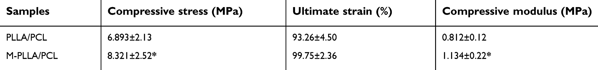 | Table S1 Mechanical properties of the M-PLLA/PCL and PLLA/PCL (*p<0.05) |
 © 2019 The Author(s). This work is published and licensed by Dove Medical Press Limited. The full terms of this license are available at https://www.dovepress.com/terms.php and incorporate the Creative Commons Attribution - Non Commercial (unported, v3.0) License.
By accessing the work you hereby accept the Terms. Non-commercial uses of the work are permitted without any further permission from Dove Medical Press Limited, provided the work is properly attributed. For permission for commercial use of this work, please see paragraphs 4.2 and 5 of our Terms.
© 2019 The Author(s). This work is published and licensed by Dove Medical Press Limited. The full terms of this license are available at https://www.dovepress.com/terms.php and incorporate the Creative Commons Attribution - Non Commercial (unported, v3.0) License.
By accessing the work you hereby accept the Terms. Non-commercial uses of the work are permitted without any further permission from Dove Medical Press Limited, provided the work is properly attributed. For permission for commercial use of this work, please see paragraphs 4.2 and 5 of our Terms.