")
Back to Journals » International Journal of Nanomedicine » Volume 15
Physical–Chemical Crosslinked Electrospun Colocasia esculenta Tuber Protein–Chitosan–Poly(Ethylene Oxide) Nanofibers with Antibacterial Activity and Cytocompatibility
Authors Wardhani RAK , Asri LATW , Rachmawati H, Khairurrijal K , Purwasasmita BS
Received 15 May 2020
Accepted for publication 16 July 2020
Published 25 August 2020 Volume 2020:15 Pages 6433—6449
DOI https://doi.org/10.2147/IJN.S261483
Checked for plagiarism Yes
Review by Single anonymous peer review
Peer reviewer comments 3
Editor who approved publication: Dr Phong A Tran
Riesca Ayu Kusuma Wardhani,1 Lia ATW Asri,2 Heni Rachmawati,3,4 Khairurrijal Khairurrijal,5,6 Bambang Sunendar Purwasasmita1,4
1Advanced Materials Processing Group, Engineering Physics Study Program, Institut Teknologi Bandung, Bandung 40132, Indonesia; 2Materials Science and Engineering Research Group, Faculty of Mechanical and Aerospace Engineering, Institut Teknologi Bandung, Bandung 40132, Indonesia; 3School of Pharmacy, Institut Teknologi Bandung, Bandung 40132, Indonesia; 4Research Center for Nanosciences and Nanotechnology, Institut Teknologi Bandung, Bandung 40132, Indonesia; 5Physics of Electronic Materials Division, Physics Study Program, Institut Teknologi Bandung, Bandung 40132, Indonesia; 6Bioscience and Biotechnology Research Center, Institut Teknologi Bandung, Bandung 40132, Indonesia
Correspondence: Bambang Sunendar Purwasasmita
Advanced Materials Processing Group, Engineering Physics Study Program, Institut Teknologi Bandung, Bandung 40132, Indonesia
Tel +62-22-2534174
Email [email protected]
Lia ATW Asri
Materials Science and Engineering Research Group, Faculty of Mechanical and Aerospace Engineering, Institut Teknologi Bandung, Bandung 40132, Indonesia
Tel +62-22-2534174
Email [email protected]
Background: Electrospun nanofibers based on Colocasia esculenta tuber (CET) protein are considered as a promising material for wound dressing applications. However, the use of these nanofibers in aqueous conditions has poor stability. The present study was performed to obtain insights into the crosslinked electrospun CET’s protein–chitosan (CS)–poly(ethylene oxide) (PEO) nanofibers and to evaluate their potential for wound dressing applications.
Methods: The electrospun nanofibers were crosslinked with glutaraldehyde (GA) vapor and heat treatment (HT) to enhance their physicochemical stability. The crosslinked nanofibers were characterized by protein profiles, morphology structures, thermal behavior, mechanical properties, and degradation behavior. Furthermore, the antibacterial properties and cytocompatibility were analyzed by antibacterial assessment and cell proliferation.
Results: The protein profiles of the electrospun CET’s protein–CS–PEO nanofibers before and after HT crosslinking contained one major bioactive protein with a molecular weight of 14.4 kDa. Scanning electron microscopy images of the crosslinked nanofibers indicated preservation of the structure after immersion in phosphate buffered saline. The crosslinked nanofibers resulted in higher ultimate tensile strength and lower ultimate strain compared to the non-crosslinked nanofibers. GA vapor crosslinking showed higher water stability compared to HT crosslinking. The in vitro antibacterial activity of the crosslinked nanofibers showed a stronger bacteriostatic effect on Staphylococcus aureus than on Escherichia coli. Human skin fibroblast cell proliferation on crosslinked GA vapor and HT nanofibers with 1% (w/v) CS and 2% (w/v) CET’s protein demonstrated the highest among all the other crosslinked nanofibers after seven days of cell culture. Cell proliferation and cell morphology results revealed that introducing higher CET’s protein concentration on crosslinked nanofibers could increase cell proliferation of the crosslinked nanofibers.
Conclusion: These results are promising for the potential use of the crosslinked electrospun CET’s protein–CS–PEO nanofibers as bioactive wound dressing materials.
Keywords: Colocasia esculenta, chitosan, crosslinking, electrospun nanofibers, poly(ethylene oxide), wound dressing
Introduction
Wound healing is a complex regeneration process that involves several biological and molecular systems, such as coagulation, inflammation, proliferation-migration, and remodeling, to restore normal biological function.1 The wound dressing is generally used as a protector for wounds against infection or external exposure.2 Most of the wound dressing still use gauze. Nevertheless, gauze only protects wounds from external exposure by providing a dry environment and no bioactive molecules or antibacterial substances. This wound dressing also needs to be replaced every 12–24 h, which causes disruption of healthy tissue growth and causes pain in the patient.3,4 Therefore, the nanofiber membrane is the choice for wound dressing because of its functional versatility, such as being able to mimic the fibrous architecture of natural extracellular matrix (ECM) for support cell attachment and proliferation, permeable to water vapor and oxygen, providing an effective barrier against bacteria or other microorganisms. Moreover, nanofiber membranes can be fabricated from various biodegradable materials with the addition of antibacterial substances or bioactive molecules.5 Bioactive molecules such as proteins can encourage fibroblast activity and endothelial cell migration, increasing the wound healing process.5 Protein is one of the essential roles in the wound healing process because it is needed for enzyme and collagen synthesis, the proliferation of fibroblast cells, and the formation of connective tissue. They significantly affect all stages of wound healing.6–8
Colocasia esculenta is an edible plant originating from Asia (Japan, Indonesia, China, etc.) that grows in tropical and sub-tropical areas.9,10 Colocasia esculenta tuber (CET) provides multiple nutrition components, such as proteins, carbohydrates, vitamins, minerals, and fibers.10 These proteins have been reported to have important biological properties that have been indicated on lectin subunits.11–13 Pereira et al11 have demonstrated that lectins interact with carbohydrates from the surface of hematopoietic cells, leading to cell proliferation of mice splenocyte. Additionally, lectins in the CET’s protein have also provided the in vitro and in vivo immunostimulatory potential.13–15 Wardhani et al16 demonstrated that electrospun CET’s protein–CS–PEO nanofibers have enhanced NIH–3T3 fibroblast cell growth. The highest nutrient content of amino acids in CET’s protein has been reported as arginine.16 These amino acids play a key role in wound healing. Arginine is an amino acid that acts for protein synthesis, stimulates cellular growth, and hormone secretion.6,7,17 Therefore, CET’s proteins are an advantageous material for use as the protein component, in which protein is the main component of the native skin extracellular matrix (ECM) structure.
One of the natural polysaccharides with a broad spectrum of high killing rate against Gram-positive and Gram-negative bacteria is chitosan.18 Chitosan (CS) is a deacetylated derivative of chitin. It has unique characteristics, such as the structural similarity to the glycosaminoglycans found in the ECM, outstanding biocompatibility, appropriate biodegradability, having antibacterial properties, and nontoxicity.19 However, natural polymers have weak mechanical strength. A combination of synthetic polymers is an applicable method to ensure the mechanical properties of natural polymers.5 Furthermore, poly(ethylene oxide) (PEO) is a water-soluble synthetic polymer with good biocompatibility and low toxicity.20
In this work, three biocompatible, biodegradable, and nontoxic polymers selected were two natural polymers (CET’s protein and CS) and one of synthetic polymer (PEO). These choices were encouraged by the promising properties of these polymers, which similarity toward structural components of ECM. All three polymers are fabricated in a three-dimensional structure using electrospinning techniques. Electrospinning is the most efficient processing method for producing continuous nanofiber for large scale from various polymers with small pore size, high porosity, and the sizeable surface-area-to-volume ratio.21,22 This method utilizes electrostatic forces to generate fine fibers with diameters in the nanoscale or microscale range. The desired electrospun fiber properties can be adjusted with solution parameters (polymer concentration, solvent volatility, and solution conductivity) and processing parameters (applied voltage, flow rate, and capillary-collector distance).23,24 The high porosity and high surface area to volume ratio of electrospun fibers make them potentially for wound dressing application due to providing favorable conditions for cell interactions.5
However, nanofiber membranes lose their fiber structure when exposed to aqueous conditions. Structural instability of fiber membranes is due to polymers forming water-based soluble fiber membranes. Several crosslinking techniques are used to overcome these limitations. These include chemical crosslinking, like glutaraldehyde vapor (GA) and physical crosslinking, such as heat treatment (HT). Crosslinking provides the desired improvements in the stability under aqueous environment and mechanical properties.25 GA is the most practical crosslinking agent to crosslink biopolymers because it can react with functional groups in both proteins and carbohydrates. GA vapor crosslinking occurs by creating covalent bonds between the chains of the polymers.25 Additional treatment by blocking unreacted aldehyde groups and washing on crosslinked nanofiber needs to be completed to reduce the risk of toxicity from unreacted GA left in the nanofiber. HT is a physical process where high temperature is applied under vacuum. HT holds the polymer chains by non-covalent bonds such as hydrogen bonding, electrostatic interactions, or other intermolecular forces.25
Some investigations have reported successful development of electrospun CS–PEO nanofibers by adding other polymers intended for wound dressing applications. For instance, electrospun type I collagen–CS–PEO nanofibers can induce migration and proliferation of NIH-3T3 fibroblast cells.26 In another study, electrospun humans like collagen (recombinant E. coli)–CS–PEO nanofibers can support the growth of bone marrow stromal cells and provide good biocompatibility in mice.27 In both studies, the crosslinking of nanofiber membranes also still uses chemical crosslinking through GA vapor. Besides, there have been few studies on crosslinking with safe and simple methods through HT on electrospun nanofibers. Cay et al showed that HT crosslinking at 180 °C produced better structural stability than GA vapor crosslinking on CS–PVA nanofibers.28 Furthermore, HT crosslinking at temperatures of 40, 60, 80, 100, and 145 °C on rhodamine B–CS–PEO could enhance the antibacterial activity, thermal stability, and mechanical properties.29 The electrospun CET studies have reported successfully prepared from solutions CS–PEO. However, the hardly electrospinnable of CET makes a small number of beads are still found in nanofibers.30 Water-soluble proteins extracted from CET is expected to improve the efficacy of CET for an easier electrospinning process. The fabrication of electrospun CET’s protein–CS–PEO nanofibers with the optimization of processes and solutions resulted in smoother fibers.16 According to the literature, no studies considered the physicochemical characteristics with the evaluation of antibacterial activity and cytocompatibility of electrospun CET’s protein–CS–PEO nanofibers for wound dressing applications.
In this study, we aimed to invent a biomimetic system in the form of a nanofiber membrane with excellent material stability. Suitability of the use of crosslinking and bioactive molecules such as CET’s protein is expected that the CET’s protein–CS–PEO nanofibers can effectively function as potential candidates for wound dressing. Schematic illustration of the main experimental process, crosslinking of the nanofibers, the mode of action of GA vapor and HT crosslinking, and the application of the nanofiber membrane on skin wound site have been illustrated in Figure 1.
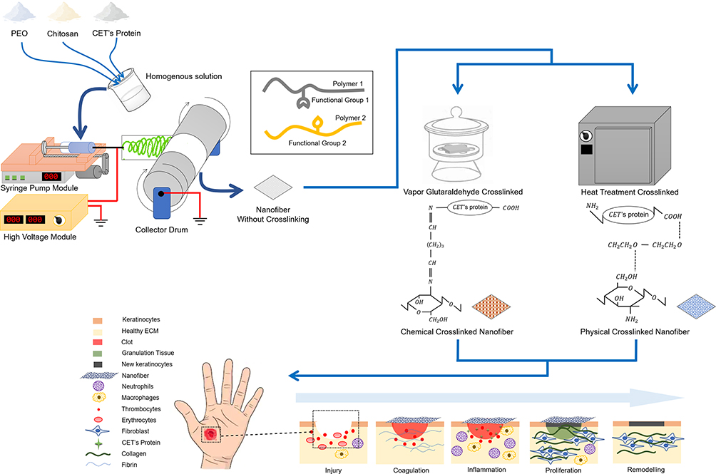 |
Figure 1 Schematic illustration of the preparing electrospun nanofibers, crosslinking of the nanofibers, the mode of action of crosslinking, and the applying of nanofibers as a wound dressing. Notes: Heat treatment crosslinked illustration only shows parts of hydrogen bonding. Functional groups that can form hydrogen bonding in nanofibers are polyether groups in PEO, amine (NH2) and terminal carboxylates (–COOH) in CET’s protein, and amine (NH2) and hydroxyl (OH) in chitosan.Abbreviations: PEO, poly(ethylene oxide); CET’s protein, Colocasia esculenta tuber protein; ECM, extracellular matrix. |
Materials and Methods
Materials
Colocasia esculenta tuber (CET) powder was obtained from PT. Sentra Biogen Bandung, Indonesia. Poly(ethylene oxide) (PEO, average Mw = 600 kDa), chitosan (CS, ≥ 75% deacetylation degree), bovine serum albumin (BSA), and trypan blue solution were purchased from Sigma Aldrich (Saint Louis, MO, USA). Glacial acetic acid, ethanol, glycine, glutaraldehyde (GA, 25% solution in H2O), Muller Hinton Agar, and Muller Hinton Broth were purchased from Merck (Darmstadt, Germany). Low-molecular-weight marker protein was purchased from GE Healthcare (Little Chalfont, UK). Minimum Essential Medium (MEM), penicillin-streptomycin, fetal bovine serum (FBS), trypsin-EDTA, fungizone amphotericin, gentamicin, phosphate buffered saline (PBS), antibiotic, and antimycotic were purchased from Gibco (Grand Island, USA). Human skin fibroblast cell line (BJ cell, ATCC CRL-2522), Gram-positive Staphylococcus aureus (S. aureus, ATCC 6538), and Gram-negative Escherichia coli (E. coli, ATCC 8939) were purchased from American Type Culture Collection (Rockville, MD, USA). PrestoBlue reagent was purchased from Invitrogen (Carlsbad, CA).
CET’s Protein Isolation
Twenty grams of CET powder was dissolved in 600 mL deionized water and stirred overnight at RT. This suspension was centrifuged at a 5000 rpm for 5 min. The supernatant was freeze-dried. The CET’s protein powder was stored at −20 °C until use.
Electrospinning of CET’s Protein–CS–PEO Blend Solution
The various weight percent of CET’s protein, CS, and PEO powders (Table 1) were dissolved in 10% (v/v) acetic acid by stirring overnight at RT to ensure complete dissolution of the polymers. All the solutions were freshly prepared in the electrospinning process. All nanofibers were produced in a horizontal setup electrospinning apparatus (Nachriebe 600, Indonesia), including a high voltage DC power supply, a syringe pump, a 10 mL syringe attached to a 22G blunt-tip needle, and grounded aluminum plate, as a collector. The polymer solutions were electrospun at a high voltage of 18 kV, a flow rate of 1 mL/h, and the distance between the needle tip to the drum collector at 12 cm. At the time of the electrospinning experiment, relative humidity (RH) and temperature values ranged around 35–45% RH and 25–35 °C, respectively.
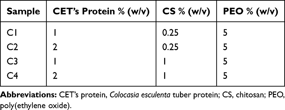 |
Table 1 Composition of Electrospinning Solution |
Crosslinking Methods
The HT and GA vapor were selected as physical and chemical crosslinking methods for stabilizing the electrospun CET’s protein–CS–PEO nanofibers in water. For the HT crosslinking method, the electrospun nanofibers were heated in a vacuum oven at 35–40 °C for 1 h. This temperature was chosen in CET’s protein because the temperature below 41 °C was considered safe and will not break the protein’s interactions and denature them. Crosslinking with GA vapor was carried out by placing the electrospun nanofibers in a sealed desiccator containing 5 mL of 25% GA aqueous solution in a petri dish for 12 h at RT. After crosslinking, the electrospun nanofibers were treated in a 0.2 M glycine solution to block unreacted aldehyde groups for 24 h at RT. They were then rinsed repeatedly in ethanol solution and deionized water. The GA vapor crosslinked electrospun nanofibers were dried at RT and stored in a desiccator for a later test.
Characterization
CET’s protein content in the CET powder, electrospun CET’s protein–CS–PEO nanofibers before and after crosslinking was analyzed using a method of Bradford.31 BSA was used as a reference standard, and the absorbance of the electrospun nanofibers was measured at 595 nm using a UV/Vis spectrophotometer (Thermo Fisher Scientific, USA).
The protein profiles of the electrospun CET’s protein–CS–PEO nanofibers before and after crosslinking were analyzed by sodium dodecyl sulfate-polyacrylamide gel electrophoresis (SDS-PAGE) in 12% polyacrylamide gel under denaturing and reducing conditions. The polypeptide bands were visualized by staining the gels with coomassie brilliant blue R-250.32 Molecular masses of the polypeptide bands were estimated by comparison to the standard protein markers (LMW marker, 14.4–116 kDa) (PageRuler™ Pierce Unstained Protein Molecular Weight Marker, Thermo Scientific, USA).
The morphology structures of the differentially crosslinked electrospun CET’s protein–CS–PEO nanofibers were studied under Scanning Electron Microscope (SEM, Hitachi™, SU-3500, Japan) at an accelerating voltage of 5 kV, after sputter coating with gold (MC-1000, Hitachi™, Japan). The average diameters of the samples were analyzed from the SEM images using CAD software.
The thermal behavior of the various samples was investigated by thermo-gravimetric analysis (TGA, Linseis STA PT 1600, Germany) by heating the samples from room temperature to 350 °C at the rate of 10 °C min−1. Measurements were performed on CET’s protein powder, CS powder, PEO powder, and crosslinked electrospun CET’s protein–CS–PEO nanofibers.
The mechanical properties of the non-crosslinked and crosslinked electrospun CET’s protein–CS–PEO nanofibers (n = 5 for each group) were determined using a tensile testing machine (Textechno Favigrab, Germany). The load cell capacity used is 1 N for all samples except C3–GA and C4–GA samples (C3–GA and C4–GA samples use 100 N load cells). Test specimens of dimensions 25 × 3 mm2, were tested at a crosshead speed of 3 mm min−1 and gauge length of 10 mm under ambient conditions.
The degradation behavior of the crosslinked electrospun CET’s protein–CS–PEO nanofibers was determined by monitoring the weight loss. The samples were immersed in a PBS solution (pH = 7.4) at RT for 1, 3, and 7 days. At each time point, the samples were removed from the PBS solution, rinsed several times with deionized water, and dried at RT overnight. The weight loss of the samples was calculated as given in Equation 1, where W0 is the initial weight of the dry samples, and W1 is the dry weight of the samples after water treatment. Each test was repeated three times.

The stabilization performance of the crosslinked electrospun CET’s protein–CS–PEO nanofibers was investigated by observing SEM images after immerging in PBS solution (pH = 7.4). Each sample was immersed in PBS solution for 1, 3, and 7 days and dried at RT overnight. The morphology structures of the samples were observed under SEM at an accelerating voltage of 5 kV, after sputter coating with gold.
Antibacterial Activity Test
The antibacterial activities of the crosslinked electrospun CET’s protein–CS–PEO nanofibers were performed following the AATCC Test Method 100–2012. Bacterial strains were incubated overnight at 37 °C in Muller Hinton Broth. The crosslinked electrospun nanofibers (4 cm2), previously sterilized by UV light, were inoculated with 80 µL suspension of bacterial strain separately at zero contact time and cultured after 1 h. The samples were diluted with 5 mL PBS solution with a concentration of 10−1 – 10−8 in a vial tube. Each concentration dilution was taken as much as 0.5 mL to be put into sterile petri dishes, and MHA solution was poured as much as 15 mL. The plates were incubated at 37 °C overnight. After incubation, the bacteria were observed, and the colonies in each sample were counted. Controls were established in the same conditions by culturing bacteria on the surface of the agar plate without the samples. The percent reduction of bacteria by the samples was calculated using Equation 2, where R is the reduction rate percent and A, B is the number of bacteria recovered from the inoculated the samples after 1 h and at zero contact time, respectively. All the experiments were performed in triplicate.

Culture of Human Skin Fibroblast
BJ cells were cultured in MEM supplemented with 10% FBS and 1% antibiotic and antimycotic in a 75 cm2 cell culture flask at 37 °C in a humidified atmosphere of 5% CO2. The culture medium was replenished every two days. The crosslinked electrospun CET’s protein–CS–PEO nanofibers were prepared on circular glass coverslip (22 mm in diameter), which were placed in 6-well tissue culture plates. They pressed with a glass ring (20 mm in diameter) to ensure complete contact of the samples with the wells. Before BJ cells seeding, the samples were sterilized under UV light, soaked in 70% ethanol for 1 h, rinsed five times with PBS solution, and subsequently immersed in MEM for 1 h. BJ cells were seeded at a density of 100.000 cells/well of 6-well tissue culture plates and cultured for up to seven days. BJ cells on a circular glass coverslip in 6-well tissue culture plates were seeded as control.
Cell Proliferation
Cell proliferation on the crosslinked electrospun nanofibers was determined using the PrestoBlue assay (n = 3 for each assay). After culturing the cells for a period of 1, 3, 5, and 7 days, the samples were rinsed with PBS solution to remove unattached cells and incubated with 10% PrestoBlue reagent in PBS solution for a period of 2 h at 37 °C. The PrestoBlue with PBS solution was transferred to 96-well tissue culture plates. The absorbance was measured at 570 and 600 nm using a Multiskan™ GO Elisa Reader Spectrophotometer (Thermo Fisher Scientific™, USA).
Cell Morphology
The BJ cell morphology was also analyzed using SEM. After 3 and 5 days of seeding the crosslinked electrospun nanofibers with cells, the culture medium was removed from well tissue culture plates, and the samples were rinsed twice with PBS solution. The samples were fixed with 4% GA solution for 1 h at RT. The fixed samples were rinsed with deionized water for 15 min and dehydrated with a series of ethanol concentrations starting from 50%, 70%, 80%, 90%, and 100% (v/v). The dehydrated samples are dried at RT overnight. The samples were coated with a gold sputter, and the cell’s morphology was analyzed using SEM at a voltage of 5 kV.
Statistical Analysis
All the data are presented as mean ± standard deviation (SD). Statistical differences were determined by one-way analysis of variance (ANOVA) using the GraphPad Prism Software (GraphPad Software, Inc., San Diego, CA, USA). Differences were considered statistically significant at p ≤ 0.05.
Results and Discussion
CET’s Protein Content Analysis
The total CET’s protein content of the non-crosslinked, HT crosslinked, and GA vapor crosslinked electrospun CET’s protein–CS–PEO nanofibers was 0.451%, 0.394%, and 0.327% (w/w), respectively. Figure 2 shows the protein profile of the CET powder and the electrospun nanofibers, while the CET powder contained four major groups of polypeptides with an approximate molecular weight of 14.4; 18.4; 25; and 66.2 kDa, respectively. The figure present that the molecular weight of the non-crosslinked and HT crosslinked nanofibers was around 14.4 kDa. However, there was no spot around 14.4 kDa in GA vapor crosslinked nanofibers because protein might be crosslinked to GA or entrapped in the crosslinked matrix. According to Pereira et al,13 the most abundant of the total CET’s protein content is globulin with molecular mass 14 kDa, about 59% of total soluble protein. A previous study demonstrated that the CET’s protein has an in vitro growth-stimulator effect.16 Those effects were accompanied by an increment in NIH–3T3 fibroblast cell growth relates to the concentration of the CET’s protein so that it provided appropriate conditions for cell growth.16
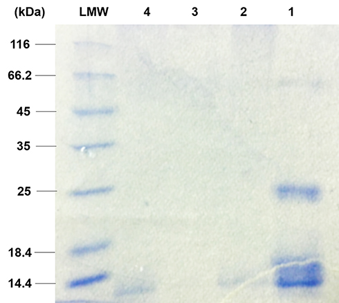 |
Figure 2 The protein profile of (1) CET powder, (2) non-crosslinked nanofibers, (3) GA vapor crosslinked nanofibers, and (4) HT crosslinked nanofibers by SDS-PAGE. Abbreviations: LMW, low molecular weight; CET, Colocasia esculenta tuber; GA, glutaraldehyde; SDS-PAGE, sodium dodecyl sulfate-polyacrylamide gel electrophoresis. |
Morphology of Crosslinked CET’s Protein–CS–PEO Nanofibers
SEM micrographs of the crosslinked electrospun nanofibers with GA vapor (Figure 3A–D), and HT (Figure 3G and H) showed some interconnection at fibers junctions, compact, and stiffer network, whereas in the Figure 3E and F revealed the formation of fused fibers. The morphology of crosslinked nanofibers with HT in the presence of 1% (w/v) CS can maintain the fiber morphology (compare Figure 3E with G and H; F with G and H, respectively). Crosslinked nanofibers of C1–GA, C2–GA, C3–GA, C4–GA, C3–HT, and C4–HT with average diameters in the range of 312 ± 94, 268 ± 52, 255 ± 57, 191 ± 40, 305 ± 85, and 258 ± 92 nm, were respectively obtained. The average diameters of C1–HT and C2–HT was found cannot be measured. The average diameter of crosslinked nanofibers decreased with the increase of CS and CET’s protein concentration. The decrease of fiber diameter was caused by the higher solution conductivity and viscosity based on our previous study.16 The conductivity and viscosity of CS and CET’s protein provide thinner fibers with smaller fibers in the electrospinning process where the polymer solution leads to a greater elongation force under the high electrical field.23,33 The GA vapor of the nanofibers efficiently interlinks between the amino groups of CS with the carbonyl of GA via a Schiff base reaction,16 confirmed by Fourier transform infrared (FTIR) spectra (Figure S1). Also, the amino terminal of the CET’s protein can be crosslinked with the carbonyl of GA. These crosslinking can maintain the fiber structure even after being soaked in water. The HT of the nanofibers induces the release of water content trapped between polymer chains and leads to an increase in the hydrogen bonding or electrostatic interactions between polymer chains.16 The fiber diameters are within the range of ideal properties of nanofibers for wound healing applications (50–500 nm). This diameter sizes mimic of the physical structure of the natural ECM.5
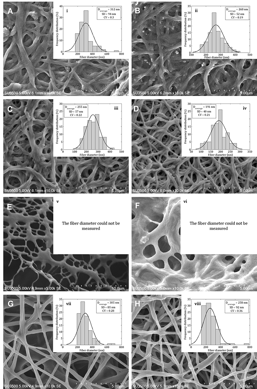 |
Figure 3 Scanning electron microscope images of the crosslinked electrospun (A) C1–GA, (B) C2–GA, (C) C3–GA, (D) C4–GA, (E) C1–HT, (F) C2–HT, (G) C3–HT, (H) C4–HT nanofibers, and fiber diameter distribution of (i) C1–GA, (ii) C2–GA, (iii) C3–GA, (iv) C4–GA, (v) C1–HT, (vi) C2–HT, (vii) C3–HT, (viii) C4–HT nanofibers. Abbreviations: GA, glutaraldehyde; HT, heat treatment. |
Thermal Behavior
The TGA curves from various samples are shown in Figure 4. The TGA curve (Figure 4A) of pure PEO revealed that the mass changes occurred at 217.9–330.5 °C, with a mass loss of about 66.48%. According to the literature, decomposition of PEO begins at around 340–360 °C, with a maximum peak at around 400 °C, reducing in intensity at approximately 420 °C.34,35 In the case of pure CS, it presented two distinct mass changes. In the first stage, the mass changes at 31.7–117.2 °C, with a mass loss at around 10.94%. In the second stage, the mass changes at 246.2–315.5 °C, with a mass loss at around 40.14%. It is seen from the TGA curve of pure CS that the CS decomposition showed two stages: first, the mass loss from initial heating to 130 °C is caused by evaporation and other possible volatile losses; second, the mass loss starting at around 260 °C and appearing a sharp peak at about 300 °C, the mass loss associated with depolymerization and degradation of the CS chain.34 In the pure CET’s protein, the mass changes were observed at 204.2–295.2 °C, with a mass loss of around 27.79%. This mass loss corresponds to the CET’s protein degradation temperature.
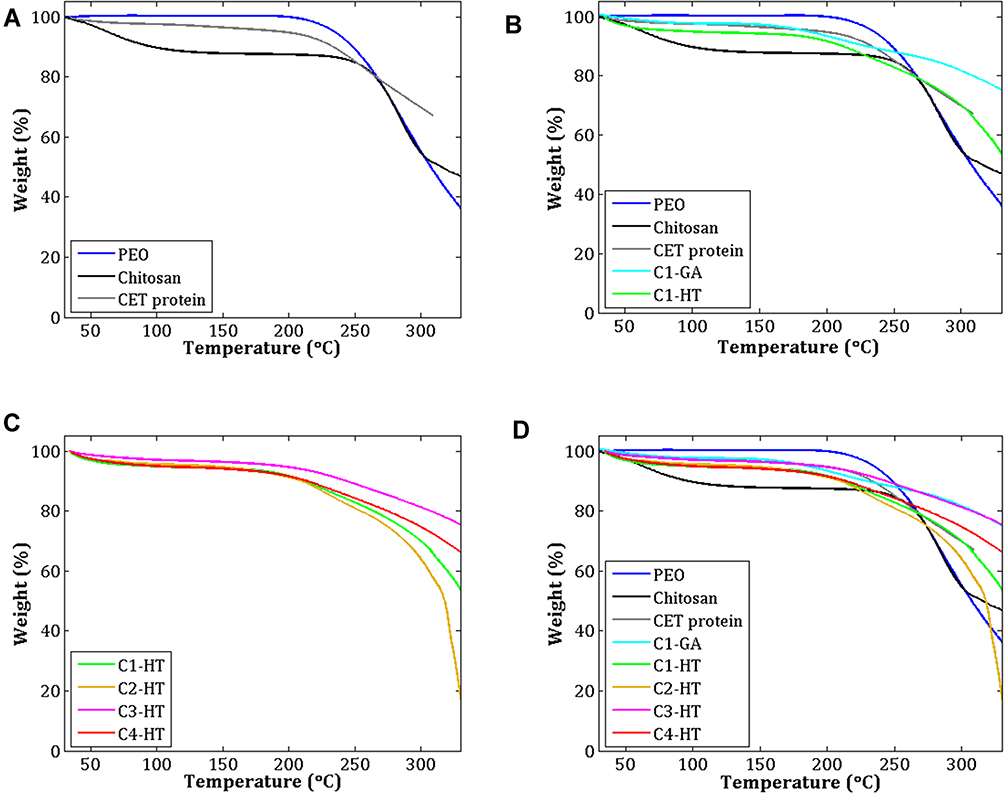 |
Figure 4 TGA curves of (A) PEO, CS, and CET’s protein powder, (B) C1–GA and C1–HT samples, (C) Samples crosslinked by HT, and (D) All samples. Abbreviations: PEO, poly(ethylene oxide); CS, chitosan; CET’s protein, Colocasia esculenta tuber protein; GA, glutaraldehyde; HT, heat treatment; TGA, thermo-gravimetric analysis. |
In the temperature range of 30–350 °C, samples of C1–GA, C1–HT, C2–HT, C3–HT, and C4–HT display three stages of mass change. The TGA curves of the C1–GA, and C1–HT samples exhibited differences in their thermal stability (Figure 4B). The C1–GA sample indicated higher thermal stability compared to the C1–HT sample. Of all the HT crosslinked samples (Figure 4C), differences in the concentration of CS and CET’s protein did not change the TGA profile of the CET’s protein–CS–PEO nanofiber membrane. At temperatures 30–40 °C, the mass loss in C1–GA, C1–HT, C2–HT, C3–HT, and C4–HT samples are around 0.6%, 1.7%, 1.3%, 0.6%, 1.2%, respectively. A comparative thermal analysis of various samples is presented in (Figure 4D). Three thermal stages in the nanofiber membrane can be observed: the first stage, presumably due to loss of moisture and water trapped at around 30–100 °C; the second stage, the mass loss may be related to the decomposition temperature of CS and CET’s protein at around 200–250 °C; the third stage, a mass loss of about 250–350 °C is the same temperature as the thermal degradation of pure PEO. The results of this thermal degradation are like the fiber morphology in which the fiber structure of C1–HT and C2–HT sample is fused, and the average diameter of the fiber cannot be measured.
Mechanical Properties
The tensile stress-strain curves of the non-crosslinked and crosslinked electrospun CET’s protein–CS–PEO nanofibers are plotted in Figure 5. Comparing Figure 5A–C, the tensile stress of the non-crosslinked sample increased gradually until the peak and decreased. Conversely, the tensile stress of the crosslinked sample showed a steep slope. This behavior can be explained that non-crosslinked samples can be easily pulled from one another, resulting in low tensile stress and high strain. The higher the concentration of CET’s protein and CS, the ultimate tensile stress, and ultimate strain decreased, while Young’s modulus increased. These findings revealed that biomaterials based on protein generally have lower mechanical properties; besides that, CS has a semi-rigid chain and brittle.36,37 However, it cannot be pulled freely for the crosslinked sample due to the presence of inter-fiber bonds. Based on the tensile stress-strain curves,38 the material properties in C1 and C2; C3 and C4; C1–GA, C2–GA, and C4–GA; C3–GA, C3–HT, and C4–HT samples tend to be soft and tough, soft and weak, hard and brittle, and hard and strong, respectively.
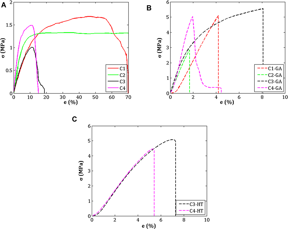 |
Figure 5 Stress–strain curves of CET’s protein–CS–PEO nanofiber membrane (A) Before crosslinking, (B) After GA vapor crosslinking, and (C) After HT crosslinking. Abbreviations: σ, ultimate tensile strength; e, ultimate strain; GA, glutaraldehyde; HT, heat treatment; CET’s protein, Colocasia esculenta tuber protein; CS, chitosan; PEO, poly(ethylene oxide). |
The effect of crosslinking on the mechanical properties of the nanofiber membrane is shown in Table 2. GA vapor and HT crosslinking generated the nanofiber membrane more rigid, because there is an increase in ultimate tensile stress and Young’s modulus, with a decrease in ultimate strain. The trend of ultimate tensile stress, ultimate strain, and Young’s modulus from the combination of CET’s protein and CS concentrations in non-crosslinked samples and GA vapor crosslinking samples are presented in Figure 6. The higher concentration of CET’s protein and CS in GA vapor and HT crosslinking gave an increasing trend in Young’s modulus compared to non-crosslinked samples. The modulus Young in each of the C1–GA, C2–GA, C3–GA, C4–GA samples was 13.7; 6.5; 9.9; 7.8-fold higher than of the C1, C2, C3, C4 samples. The modulus Young of the C3–HT and C4–HT samples were 6.1 and 2.7-fold higher than of the C3 and C4 samples. According to Yao et al,39 the high Young’s modulus can be attributed to the smaller average diameter of the nanofiber membrane. The GA vapor crosslinking provided ultimate tensile stress, and Young’s modulus was higher than the HT crosslinking. This result can be attributed to stronger covalent bonds in GA vapor crosslinking than non-covalent bonds in HT crosslinking. Therefore, GA often has the most significant effect on mechanical properties compared to other crosslinking because GA crosslinking occurs through various mechanisms.40 Although the samples demonstrate different behavior in crosslinking, these results are compatible within the range of mechanical properties (Young’s modulus) of the human skin of 15–150 MPa.41
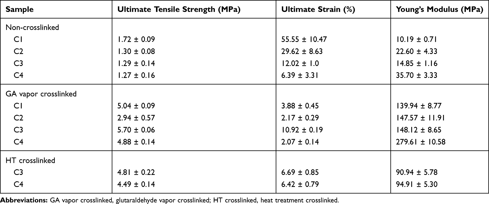 |
Table 2 Mechanical Properties of Electrospun CET’s Protein–CS–PEO Nanofibers Before and After GA Vapor and HT Crosslinking |
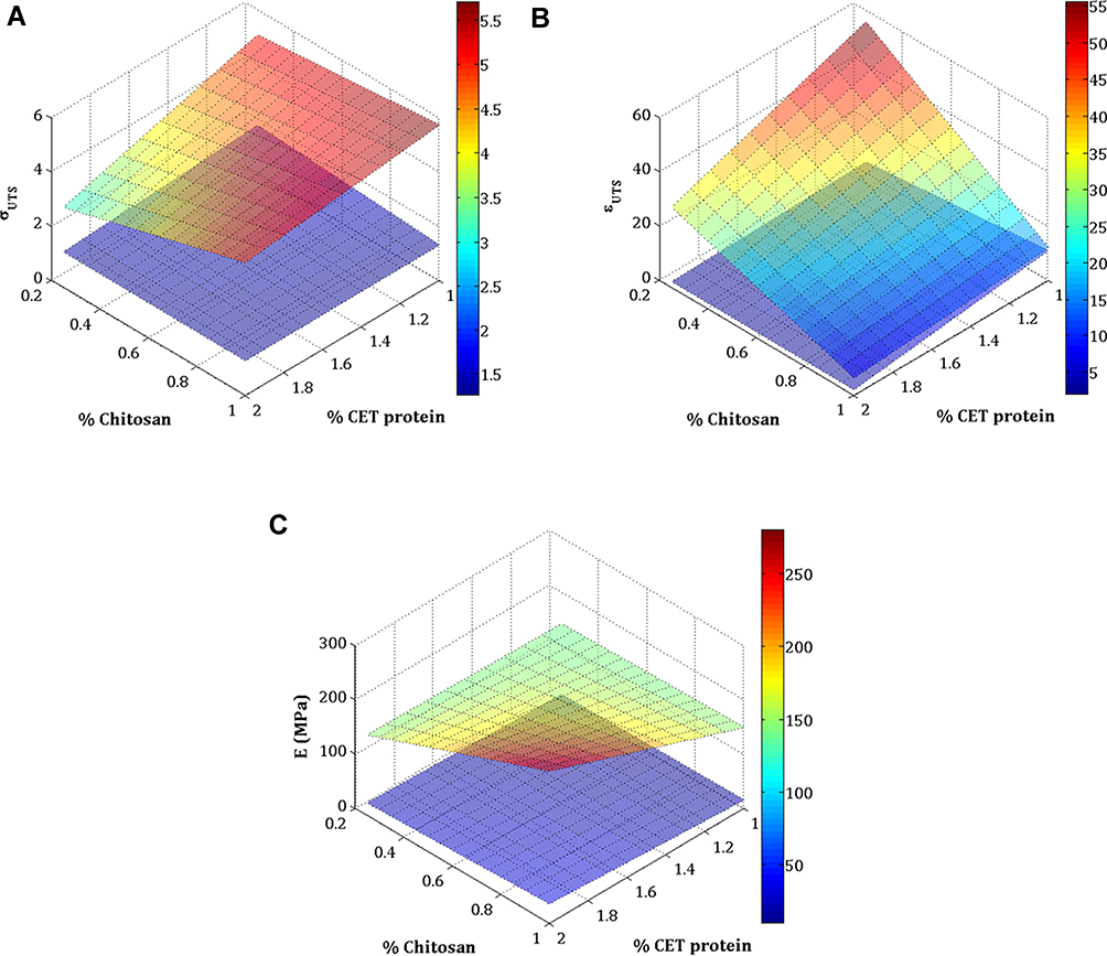 |
Figure 6 Surface plot relationship of CET’s protein and CS concentration in before and after GA vapor crosslinking sample of the: (A) Ultimate tensile stress, (B) Ultimate tensile strain, and (C) Young’s modulus. Abbreviations: σ, ultimate tensile strength; ϵ, ultimate strain; E, Young’s modulus; CET’s protein, Colocasia esculenta tuber protein; CS, chitosan, GA, glutaraldehyde. |
In vitro Degradation
The biodegradation of the crosslinked electrospun nanofibers was examined using PBS solution by monitoring their weight loss, as shown in Figure 7A. From day 1 to day 7, the highest weight loss was in the C2–GA sample, while the lowest weight loss was in the C3–GA sample. The HT crosslinked samples (C3–HT and C4–HT) demonstrated higher weight loss rates than GA vapor crosslinked samples (C3–GA, and C4–GA). The trend of degradation rate on seven days of the combination of CET’s protein and CS concentrations in GA vapor crosslinking samples is presented in Figure 7B. The degradation rate of the sample increased with the increase in CET’s protein concentration and the decrease in CS concentration. This finding is related because the types of proteins used in this study are water-soluble proteins. The crosslinking method is also considered important in terms of reducing the weight of the nanofiber membrane. GA vapor crosslinking provided stronger crosslinking than HT crosslinking because the polymer chains are bound to each other through covalent bonds.36 After 72 h, CET’s protein–CS–PEO nanofiber membrane exhibited a degradation profile of 25–45%. The nanofiber membrane matrix is expected to be replaced by collagen synthesized by fibroblast cells in the body.1,42
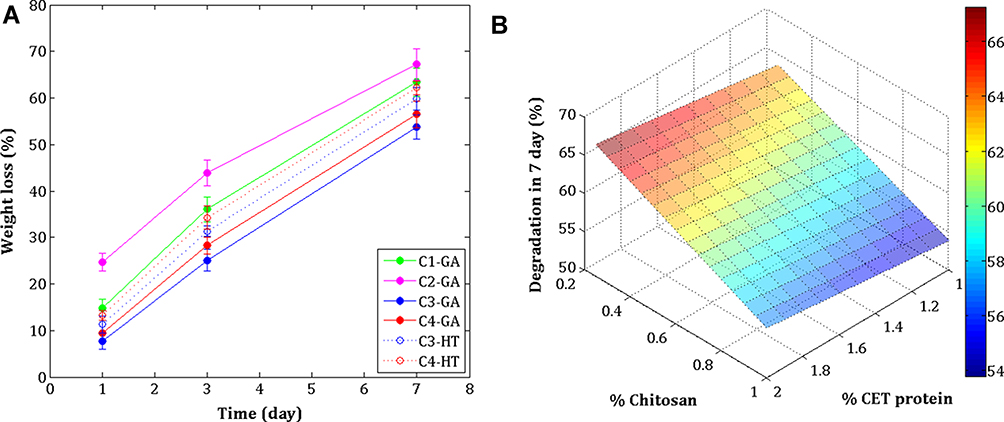 |
Figure 7 In vitro degradation of the crosslinked electrospun (A), and surface plot relationship of CET’s protein and CS concentration in degradation rate for 7 days (B). Abbreviations: GA, glutaraldehyde; HT, heat treatment; CET’s protein, Colocasia esculenta tuber protein; CS, chitosan. |
The SEM images confirmed that non-crosslinked electrospun nanofibers completely lost their fiber architecture in contact with PBS (Figure S2). GA vapor and HT crosslinking presented complete structural stability after soaking in PBS (Figure 8). By day 1, the fiber structure swelled rapidly and expanded in the C2–GA sample, whereas in the other samples, the fiber structure became more compact. The pores between fibers in the C1–GA sample shrunk, and the film quickly formed in the C2–GA sample on day 3. In contrast, the C3–GA, C4–GA, C3–HT, and C4–HT fiber structures were still clearly visible after three days. By day 7, there were few fibers areas in C4–GA, and C4–HT samples. Some areas in the C1–GA, and C2–GA becoming film-like. The C3–GA, and C3–HT samples maintained their structure until seven days. The C3–GA, and C3–HT fibers membranes display optimal preservation of fiber morphology, followed by C4–GA, and C4–HT; C1–GA; and then C2–GA, respectively. These findings suggest that HT crosslinking can be a reliable method to improve the structural stability of CET’s protein–CS–PEO nanofiber membrane in aqueous media.
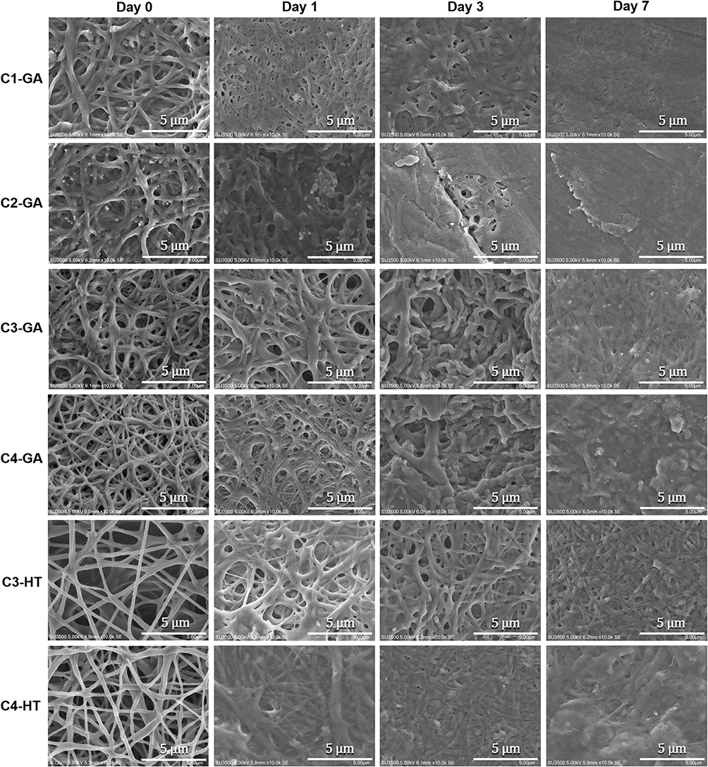 |
Figure 8 Scanning electron microscope images of CET’s protein–CS–PEO crosslinked fiber morphology after soaking in PBS for 1, 3, and 7 days. Abbreviations: GA, glutaraldehyde; HT, heat treatment; CET’s protein, Colocasia esculenta tuber protein; CS, chitosan; PEO, poly(ethylene oxide); PBS, phosphate buffered saline. |
Antibacterial Activity of Crosslinked CET’s Protein–CS–PEO Nanofibers
Antibacterial properties of CET’s protein–CS–PEO crosslinked nanofibers were examined on both Gram-positive S. aureus and Gram-negative E. coli. Table 3 presents each bacterial reduction (R) of various samples. The antibacterial activity of CS on nanofiber membranes has been demonstrated before.37,43-46 At zero contact time, there is a decrease in the number of colonies of Gram-positive and Gram-negative bacteria (Figure S3). The antibacterial activities observed with all samples at zero contact time are significantly higher than the control. After 1 hour of contact, the bacterial reduction rate showed more than 98% in S. aureus and 90–95% in E. coli bacteria. These results suggested that the bacterial reduction rate in S. aureus is significantly higher compared to E. coli. It is well known that although S. aureus has a thicker layer of peptidoglycan on its cell walls, S. aureus is more susceptible to chemicals than E. coli because its cell walls are not as complex as E. coli.18 Also, S. aureus has impermeable lipids on the outer membrane of bacteria.47 Moreover, the reduction rate of the bacterial colony showed that it was less than 99.9% of the total CFU/mL, then it is defined as a bacteriostatic activity.48 The reduction in bacterial colonies proved that the content of CS as an antibacterial agent could act in the nanofiber membrane. The mechanism of the antibacterial activity of CS is based on the electrostatic interaction between the polycationic structure (positive charge) carried by the CS chain and the anionic component (negative charge), which is dominant in the bacterial cell wall. This interaction disrupts the normal function of bacterial cell membranes, causes loss of membrane permeability, intracellular leakage, and ultimately cell death.18 As a result, nanofiber membranes containing 0.25% (w/v) CS concentration can provide a reduction in the growth of S. aureus and E. coli bacteria. After the CS concentration was increased to 1% (w/v), the reduction of bacteria on the nanofiber membrane was not significantly different. The absence of this difference is due to the concentration of CS solution inhibiting the growth of E. coli bacteria at a minimum of 0.025% (w/v), whereas S. aureus bacteria of at least 0.05% (w/v).18 Besides, the antibacterial activity increased slightly with increasing CET’s protein concentration, but the increase in antibacterial activity was not significantly different between samples. Although the rate reduction of bacterial showed no significant difference between CS and CET’s protein concentrations, both GA vapor and HT crosslinking methods used did not damage the CS and CET’s protein components in the nanofiber membrane.
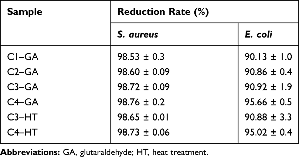 |
Table 3 The Bacterial Reduction Rate (R) of the Different Crosslinked Nanofibers |
Cytocompatibility of Crosslinked CET’s Protein–CS–PEO Nanofibers
The nanofiber membrane’s surface matrix can provide favorable conditions for cell adhesion and proliferation due to similarities in physical properties and tissue structure.49 The PrestoBlue test for cell proliferation in the nanofiber membrane of various ratios was studied, and the results are shown in Figure 9. The proliferation rate of BJ cells was significantly different on days 1, 3, 5, and 7. The C1–GA, C2–GA, C3– GA, C4–GA, C3–HT, and C4–HT samples presented that the cell proliferation increased significantly compared to the control sample on days 1, 3, 5, and 7. The results showed that BJ cells were metabolically active on nanofiber membranes containing CET’s protein and CS, and all nanofiber membranes indicated no signs of cytotoxicity in cells.
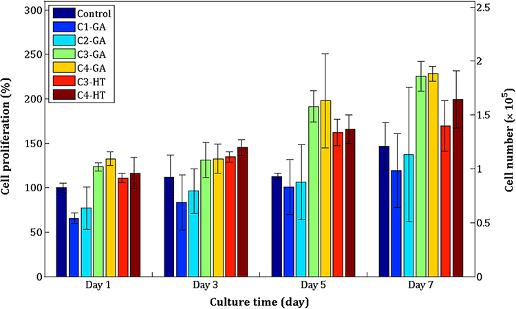 |
Figure 9 BJ cell proliferation on crosslinked electrospun C1–GA, C2–GA, C3–GA, C4–GA, C3–HT, and C4–HT nanofibers. Abbreviations: GA, glutaraldehyde; HT, heat treatment. |
On day 1 and day 5, the highest cell proliferation significantly among all test samples was the C4–GA sample. C4–HT sample had significantly higher BJ cell proliferation on the 3 days compared to C1–GA, C2–GA, C3–HT, and control samples. On the 7 days of cell culture, BJ cell proliferation in C4–GA samples was found to be significantly higher than cell proliferation in C1–GA, C2–GA, C3–HT, C4–HT, and control samples. In this study, the presence of CET’s protein in the nanofiber membrane is expected to stimulate cell attachment, leading to enhanced proliferation of BJ cells. The most substantial amino acid composition of the CET’s protein is arginine.16 Fujiwara et al reported that arginine amino acid can increase the proliferation rate of NIH-3T3 and HDF cells.50 The amino acids glycine and proline also exist in the CET’s protein.16 It is known that glycine and proline are the main protein components of the connective tissue that compose collagen.7,51 The increased concentration of CET’s protein in the nanofiber membrane gave a significant increase to BJ cell proliferation on day 1 for C2–GA, C4–GA, C4–HT samples, then on day 3 and day 7 for C4–HT samples. This result is by previous studies that the CET’s protein increases the growth of fibroblast cells after 24 h incubation.16 BJ cell proliferation increased significantly with increasing CS concentration in the C3–GA and C4–GA samples on days 1 through 7. Gomes et al52 and Chen et al27 reported that CS could produce a more positive charge for cell adhesion. These results indicated that CET’s protein and CS have good compatibility with BJ cells.
The comparison of crosslinking methods to cell proliferation on the 7 days showed that GA vapor crosslinked samples performed significantly higher BJ cell proliferation than HT crosslinked samples. The process of cell adhesion on the substrate is influenced by the size of the fiber diameter,53 the surface structure of the substrate, and the presence of proteins on the substrate.54 The C4–HT and C3–HT samples have a higher degradation rate than the C4–GA and C3–GA samples. The structure of nanofiber membranes that are more easily degraded causes BJ cells not to adhere totally to the nanofiber membrane so that the growth of BJ cells cannot increase significantly.
Cell Morphology
Cell morphology on various CET’s protein–CS–PEO nanofiber membrane was studied by SEM on days 3 and 5, and the results are shown in Figure 10. BJ cells attach and spread on the surface of the nanofiber membrane. On the 3 days, the spread of BJ cells on C4–GA and C3–GA samples was higher than C1–GA, C2–GA, C3–HT, and C4–HT samples. After 5 days of cell culture, cells begin to cover almost all the surface area of the nanofiber membrane. SEM micrographs (Figure 10M) showed that cells on the surface of the nanofiber membrane grow toward the orientation of the fiber structure. In this study, the CET’s protein–CS–PEO nanofiber membrane positively provided a three-dimensional structure for the attachment and growth of BJ cells. The cells not only show good adhesion but also proliferate well in fiber. Therefore, the combination of antibacterial activity and cytocompatibility makes the CET’s protein–CS–PEO nanofiber membrane as a great candidate for wound dressing application.
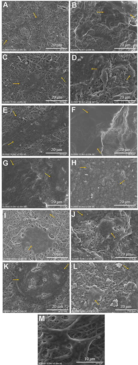 |
Figure 10 Scanning electron microscope images of BJ cell on crosslinked electrospun C1–GA (A, B), C2–GA (C, D), C3–GA (E, F), C4–GA (G, H), C3–HT (I, J), C4–HT (K, L) after (3, 5) days of cell proliferation and a higher magnification of BJ cell’s morphology on C4–GA (M). Note: Yellow arrow shows the area covered by BJ cells. |
Conclusion
In the present study, two different crosslinking methods were investigated to provide structural integrity of the membranes in contact with aqueous media. SEM images revealed that the crosslinked electrospun CET’s protein–CS–PEO nanofibers have suitable fiber diameters range for ideal wound dressing. Mechanical properties exhibited that the crosslinked electrospun nanofibers are compatible with human skin, which has Young’s modulus of 15–150 MPa. Crosslinked electrospun nanofibers by GA vapor and HT also proved improvement in degradation behavior. In the antibacterial assessment, both crosslinking methods GA vapor and HT exhibited > 90% antibacterial activities against both Gram-positive S. aureus and Gram-negative E. coli bacteria. The evaluation of cell proliferation assay and cell morphology revealed that the crosslinked electrospun CET’s protein–CS–PEO nanofibers could facilitate human skin fibroblast cells to attach and proliferate. Cell proliferation increased with the increase of CET’s protein concentration. Cell proliferation in GA vapor crosslinked samples (C3–GA and C4–GA) was significantly higher compared to HT crosslinked samples (C3–HT and C4–HT). Our results suggest that, of the two crosslinking methods, GA vapor crosslinked nanofibers are the great suited for wound dressing applications. However, HT crosslinking can be a simple method of choice without the need for chemical compounds during the crosslinking process. Our study not only present insights on the design of crosslinked electrospun CET’s protein–CS–PEO nanofibers, but also introduce other bioactive materials from plant-derived proteins for the potential use of the wound dressing materials.
Acknowledgments
This work was supported by Indonesia Endowment Fund for Education (Lembaga Pengelola Dana Pendidikan - LPDP), Ministry of Finance Republic of Indonesia. K. Khairurrijal acknowledges financial support by Ministry of Research and Technology Republic of Indonesia under PTUPT Research Grant.
Disclosure
The authors report no conflicts of interest in this work.
References
1. Beanes SR, Dang C, Soo C, Ting K. Skin repair and scar formation: the central role of TGF-β. Expert Rev Mol Med. 2003;5(8):1–22. doi:10.1017/S1462399403005817
2. Zahedi P, Rezaeian I, Ranaei‐Siadat SO, Jafari SH, Supaphol P. A review on wound dressings with an emphasis on electrospun nanofibrous polymeric bandages. Polym Adv Technol. 2010;21(2):77–95. doi:10.1002/pat.1625
3. Wild T, Rahbarnia A, Kellner M, Sobotka L, Eberlein T. Basics in nutrition and wound healing. Nutrition. 2010;26(9):862–866. doi:10.1016/j.nut.2010.05.008
4. Pilehvar-Soltanahmadi Y, Dadashpour M, Mohajeri A, Fattahi A, Sheervalilou R, Zarghami N. An overview on application of natural substances incorporated with electrospun nanofibrous scaffolds to development of innovative wound dressings. Mini Rev Med Chem. 2018;18(5):414–427. doi:10.2174/1389557517666170308112147
5. Abrigo M, McArthur SL, Kingshott P. Electrospun nanofibers as dressings for chronic wound care: advances, challenges, and future prospects. Macromol Biosci. 2014;14(6):772–792. doi:10.1002/mabi.201300561
6. Stechmiller JK. Understanding the role of nutrition and wound healing. Nutr Clin Pract. 2010;25(1):61–68. doi:10.1177/0884533609358997
7. Guo S, DiPietro LA. Factors affecting wound healing. J Dent Res. 2010;89(3):219–229. doi:10.1177/0022034509359125
8. Brown KL, Phillips TJ. Nutrition and wound healing. Clin Dermatol. 2010;28(4):432–439. doi:10.1016/j.clindermatol.2010.03.028
9. Lim TK. Edible Medicinal and Non-Medicinal Plants. Vol. 1. Springer; 2012.
10. Kaushal P, Kumar V, Sharma H. Utilization of taro (Colocasia esculenta): a review. J Food Sci Technol. 2015;52(1):27–40. doi:10.1007/s13197-013-0933-y
11. Pereira PR, Del Aguila EM, Verícimo MA, Zingali RB, Paschoalin VMF, Silva JT. Purification and characterization of the lectin from taro (Colocasia esculenta) and its effect on mouse splenocyte proliferation in vitro and in vivo. Protein J. 2014;33(1):92–99. doi:10.1007/s10930-013-9541-y
12. Pereira PR, Winter HC, Verícimo MA, et al. Structural analysis and binding properties of isoforms of tarin, the GNA-related lectin from Colocasia esculenta. Biochim Biophys Acta. 2015;1854(1):20–30. doi:10.1016/j.bbapap.2014.10.013
13. Pereira PR, Silva JT, Verícimo MA, Paschoalin VM, Teixeira GA. Crude extract from taro (Colocasia esculenta) as a natural source of bioactive proteins able to stimulate haematopoietic cells in two murine models. J Funct Foods. 2015;18:333–343. doi:10.1016/j.jff.2015.07.014
14. Pereira PR, Corrêa ACNTF, Vericimo MA, Paschoalin VMF. Tarin, a potential immunomodulator and COX‐inhibitor lectin found in taro (Colocasia esculenta). Compr Rev Food Sci Food Saf. 2018;17(4):878–891. doi:10.1111/1541-4337.12358
15. Corręa AC, Vericimo MA, Dashevskiy A, Pereira PR, Paschoalin VM. Liposomal taro lectin nanocapsules control human glioblastoma and mammary adenocarcinoma cell proliferation. Molecules. 2019;24(3):471. doi:10.3390/molecules24030471
16. Wardhani RAK, Asri LA, Rachmawati H, Khairurrijal R, Purwasasmita BS. Stabilization of chitosan-polyethylene oxide electrospun nanofibrous containing Colocasia esculenta tuber protein. Mater Res Express. 2019. doi:10.1088/2053-1591/ab5087
17. MacKay DJ, Miller AL. Nutritional support for wound healing. Altern Med Rev. 2003;8(4).
18. Kong M, Chen XG, Xing K, Park HJ. Antimicrobial properties of chitosan and mode of action: a state of the art review. Int J Food Microbiol. 2010;144(1):51–63. doi:10.1016/j.ijfoodmicro.2010.09.012
19. Sridhar R, Lakshminarayanan R, Madhaiyan K, Barathi VA, Lim KHC, Ramakrishna S. Electrosprayed nanoparticles and electrospun nanofibers based on natural materials: applications in tissue regeneration, drug delivery and pharmaceuticals. Chem Soc Rev. 2015;44(3):790–814. doi:10.1039/C4CS00226A
20. Pakravan M, Heuzey M-C, Ajji A. A fundamental study of chitosan/PEO electrospinning. Polymer. 2011;52(21):4813–4824. doi:10.1016/j.polymer.2011.08.034
21. Huang Z-M, Zhang Y-Z, Kotaki M, Ramakrishna S. A review on polymer nanofibers by electrospinning and their applications in nanocomposites. Compos Sci Technol. 2003;63(15):2223–2253. doi:10.1016/S0266-3538(03)00178-7
22. Zhang Y, Su B, Venugopal J, Ramakrishna S, Lim C. Biomimetic and bioactive nanofibrous scaffolds from electrospun composite nanofibers. Int J Nanomedicine. 2007;2(4):623.
23. Sill TJ, von Recum HA. Electrospinning: applications in drug delivery and tissue engineering. Biomaterials. 2008;29(13):1989–2006. doi:10.1016/j.biomaterials.2008.01.011
24. Iqbal H, Khan BA, Khan ZU, et al. Fabrication, physical characterizations and in vitro antibacterial activity of cefadroxil-loaded chitosan/poly (vinyl alcohol) nanofibers against Staphylococcus aureus clinical isolates. Int J Biol Macromol. 2020;144:921–931. doi:10.1016/j.ijbiomac.2019.09.169
25. Reddy N, Reddy R, Jiang Q. Crosslinking biopolymers for biomedical applications. Trends Biotechnol. 2015;33(6):362–369. doi:10.1016/j.tibtech.2015.03.008
26. Chen J-P, Chang G-Y, Chen J-K. Electrospun collagen/chitosan nanofibrous membrane as wound dressing. Colloids Surf a Physicochem Eng Asp. 2008;313:183–188. doi:10.1016/j.colsurfa.2007.04.129
27. Chen L, Zhu C, Fan D, et al. A human‐like collagen/chitosan electrospun nanofibrous scaffold from aqueous solution: electrospun mechanism and biocompatibility. J Biomed Mater Res A. 2011;99(3):395–409. doi:10.1002/jbm.a.33202
28. Çay A, Miraftab M, Kumbasar EPA. Characterization and swelling performance of physically stabilized electrospun poly (vinyl alcohol)/chitosan nanofibres. Eur Polym J. 2014;61:253–262. doi:10.1016/j.eurpolymj.2014.10.017
29. Grkovic M, Stojanovic DB, Pavlovic VB, Rajilic-Stojanovic M, Bjelovic M, Uskokovic PS. Improvement of mechanical properties and antibacterial activity of crosslinked electrospun chitosan/poly (ethylene oxide) nanofibers. Compos B Eng. 2017;121:58–67. doi:10.1016/j.compositesb.2017.03.024
30. Wardhani RAK, Asri L, Nasir M, Purwasasmita BS. Preparation of chitosan-polyethylene oxide-Colocasia esculenta flour nanofibers using electrospinning method. J Mech Eng Sci Technol. 2019;3(1):1–7. doi:10.17977/um016v3i12019p001
31. Bradford MM. A rapid and sensitive method for the quantitation of microgram quantities of protein utilizing the principle of protein-dye binding. Anal Biochem. 1976;72(1–2):248–254. doi:10.1016/0003-2697(76)90527-3
32. Laemmli UK. Cleavage of structural proteins during the assembly of the head of bacteriophage T4. Nature. 1970;227(5259):680. doi:10.1038/227680a0
33. Ramakrishna S. An Introduction to Electrospinning and Nanofibers. World Scientific; 2005.
34. Bizarria M, d’Ávila M, Mei L. Non-woven nanofiber chitosan/PEO membranes obtained by electrospinning. Braz J Chem Eng. 2014;31(1):57–68. doi:10.1590/S0104-66322014000100007
35. Hassiba AJ, El Zowalaty ME, Webster TJ, et al. Synthesis, characterization, and antimicrobial properties of novel double layer nanocomposite electrospun fibers for wound dressing applications. Int J Nanomedicine. 2017;12:2205. doi:10.2147/IJN.S123417
36. Reddy N, Yang Y. Potential of plant proteins for medical applications. Trends Biotechnol. 2011;29(10):490–498. doi:10.1016/j.tibtech.2011.05.003
37. Kohsari I, Shariatinia Z, Pourmortazavi SM. Antibacterial electrospun chitosan–polyethylene oxide nanocomposite mats containing bioactive silver nanoparticles. Carbohydr Polym. 2016;140:287–298. doi:10.1016/j.carbpol.2015.12.075
38. Lampman S. Characterization and Failure Analysis of Plastics. Asm International; 2003.
39. Yao J, Bastiaansen CW, Peijs T. High strength and high modulus electrospun nanofibers. Fibers. 2014;2(2):158–186. doi:10.3390/fib2020158
40. Martinez AW, Caves JM, Ravi S, Li W, Chaikof EL. Effects of crosslinking on the mechanical properties, drug release and cytocompatibility of protein polymers. Acta Biomater. 2014;10(1):26–33. doi:10.1016/j.actbio.2013.08.029
41. Annaidh AN, Bruyère K, Destrade M, Gilchrist MD, Otténio M. Characterization of the anisotropic mechanical properties of excised human skin. J Mech Behav Biomed Mater. 2012;5(1):139–148. doi:10.1016/j.jmbbm.2011.08.016
42. Gurtner GC, Werner S, Barrandon Y, Longaker MT. Wound repair and regeneration. Nature. 2008;453(7193):314. doi:10.1038/nature07039
43. Arkoun M, Daigle F, Heuzey M-C, Ajji A. Mechanism of action of electrospun chitosan-based nanofibers against meat spoilage and pathogenic bacteria. Molecules. 2017;22(4):585. doi:10.3390/molecules22040585
44. Ardila N, Medina N, Arkoun M, Heuzey M-C, Ajji A, Panchal CJ. Chitosan–bacterial nanocellulose nanofibrous structures for potential wound dressing applications. Cellulose. 2016;23(5):3089–3104. doi:10.1007/s10570-016-1022-y
45. Erdem R, Akalın M. Characterization and evaluation of antimicrobial properties of electrospun chitosan/polyethylene oxide based nanofibrous scaffolds (with/without nanosilver). J Ind Text. 2015;44(4):553–571. doi:10.1177/1528083713503000
46. Doğan G, Özyıldız F, Başal G, Uzel A. Fabrication of electrospun chitosan and chitosan/poly (ethylene oxide) nanofiber webs and assessment of their antimicrobial activity. Int Polym Process. 2013;28(2):143–150. doi:10.3139/217.2604
47. Gupta RS. Protein phylogenies and signature sequences: a reappraisal of evolutionary relationships among archaebacteria, eubacteria, and eukaryotes. Microbiol Mol Biol Rev. 1998;62(4):1435–1491. doi:10.1128/MMBR.62.4.1435-1491.1998
48. Silva F, Lourenço O, Queiroz JA, Domingues FC. Bacteriostatic versus bactericidal activity of ciprofloxacin in Escherichia coli assessed by flow cytometry using a novel far-red dye. J Antibiot (Tokyo). 2011;64(4):321. doi:10.1038/ja.2011.5
49. Kim JI, Hwang TI, Aguilar LE, Park CH, Kim CS. A controlled design of aligned and random nanofibers for 3D bi-functionalized nerve conduits fabricated via a novel electrospinning set-up. Sci Rep. 2016;6:23761. doi:10.1038/srep23761
50. Fujiwara T, Kanazawa S, Ichibori R, et al. L-arginine stimulates fibroblast proliferation through the GPRC6A-ERK1/2 and PI3K/Akt pathway. PLoS One. 2014;9(3):e92168. doi:10.1371/journal.pone.0092168
51. Friess W. Collagen–biomaterial for drug delivery. Eur J Pharm Biopharm. 1998;45(2):113–136. doi:10.1016/S0939-6411(98)00017-4
52. Gomes SR, Rodrigues G, Martins GG, et al. In vitro and in vivo evaluation of electrospun nanofibers of PCL, chitosan and gelatin: a comparative study. Mater Sci Eng C. 2015;46:348–358. doi:10.1016/j.msec.2014.10.051
53. Lowery JL, Datta N, Rutledge GC. Effect of fiber diameter, pore size and seeding method on growth of human dermal fibroblasts in electrospun poly (ɛ-caprolactone) fibrous mats. Biomaterials. 2010;31(3):491–504. doi:10.1016/j.biomaterials.2009.09.072
54. Wilson CJ, Clegg RE, Leavesley DI, Pearcy MJ. Mediation of biomaterial–cell interactions by adsorbed proteins: a review. Tissue Eng. 2005;11(1–2):1–18. doi:10.1089/ten.2005.11.1
 © 2020 The Author(s). This work is published and licensed by Dove Medical Press Limited. The full terms of this license are available at https://www.dovepress.com/terms.php and incorporate the Creative Commons Attribution - Non Commercial (unported, v3.0) License.
By accessing the work you hereby accept the Terms. Non-commercial uses of the work are permitted without any further permission from Dove Medical Press Limited, provided the work is properly attributed. For permission for commercial use of this work, please see paragraphs 4.2 and 5 of our Terms.
© 2020 The Author(s). This work is published and licensed by Dove Medical Press Limited. The full terms of this license are available at https://www.dovepress.com/terms.php and incorporate the Creative Commons Attribution - Non Commercial (unported, v3.0) License.
By accessing the work you hereby accept the Terms. Non-commercial uses of the work are permitted without any further permission from Dove Medical Press Limited, provided the work is properly attributed. For permission for commercial use of this work, please see paragraphs 4.2 and 5 of our Terms.