")
Back to Journals » International Journal of Nanomedicine » Volume 14
Osteochondral repair using scaffolds with gradient pore sizes constructed with silk fibroin, chitosan, and nano-hydroxyapatite
Authors Xiao H, Huang W, Xiong K, Ruan S, Yuan C, Mo G, Tian R, Zhou S, She R, Ye P, Liu B, Deng J
Received 20 October 2018
Accepted for publication 12 February 2019
Published 22 March 2019 Volume 2019:14 Pages 2011—2027
DOI https://doi.org/10.2147/IJN.S191627
Checked for plagiarism Yes
Review by Single anonymous peer review
Peer reviewer comments 2
Editor who approved publication: Dr Mian Wang
Hongli Xiao,1,* Wenliang Huang,1,* Kun Xiong,1 Shiqiang Ruan,1 Cheng Yuan,1 Gang Mo,1 Renyuan Tian,1 Sirui Zhou,1 Rongfeng She,2 Peng Ye,3 Bin Liu,4 Jiang Deng1
1Department of Orthopedics, Third Affiliated Hospital of Zunyi Medical University, Zunyi 563000, Guizhou Province, People’s Republic of China; 2Department of Orthopedics, Guizhou Province People’s Hospital, Guiyang 550002, Guizhou Province, People’s Republic of China; 3Emergency and Trauma Ward, Affiliated Hospital of Zunyi Medical University, Zunyi 563000, Guizhou Province, People’s Republic of China; 4Surgical Laboratory, Zunyi Medical University, Zunyi 563000, Guizhou Province, People’s Republic of China
*These authors contributed equally to this work
Background: One of the main problems associated with the development of osteochondral reparative materials is that the accurate imitation of the structure of the natural osteochondral tissue and fabrication of a suitable scaffold material for osteochondral repair are difficult. The long-term outcomes of single- or bilayered scaffolds are often unsatisfactory because of the absence of a progressive osteochondral structure. Therefore, only scaffolds with gradient pore sizes are suitable for osteochondral repair to achieve better proliferation and differentiation of the stem cells into osteochondral tissues to complete the repair of defects.
Methods: A silk fibroin (SF) solution, chitosan (CS) solution, and nano-hydroxyapatite (nHA) suspension were mixed at the same weight fraction to obtain osteochondral scaffolds with gradient pore diameters by centrifugation, freeze-drying, and chemical cross-linking.
Results: The scaffolds prepared in this study are confirmed to have a progressive structure starting from the cartilage layer to bone layer, similar to that of the normal osteochondral tissues. The prepared scaffolds are cylindrical in shape and have high internal porosity. The structure consists of regular and highly interconnected pores with a progressively increasing pore distribution as well as a progressively changing pore diameter. The scaffold strongly absorbs water, and has a suitable degradation rate, sufficient space for cell growth and proliferation, and good resistance to compression. Thus, the scaffold can provide sufficient nutrients and space for cell growth, proliferation, and migration. Further, bone marrow mesenchymal stem cells seeded onto the scaffold closely attach to the scaffold and stably grow and proliferate, indicating that the scaffold has good biocompatibility with no cytotoxicity.
Conclusion: In brief, the physical properties and biocompatibility of our scaffolds fully comply with the requirements of scaffold materials required for osteochondral tissue engineering, and they are expected to become a new type of scaffolds with gradient pore sizes for osteochondral repair.
Keywords: tissue engineering, bone marrow mesenchymal stem cells, bioscaffolds, osteochondral defect
Introduction
Sports-related injuries, accidental injuries, and congenital diseases result in various inevitable osteoarticular injuries. Osteochondral defects often occur in osteoarticular injuries involving smooth cartilage and subchondral bone. Because of the limited self-healing ability of osteochondral tissues, especially the large-area osteochondral defects, the injured bone and joint tend to undergo chronic degeneration. Therefore, surgical intervention is often necessary for intra-articular osteochondral defects, and the treatment plan depends on various factors such as the age, diameter, and depth of the lesion.1 Autologous osteochondral transplantation is currently recognized as the clinical gold standard for the treatment of osteochondral defects. However, this technique has many inherent limitations, such as the requirement of a high surgical technique, complicated operating procedures, shortage of graft source, less quantity of grafts, poor matching of graft and host cartilage congruency, sequelae of the graft donor site, incomplete graft–host integration, and degeneration of the transplanted graft.1,2 Therefore, osteochondral tissue engineering has attracted increasing attention. A variety of factors including the scaffold materials, stem cells, and signal factors have been studied for osteochondral repair3 to develop appropriate strategies for the regeneration of damaged cartilage and subchondral bone tissues.
One of the main difficulties in the development of osteochondral biomaterials is to accurately imitate the structure of the natural osteochondral tissue. As previously reported, a scaffold with a single pore diameter has been implanted as a support material in the area of an osteochondral defect. Unfortunately, the long-term results are often unsatisfactory because of a lack of progressive osteochondral structure starting from the cartilage layer to bone layer in the regenerated tissues. This impedes normal metabolism and biomechanical support of the articular cartilage, and causes cell degeneration in the central region of the defect, eventually leading to fragmentation and collapse of the articular cartilage.4,5 Therefore, the new concept of constructing bilayered scaffolds for osteochondral tissue engineering has emerged for repairing osteochondral defects. Some scholars have separately constructed cartilage scaffolds and bone scaffolds and then integrated these two kinds of scaffolds using stitches,6,7 a bio-sealant, or a bio-glue.8–10 There is consequently a clear interface between the bone layer and cartilage layer, and the cells cannot penetrate the interface to form a calcified cartilage, resulting in an unstable bone–cartilage interface. New bone tissues are likely to grow into the cartilage area of the osteochondral defect11 or long-term stratification may appear. With the advancement in the bilayered scaffold research, some inherent flaws in the osteochondral repair have become more obvious; it has come to light that a distinct boundary formed between the cartilage layer and bone layer causes uneven differentiation of the stem cells in the cartilage–bone junction area or produces a distinct band zone,12,13 eventually leading to the failure of bone and cartilage integration. Owing to the particularity of the bone and cartilage structures, only an appropriate osteochondral scaffold can facilitate the proliferation and differentiation of the seed cells into osteochondral tissue in vivo, and thereby complete the osteochondral repair.
Numerous studies have shown that silk fibroin (SF), chitosan (CS), and nano-hydroxyapatite (nHA) have no cytotoxic side-effects and have no special odor. All three materials have good biological and physicochemical properties, and they can be used as good scaffold materials. In our previous study, we confirmed that bone scaffolds based on SF-CS14 and SF-CS-nHA composites15 with a single pore diameter were successfully prepared by vacuum freeze-drying and chemical cross-linking methods, the SF/CS scaffolds produced with a ratio of 1:1 of SF solution and CS solution, and SF-CS-nHA scaffolds produced with a ratio of 1:1:1 of SF solution, CS solution, and nHA suspension showed the best performance. After extensive investigations, SF-CS and SF-CS-nHA scaffolds were confirmed to have good histocompatibility with no cytotoxicity,16,17 and they could better repair rabbit knee articular cartilage defects14 and large-segmental radial bone defects.18,19 Herein, inspired by the successful results of SF-CS-nHA scaffolds with a single pore diameter in the reparation of cartilage and bone defects, we combined the freeze-drying method with a centrifugation method to fabricate SF-CS-nHA scaffolds with gradient pore diameter. The physical and biological properties of the scaffolds were evaluated to select a biomimetic composite scaffold that shows optimal performance in the repair of osteochondral defects.
Materials and methods
A series of experiments were carried out in the early stage to prepare osteochondral scaffolds with gradient pore diameters by varying different parameters including the optimal ratio of the scaffold raw materials, freezing method, methods to develop pores, and the cross-linking. The finalized optimal scheme is shown in Figure 1.
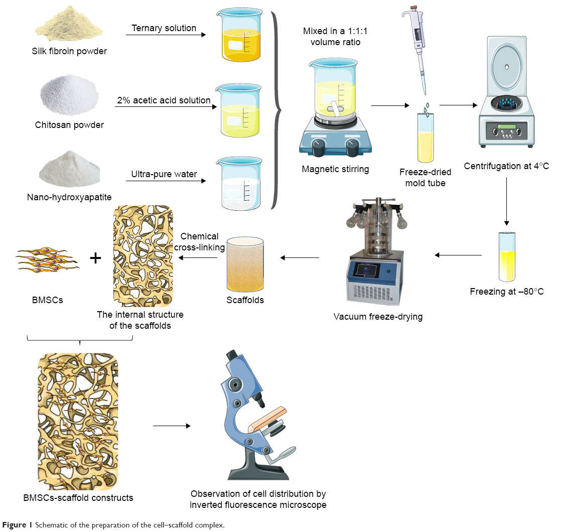 | Figure 1 Schematic of the preparation of the cell–scaffold complex. |
Preparation of scaffolds
First, a series of solutions of SF and CS, and suspensions of nHA were prepared at three different concentrations, as follows:
SF solution
SF (1 g) (Huzhou Xintiansi Biotechnology Co., Ltd., Zhejiang, China) was immersed in a ternary mixture (10 mL) consisting of CaCl2 (MACKLIN, Shanghai, China), H2O (Ultrapure Water Preparation System, EMD Millipore, Billerica, MA, USA), and ethanol (Tianjin Kemiou Chemical Reagent Co., Ltd., Tianjin, China) at a molar ratio of 1:8:2, and stirred at 80°C using a C-MAG HS4 magnetic heating stirrer (300 r/min; IKA, Staufen, Germany) for 1 hour. After the dissolution of SF, the solution was transferred to a dialysis bag with a molecular weight cutoff of 3500 D (Biosharp, Anhui, China), dialyzed for 2 days against tap water and 1 day against deionized water. The effect of dialysis was detected using a 5% Na2CO3 solution. Then, an SF solution was prepared after filtration, 10 mL filtered SF solution were taken, placed in a beaker, dried at 60°C for 72 hours, and then weighed. W1 is the weight of SF solution and beaker after drying, M0 is the weight of the beaker, and V is the volume of SF solution. The mass fraction of SF solution was calculated using the following formula: mass fraction =(M1−M0)/V×100%. The SF solution was thereafter concentrated or diluted to a concentration of 2, 3, or 4%, and stored at 4°C.
CS solution
CS (degree of deacetylation >95%, viscosity =100–200 MPa.s; Aladdin, Shanghai, China) was mixed with 2% acetic acid (purity >99.9%; Aladdin), and magnetically stirred at a speed of 300 r/min at 100°C for 1 hour until its complete dissolution. 10 mL filtered CF solution were taken, placed in a beaker, dried at 60°C for 72 hours, and then weighed. W1 is the weight of CF solution and beaker after drying, M0 is the weight of the beaker, and V is the volume of CF solution. The mass fraction of CF solution was calculated using the following formula: mass fraction =(M1−M0)/V×100%. The prepared CS solutions were concentrated or diluted to concentrations of 2, 3, and 4%, and stored at 4°C until use.
nHA suspension
The nHA (biomedical grade, 98%, <0.2 μm; Aladdin) was mixed in ultrapure water and magnetically stirred at room temperature to obtain suspensions with concentrations of 2, 3, and 4%. The nHA suspension was prepared freshly before use.
Preparation of the scaffold
Three different mixtures with 2, 3, and 4% of each of the constituents were prepared by thoroughly mixing the SF solution, CS solution, and nHA suspension with the same given concentration at a volume ratio of 1:1:1 via magnetic stirring. Then, the mixtures were pipetted out into prepared mold grooves (1.8-mL standable extorsion cryopreservation tubes, Corning Incorporated, Corning, NY, USA) and centrifuged (500 r/min) at 4°C for 5 minutes using a cryogenic centrifuge (centrifuge 5424R, Eppendorf, Hamburg, Germany), and frozen in a refrigerator at −80°C (DW86L630, AUCMA, China) for 24 hours. Then, the frozen scaffolds were quickly taken out and sealed with parafilm (Parafilm, Neenah, WI, USA), pores were made in the sealing film using a 5-mL sterile syringe needle (22G, outer diameter 0.7 mm, inner diameter 0.4 mm, Chengdu Xinjin Shifeng Medical Apparatus & Instrument Co., Ltd, Chengdu, China) for breathability, and for preventing failure, displacement of scaffold components during vacuum freeze-drying. The scaffolds were then shaped into cylinders in a vacuum dryer (Thermo Fisher Scientific, Waltham, MA, USA) for 24 hours and the dried scaffolds were immersed in a solution containing 75% methanol (Tianjin Kemiou Chemical Reagent Co., Ltd.) and 1 mol/L NaOH (≥98.0%; Aladdin) at a volume ratio of 1:1, and allowed to cross-link at 4°C for 24 hours. Subsequently, the scaffolds were ultrasonically cleaned with ultra-pure water in an ultrasonic cleaning instrument (Kunshan Ultrasonic Instruments Co., Ltd., Kunshan, China) three times, for 5 minutes each time, and dried under vacuum for another 24 hours for second shaping. The dried scaffolds were subsequently immersed in a cross-linking agent containing 50 mmol/L of 1-ethyl-(3-dimethylaminopropyl)carbodiimide hydrochloride (EDC, 98%; Aladdin) and 20 mmol/L of N-hydroxysuccinimide (NHS, 98%; Aladdin) and cross-linked at 4°C for 24 hours. The scaffolds were thereafter ultrasonically cleaned (thrice) and vacuum-dried for 24 hours for final shaping. The so-prepared scaffolds were collected, sealed, and stored in a refrigerator at 4°C until use. The process of preparation is shown in Figure 1.
Evaluation of the physical properties of the scaffold
Measurement of the scaffold size
The diameter and height of the scaffold were measured using an accurate digital caliper (accuracy 0.01 mm; Aladdin).
Determination of the porosity of the scaffold
The porosity of the scaffold was determined by a modified liquid displacement method. The scaffold was immersed in a 5-mL measuring barrel containing ethanol for 10 minutes until the air overflowed completely. The volume of ethanol was measured before and after immersion, and recorded as V1 and V2, respectively. The scaffold was then taken out and the volume of residual ethanol was recorded as V3. The porosity is calculated as follows:
|
Determination of the water swelling rate
The scaffold was immersed in double-distilled water for 24 hours and taken out. The excess water on the scaffold surface was sucked off with absorbent gauze and the scaffold was weighed as m1. Then, the scaffold was dried and its weight was measured as m2. The water swelling ratio is calculated as follows: Pwater absorption=(m1−m2)/m2*100%.
Determination of the dissolution rate in hot water
The weight of the scaffold was first measured as m1, and it was immersed in 1× phosphate buffered solution (PBS) and continuously shaken at a constant temperature of 37°C. The scaffold was taken out after 1, 2, 3, 4, and 5 weeks, respectively, followed by ultrasonic cleaning (thrice). Thereafter, the scaffold was dried in vacuum and weighed as m2 using an electronic balance (AS220.R2, RADWAG, Radom, Poland). The dissolution rate in hot water is calculated as follows: Pdissolved=(m1−m2)/m2*100%. Then, the dissolution rate was plotted as a function of time, and linear regression analysis was performed to analyze the dissolution rate of the scaffold in hot water with time.
Mechanical testing
The conventional compressive mechanical properties of the scaffold were tested using an Instron 5969 mechanical testing machine (USA) with a preload force of 0.1 N, a load speed of 0.1 N/min, and a loading rate of 2 mm/min. The stress-strain curve was then plotted to evaluate the mechanical properties of the scaffold.
Determination of the water swelling rate of the scaffolds after compression
According to the 2015 report on Chinese nutrition and chronic disease,20 average weights are 66.2 kg for males and 57.3 kg for females. Therefore, the maximum pressure of 66.2 kg (662 N, 10 N/kg) was chosen, the scaffolds were placed vertically, and an Instron 5969 mechanical testing machine (USA) was used to compress the scaffolds. After compression, the scaffolds were taken out and placed into double-distilled water for 24 hours. The excess water on the scaffold surface was sucked off with absorbent gauze, and the scaffold was weighed as m1. Then, the scaffold was dried and its weight was measured as m2. The water swelling ratio of the scaffolds before and after compression was determined using the following equation: Pcompression=(m1−m2)/m2*100%. The recovery ability of the scaffolds after applying compression was measured.
Internal structure of the scaffold and the pore size
The scaffold was cut straight in the middle, and the longitudinal section was coated with Au using an ion sputtering apparatus (E-1010, HITACHI, Tokyo, Japan). A scanning electron microscope (SEM; S-3400N, HITACHI) was used to observe the pore structure and morphology of the scaffold. The scaffold was divided into four layers from top to bottom, the size of 100 pores per layer was counted using SEM analysis software, and the average pore size of each layer was then calculated.
Determination of the biocompatibility of the scaffold
Culture of rat bone marrow mesenchymal stem cells (BMSCs)
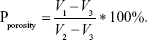
The cryopreserved cells, taken out from liquid nitrogen as reported previously21 (Figure 2), were immediately placed in a constant temperature water bath at 37°C, oscillated, and resuscitated within 1 minute. The mixture was then centrifuged at 1,000 r/min for 5 minutes and the supernatant was discarded. A complete medium [Dulbecco’s Modified Eagle’s Medium/F12 (DMEM/F12; Gibco, Carlsbad, CA, USA)+10% fetal bovine serum (Gibco)+1% streptomycin (HyClone, Logan City, UT, USA)] was used to adjust the cell concentration to 1×10⁵/mL, and the cells were inoculated in a 25-cm2 angled neck cell culture flask with a vent cap (Corning) placed in a 5% CO2 incubator (MCO-18AC, Panasonic, Osaka, Japan) at 37°C. The medium was changed every 2 days. When the cells covered 80% of the bottom of the cell culture flask, the cells were digested with 0.25% trypsin (HyClone). Subsequently, the cell concentration was adjusted to 1×10⁵ cell/mL, and the cells were then seeded in a cell culture flask (5 mL/flask), and culture was continued.
 | Figure 2 Morphology of passage 3 bone marrow mesenchymal stem cells (A, 40×; B, 100×; C, 200×). |
Construction and in vitro culture of BMSC-scaffold complex
According to the physical properties, an appropriate scaffold was selected as a cell carrier. The prepared scaffolds were sterilized with ethylene oxide, pre-treated with sterile 1×PBS, and placed in 24-well culture plates (Corning). Rat BMSCs were inoculated onto the scaffold at a density of 5×10⁴. Rat BMSCs were uniformly seeded at a density of 5×10⁴/scaffold into each layer (L1–L4) of the scaffolds with a pipette (Eppendorf). After 2 hours of culture, a complete medium was added and the BMSC-scaffold complex was placed in the 5% CO2 constant temperature incubator at 37°C. The complete medium was replaced every day.
Cell proliferation in the BMSC-scaffold complex
The BMSC-scaffold complex was taken out after 1, 3, 5, 7, 9, and 11 days of culture and was equally stratified into four layers from top to bottom under aseptic conditions. The layers were transferred into a 96-well plate (Corning) and the cell proliferation in each layer of the BMSC-scaffold complex was evaluated using cell counting kit-8 (CCK-8; Biosharp Biotechnology Co., Ltd., Anhui, China). The complete medium (200 μL) and CCK-8 solution (20 μL) were added into the plate and the complex was incubated at 37°C, in the 5% CO2 constant-temperature incubator for 3 hours and fully shaken with a microplate fast oscillator (QB-9002; Qilinbeier Instrument Manufacturing Co., Ltd., Jiangsu, China). The supernatant (110 μL) was transferred to a fresh 96-well plate and the optical density (OD) of each well was measured at the wavelength of 450 nm using a continuous wavelength plate reader (Synergy HTX, Bio Tek, Winooski, VT, USA) and the cell proliferation curve per layer was plotted.
Cell distribution in the BMSC-scaffold complex
The cell distribution in the BMSC-scaffold complex was observed by nuclear fluorescence staining and SEM. According to the results of the CCK-8 test, the BMSC-scaffold complex prepared over the most optimal time was selected and fixed at room temperature in a 4% paraformaldehyde solution (Biosharp Biotechnology Co., Ltd.) for 30 minutes. The complex was then longitudinally cut into 1–2 mm-thick sections, then the sections were rinsed thrice with 1×PBS, dyed with 4,6-diamidino-2-phenylindole (DAPI, 10 μg/mL, Soleil Biotech Co. Ltd., Beijing, China) for 10 minutes, and photographed using an inverted fluorescence microscope (IX53, Olympus Corporation, Tokyo, Japan) to observe the stratified distribution of the cells in the BMSC-scaffold complex (there were four layers from top to bottom). The sections were rinsed thrice with ultrapure water, transferred to a 2 mL EP tube, and frozen in a −80°C refrigerator for 24 hours. The frozen BMSCs-scaffold complex was then vacuum-dried for another 24 hours and cut longitudinally. The longitudinal sections were coated with Au using the ion sputtering apparatus. The cell morphology and distribution in each layer of BMSCs-scaffold complex were observed by SEM.
Statistical analysis
The data were analyzed using SPSS18.0 and are expressed as mean±standard deviation (SD). Comparison between different groups was performed using t-test, and multi-group comparison was carried out using one-way analysis of variance. A value of P<0.05 is considered significant.
Results
Global observation of the scaffold
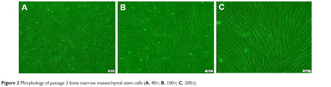
As shown in Figure 3, the white scaffold is approximately cylindrical with a regular shape. It is extremely light, has no special odor, and has obvious pressure resistance and elasticity. As shown in Figure 4 and Table 1, the heights of scaffolds prepared using 2, 3, and 4% solutions of its constituents (hereafter referred to as Scaffold-1, Scaffold-2, and Scaffold-3, respectively) were found to be 9.20±0.26, 9.55±0.35, and 9.53±0.23 mm, respectively, with no significant differences among the groups (F=1.964, P=0.198, n=4). Further, the average diameters of Scaffold-1, Scaffold-2, and Scaffold-3 were estimated to be 5.86±0.50 mm, 6.53±0.07 mm, and 6.40±0.32 mm, respectively; once again, there are no significant differences among the groups (F=4.200, P=0.051, n=4). However, the mean weights of Scaffold-1, Scaffold-2, and Scaffold-3 were found to be 6.21±0.27, 10.29±0.65, and 13.80±0.66 mg, respectively, with the differences among the groups being statistically significant (F=371.673, P=0.000, n=4). These results reveal that only the weight of the scaffold changed over a certain proportion, with no significant changes in the scaffold size, indicating that the scaffold was shaped well.
 | Figure 3 Appearance of the silk fibroin/chitosan/nano-hydroxyapatite scaffolds: Scaffold-1 (A), Scaffold-2 (B), and Scaffold-3 (C). |
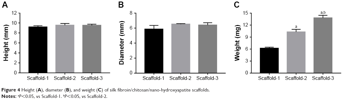 | Figure 4 Height (A), diameter (B), and weight (C) of silk fibroin/chitosan/nano-hydroxyapatite scaffolds. |
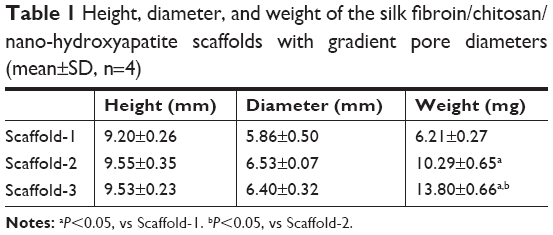 | Table 1 Height, diameter, and weight of the silk fibroin/chitosan/nano-hydroxyapatite scaffolds with gradient pore diameters (mean±SD, n=4) |
Porosity of the scaffold
As shown in Figure 5A and Table 2, the porosities of Scaffold-1, Scaffold-2, and Scaffold-3 were determined to be 91.30±3.35, 89.50±3.11, and 82.58%±1.47%, respectively. Whereas the porosities of Scaffold-1 and Scaffold-2 (P=0.452, n=4) are not significantly different, the porosity of Scaffold-3 decreased significantly (F=12.154, P4-2=0.001, P4-3=0.004, n=4) in comparison. This indicates that the three kinds of scaffolds are highly porous and the porosity decreases with increasing concentrations of the scaffold.
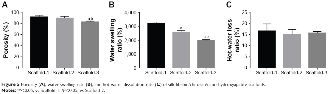 | Figure 5 Porosity (A), water swelling rate (B), and hot-water dissolution rate (C) of silk fibroin/chitosan/nano-hydroxyapatite scaffolds. |
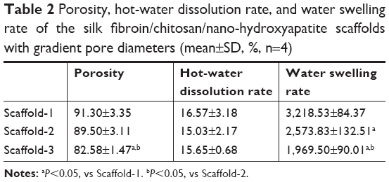 | Table 2 Porosity, hot-water dissolution rate, and water swelling rate of the silk fibroin/chitosan/nano-hydroxyapatite scaffolds with gradient pore diameters (mean±SD, %, n=4) |
Water swelling rate of the scaffold
As shown in Figure 5B and Table 2, the water swelling rates of Scaffold-1, Scaffold-2, and Scaffold-3 are 3,218.53±84.37, 2,573.83±132.51, and 1,969.50%±90.01%, respectively, with the intergroup differences being statistically significant (F=142.829, P=0.000, n=4). This indicates that the three kinds of scaffolds strongly absorb water, and the water swelling rate decreases with increasing concentrations of the scaffold.
Dissolution rate of the scaffold in hot water
As shown in Figure 5C and Table 2, the hot-water dissolution rate of Scaffold-1, Scaffold-2, and Scaffold-3 oscillated at 37°C for 5 continuous weeks is 16.57±3.18, 15.03±2.17, and 15.65%±0.68%, respectively, with no significant difference between the groups (F=0.425, P=0.668, n=4). The hot-water dissolution rate was then plotted as a function of time; the trend of the hot-water dissolution rate shows no significant difference among different groups (Figure 6). After the first week, the dissolution rate was faster, and tended to be stable from the second to fifth weeks, which might be related to the loss of nHA during the rinsing of the scaffold after the first week. These findings suggest that the degradability of the scaffold is good, and the hot-water dissolution rate of the scaffold is less affected by the material concentration in the range of 2%–4%. Moreover, the hot-water dissolution rate shows a linear relationship with the dissolution time (Figure 7). Linear regression analysis reveals that the correlation coefficients of the hot-water dissolution rate and the dissolution time of each group are R2%=0.995, R3%=0.970, and R4%=0.980, indicating that there is a high correlation between the hot-water dissolution rate and the dissolution time. The adjusted R2 values of Scaffold-1, Scaffold-2, and Scaffold-3 are 0.990, 0.921, and 0.947, respectively, indicating that the dissolution time could be used to predict the hot-water dissolution rate of the scaffold in a certain range. All the P-values are less than 0.05, indicating a statistically significant regression relationship between the hot-water dissolution rate and the dissolution time. Therefore, the one-way regression equations relating the hot-water dissolution rate and the dissolution time of the scaffold are, Y2%=1.367X2%+9.979, Y3%=1.509X3%+8.067, and Y4%=1.222X4%+9.739 (unit: %). When Y=100%, X2%=65.85, X3%=60.92, X4%=73.86, that is, the three scaffolds can be completely dissolved in vitro within 65.85, 60.92, and 73.86 weeks, respectively.
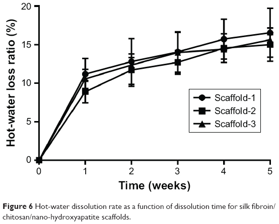 | Figure 6 Hot-water dissolution rate as a function of dissolution time for silk fibroin/chitosan/nano-hydroxyapatite scaffolds. |
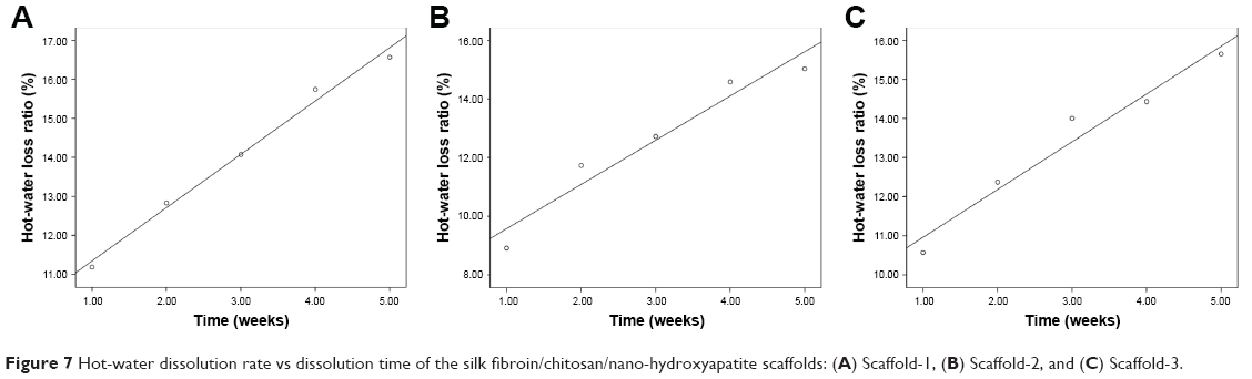 | Figure 7 Hot-water dissolution rate vs dissolution time of the silk fibroin/chitosan/nano-hydroxyapatite scaffolds: (A) Scaffold-1, (B) Scaffold-2, and (C) Scaffold-3. |
Mechanical properties
The stress–strain curves of the scaffold shown in Figures 8A–D indicate that the stress gradually increases with the gradual increase in strain, and the compressive performance of the scaffold increases remarkably with an increase in the material concentration. As shown in Figure 8E, the elastic moduli of Scaffold-1, Scaffold-2, and Scaffold-3 were 0.0955, 0.1762, and 0.3468 MPa, respectively. In addition, when the strain reaches 0.80, the compressive stresses of Scaffold-1, Scaffold-2, and Scaffold-3 are 0.12, 0.26, and 0.53 MPa, respectively. These findings indicate that the scaffold has good compression resistance and can withstand certain external pressures.
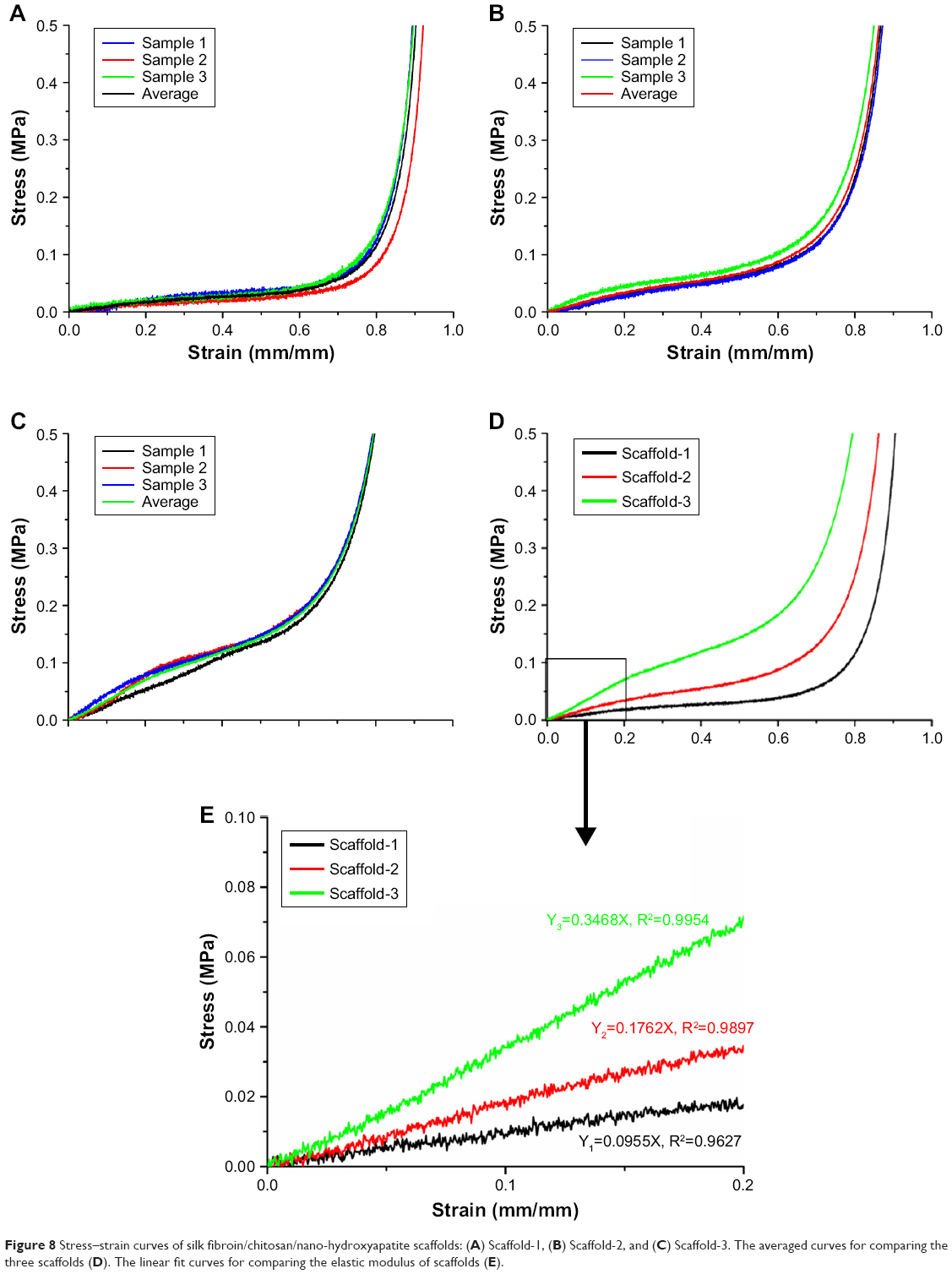 | Figure 8 Stress–strain curves of silk fibroin/chitosan/nano-hydroxyapatite scaffolds: (A) Scaffold-1, (B) Scaffold-2, and (C) Scaffold-3. The averaged curves for comparing the three scaffolds (D). The linear fit curves for comparing the elastic modulus of scaffolds (E). |
Water swelling rate of the scaffolds after compression
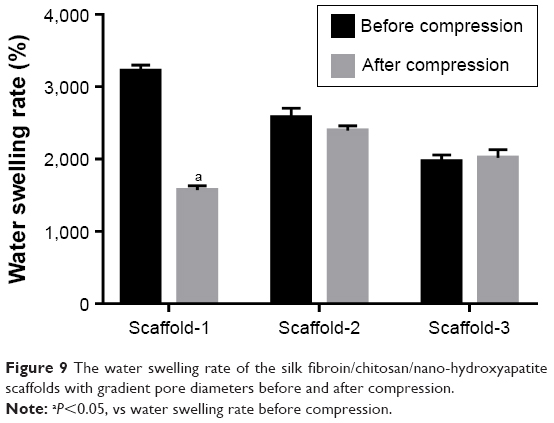
As shown in Figure 9 and Table 3, the water swelling rates of Scaffold-1, Scaffold-2, and Scaffold-3 after compression are 1,587.27±63.09, 2,379.53±77.04, and 1,989.53%±118.90%, respectively. Compared with the water swelling rate of Scaffold-1 before compression, the water swelling rate was significantly reduced after compression. No significant change in the water swelling rates of the Scaffold-2 and Scaffold-3 groups was found before and after compression. This indicates that the three kinds of scaffolds have excellent water absorption capacity. After an external force equal to the average weight of Chinese adults was applied, Scaffold-2 and Scaffold-3 had good recovery from compression. Scaffold-1 may have poor compression resistance and mechanical stability due to its low material concentration, which causes irreversible changes in the structure of Scaffold-1 after compression.
 | Figure 9 The water swelling rate of the silk fibroin/chitosan/nano-hydroxyapatite scaffolds with gradient pore diameters before and after compression. |
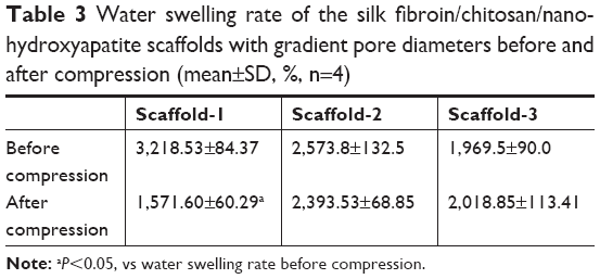 | Table 3 Water swelling rate of the silk fibroin/chitosan/nano-hydroxyapatite scaffolds with gradient pore diameters before and after compression (mean±SD, %, n=4) |
Internal structure of the scaffold and pore size
The SEM images show a honeycomb-like internal structure of the scaffold, with polygonal and circular pores and highly inter-connected gaps (Figure 10). The pores are densely distributed from the upper part to the lower part of the scaffold, and the pore diameter gradually decreases from the upper part to the lower part of the scaffold. The nHA content increased gradually from the upper part to the lower part of the scaffold. The inner wall of the scaffold gradually thickened with an increase in the material content corresponding to Scaffold-1, Scaffold-2, and Scaffold-3, respectively. As shown in Figure 11 and Table 4, the pore size of each scaffold shows a different degree of decrease from layer 1 (L1) to layer 4 (L4) (F2%=22.973, P=0.000; F3%=11.709, P=0.001; F4%=20.151, P=0.016; n=4). Scaffold-2 shows a uniform pore distribution, and the pore size from top to bottom changed slightly, followed by Scaffold-1, and Scaffold-3 shows uneven pore distribution, an obviously changed pore size, and fewer pores. In addition, the pore size of the scaffolds corresponding to the same layer showed no significant differences from L1 to L4 (FL1=1.458, P=0.283; FL2=0.027, P=0.973; FL3=0.598, P=0.570; FL4=1.780, P=0.223; n=4); this may be associated with the differences in pore size and uneven pore distribution throughout the three scaffolds. These findings indicate that, within the material concentration of 2%–4% in the precursor solutions, a progressive change in the pore size and local accumulation of nHA may occur in the resulting scaffold, owing to the centrifugal force.
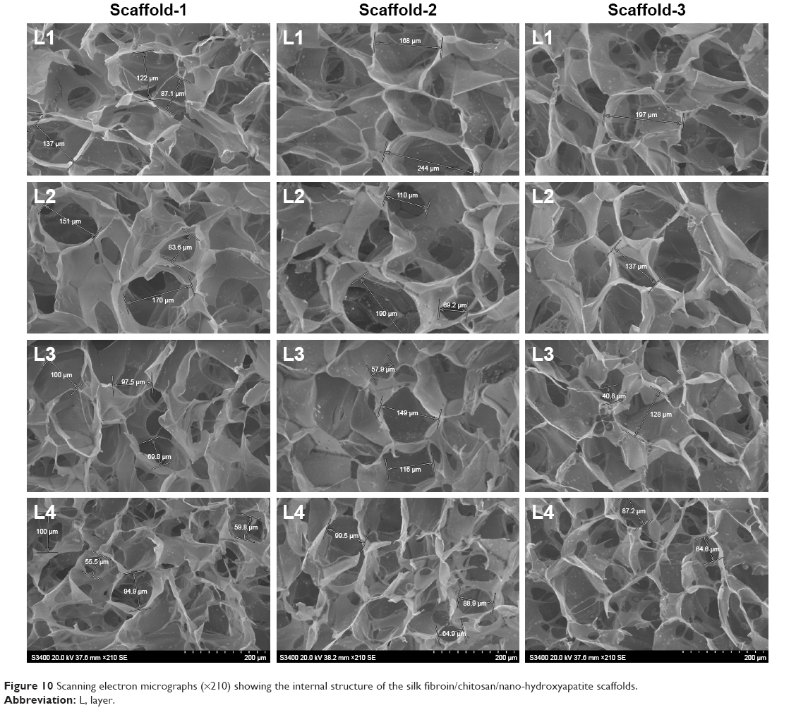 | Figure 10 Scanning electron micrographs (×210) showing the internal structure of the silk fibroin/chitosan/nano-hydroxyapatite scaffolds. |
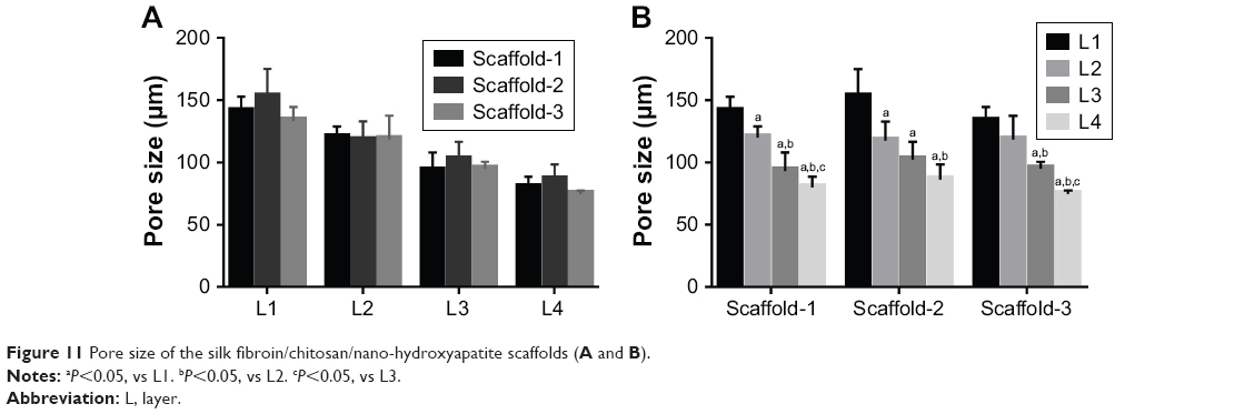 | Figure 11 Pore size of the silk fibroin/chitosan/nano-hydroxyapatite scaffolds (A and B). |
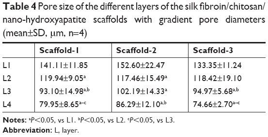 | Table 4 Pore size of the different layers of the silk fibroin/chitosan/nano-hydroxyapatite scaffolds with gradient pore diameters (mean±SD, μm, n=4) |
Cell proliferation in the BMSC-scaffold complex
As shown in Figure 12 and Table 5, the cells in each layer of the BMSC-scaffold complex began to proliferate logarithmically after 3 days of culture, and then they proliferated at a stable rate after 9 days of culture. After 1 and 3 days of culture, there was no significant difference in the cell proliferation between the layers (F1d=1.168, P=0.363; F3d=0.407, P=0.751; n=4). After 5, 7, 9, and 11 days of culture, significant differences were observed in the cell proliferation among the different layers of the complex (F5d=12.432, P=0.001; F7d=4.474, P=0.025; F9d=13.250, P=0.000; F11d=17.830, P=0.000; n=4). These findings reveal that BMSCs can grow normally in the scaffold, there was no obvious slowing of cell proliferation and decreased cell activity. The BMSCs proliferated well in the scaffold with time, implying that the scaffolds have good biocompatibility. Moreover, the cell proliferation was slightly faster in the upper part of the scaffold than in the lower part, which might have resulted from the growth environment. Remarkably, the rate of cell proliferation was not inhibited in any of the layer.
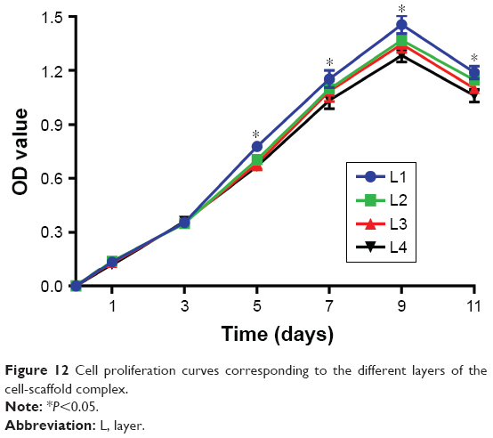 | Figure 12 Cell proliferation curves corresponding to the different layers of the cell-scaffold complex. |
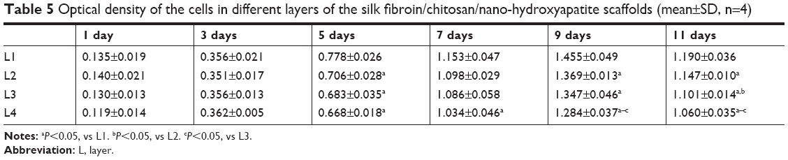 | Table 5 Optical density of the cells in different layers of the silk fibroin/chitosan/nano-hydroxyapatite scaffolds (mean±SD, n=4) |
Cell distribution in the BMSC-scaffold complex
The number of cells in the BMSC-scaffold complex was highest after 9 days of culture, during which the scaffold was assessed for cell distribution. As shown in Figure 13, the cells in the different layers of the scaffold were evenly distributed with uniform morphology of the nucleus, and without metachromatic nuclei, indicating that there were no obvious apoptosis and mutation of stem cells. Moreover, the cell density in the scaffolds from layer 1 to layer 4 decreased slightly. Unfortunately, quantitative analysis could not be performed because of the fluorescence background. These experimental findings reveal that BMSCs can be stably attached to the scaffold and grow well, indicating that the scaffold has good biocompatibility. In addition, more cells were found distributed in the upper layers with larger pores, indicating that the pore size or growing space might have a certain impact on the cell growth and proliferation. As shown in Figure 14, a large amount of cells were adherent to the inner wall of each layer of the scaffold, and the cells were uniform in shape and closely arranged in a long spindle shape. There was no obvious cell disruption or morphological abnormality, indicating that the scaffold has good biocompatibility and no cytotoxicity, and cannot cause apoptosis, malformation, mutation, and rupture of the cells. Under the SME, more cells were also found distributed in the upper layers with larger pores, consistent with the DAPI fluorescence staining findings.
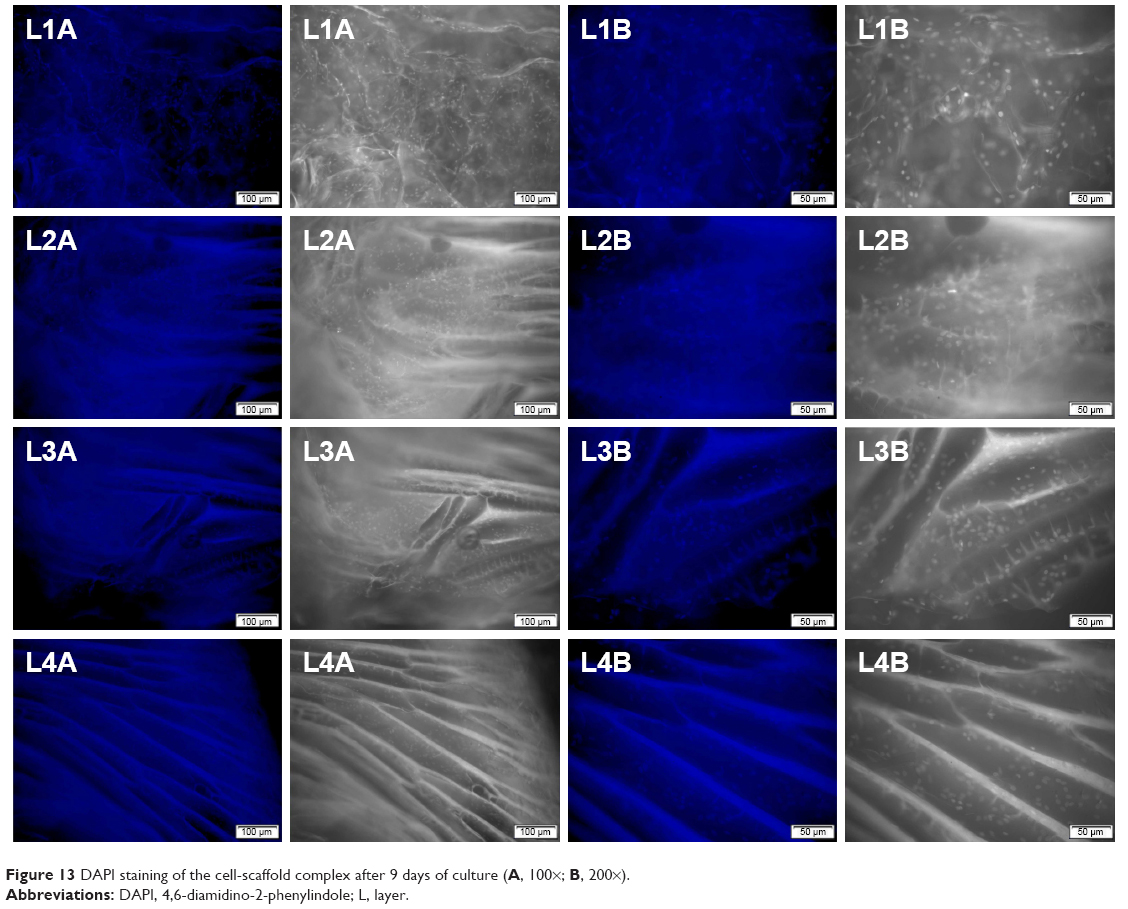 | Figure 13 DAPI staining of the cell-scaffold complex after 9 days of culture (A, 100×; B, 200×). |
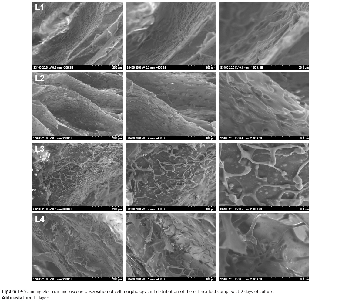 | Figure 14 Scanning electron microscope observation of cell morphology and distribution of the cell-scaffold complex at 9 days of culture. |
Discussion
Current research on osteochondral repair materials has led to great results. Seed cells and scaffold materials are two focal points of current research, and scaffold materials with good performance can provide stable growth and differentiation space for the seed cells.22,23 However, there is no widely accepted ideal osteochondral scaffold material to date, especially for large-area osteochondral defects. The main prevalent issues are the safety, biomechanical properties, degradability, porosity, and histocompatibility of the scaffold materials as well as the influence of the degradation products on the surrounding tissues. Moreover, it is especially important to ensure consistency between the structure of the scaffold material and the normal osteochondral tissue,24 and further extensive investigations are still required on this aspect.
SF is a natural material consisting of three proteins extracted from silk. In its structure, a heavy chain with a relative molecular mass of 350–390 kDa is linked to a light chain with a relative molecular weight of ~26 kDa through a disulfide bond. The third small glycoprotein with a relative molecular mass of ~30 kDa is referred to as P25 protein; it binds by non-covalent hydrophobic interaction.25,26 SF can be easily chemically modified, and it has bactericidal activity, thermal stability, and controllable degradability. Moreover, SF can provide enough strength, toughness, elasticity, and environmental stability when applied to artificial ligaments, cartilage, bone, and nerve tissues.27–29 CS is a derivative formed by the deacetylation of chitin using chemical or deacetylase inhibitors. It is a natural, high-molecular-weight polysaccharide mainly composed of β-(1,4)-N-acetyl-D-glucose and partially repeated β-(1,4)-D-glucosamine,30 and it has a structure similar to that of the cartilage matrix, glycosaminoglycan. Glucosamine monomer, the degradation product of CS, has good mechanical properties, better biocompatibility, and low immunogenicity, which can enhance bone regeneration together with other materials, such as nHA.31 Furthermore, CS also has antibacterial, anti-oxidant, and anti-tumor activities and has been widely used in biomedicine.32–34 nHA is a bioactive ceramic with the chemical formula, [Ca5(OH)(PO4)3]x, that has a similar density to that of human teeth and bones. As an inorganic mineral, nHA has a typical apatite crystal structure and has similar inorganic components as the bone. nHA with good biocompatibility is beneficial for bone conduction, bone tissue growth, and pro-osteogenic differentiation of stem cells,35 which is considered an ideal material for repairing bone defects.36 nHA has been used in various ways, such as a coating material for enhancing the biocompatibility of simple materials37,38 and synthetic hydroxyapatite bone cement, a material for compensating bone loss in orthopedic surgery.39 However, there are some shortcomings in scaffolds made of simple SF, CS, or nHA. The SF scaffold is fragile, with poor osteoinductivity, and has weak water absorption. The CS scaffold is less easily absorbed, with slow degradation, and poor cell adhesion. The simply synthesized nHA materials have low strength and low porosity after molding; however, some research findings reveal that composite materials consisting of nHA are promising for applications in mechanics and biology.36,40–42 Therefore, the three materials, SF, CS, and nHA, can complement one another to satisfy the requirements of tissue-engineered scaffolds. In this study, SF, CS, and nHA were blended at a certain ratio, and the mixture was processed to obtain the SF/CS/nHA composite scaffolds, which not only compensates for their respective shortcomings, but could be prepared controllably to achieve desired properties.
Scaffolds that have highly interconnected pores with porosity greater than 70% are considered to provide good space for cell survival and channels for nutrient transport to maintain cell growth.43 The porosity of all the scaffolds prepared in this study is above 80%. Although there is no consensus on the optimal pore size of a porous cell scaffold for cell growth and mass transfer, in general, the scaffold should have a pore size of 100–300 μm43,44 to facilitate cell growth and reproduction. The average pore size of the three kinds of scaffolds with gradient pore sizes prepared in this study is above 100 μm. The pores were densely distributed from the top to bottom layers, and the pore size gradually decreased from top to bottom. Scaffold-2, which had evenly distributed pores with a smooth gradient, yielded better results (Table 4). In the early days, some scholars used single- or double-layered scaffolds to repair osteochondral defects. However, the lack of a gradient structure led to the collapse or stratification of the repair area, eventually resulting in the failure of repair. The progressive gradient scaffold fabricated in this study provides a good support via the densely distributed pores in the lower layer (bone layer) of the scaffold, which can prevent the collapse of the upper layer (cartilage layer) of the scaffold. This scaffold with gradient pore diameters can enable better transition and integration between the cartilage layer and bone layer. Moreover, SEM images show that the nHA content in the scaffold gradually increases from top to bottom, which can further strengthen the mechanical strength of the lower part of the scaffold. With the advantages of osteogenic induction and bone growth promotion, nHA at a higher concentration in the lower part of the scaffold can induce and promote osteogenesis, while nHA at a lower concentration in the upper part of the scaffold exerts little effects on the cartilage formation. Moreover, owing to the gradient change in the concentration of nHA in the upper and lower parts of the scaffold, the cartilage layer and the bone layer can well transition and integrate. Therefore, the scaffolds prepared in this study not only have suitable porosity and pore size, but also have progressively varying pores and nHA concentration, which can strengthen the supporting capacity of the lower part of the scaffold, while facilitating the formation of bone tissues in the lower part of the scaffold as well as the transition and integration between the cartilage and bone layers of the scaffold.
The chemical cross-linking under the action of light, heat, high-energy radiation, mechanical force, ultrasonic wave, or cross-linking agents enables the formation of a network or a bulk structure between the linear or branched polymers. Therefore, this method can improve the material tension and stability.45,46 Methanol-mediated cross-linking can transform the water-soluble α-helical structure or disc-like structure of SF into a stable β-sheet structure, rendering it water-insoluble. When SF is mixed with CS, active amino groups in the CS can form hydrogen bonds not only with the carboxyl groups in CS, but also with the carboxyl groups in SF, further making the composite scaffold more stable.47,48 EDC and NHS, as two non-toxic and biocompatible cross-linking agents, can promote the cross-linking of SF and CS via the formation of amide cross-linking bonds between the carboxyl groups and the amine groups, and also ester bonding between the activated carboxyl groups and the hydroxyl groups, thereby altering the molecular covalent structure within the scaffold and, thus, enhancing the biostability of the scaffold. Moreover, the cross-linking degree of the scaffold can be controlled by changing the concentration of EDC/NHS.49–51 In general, autologous transplantation can significantly restore the joint function and quality-of-life or enable better bone regeneration and remodeling in patients with joint and cartilage injury within 1 year.52–57 Therefore, the scaffold materials for osteochondral defects should completely degrade in ~1 year. The hot-water dissolution rate vs time curves of the prepared scaffolds suggested that all the scaffolds have a faster dissolution rate in the first week, which might be related to the exfoliation of nHA during the oscillation and excessive loss of nHA during the ultrasonic cleaning. However, the dissolution rates of all the scaffolds tended to be stable and showed no significant differences in the second to fifth week. Regression analysis revealed that the hot-water dissolution rate of the scaffold could increase within a certain range over time, and the theoretical time for the complete dissolution of the scaffold is greater than 1 year, which is close to the time required for significant osteochondral repair. These results indicate that chemical cross-linking can maintain the stability of the scaffold over a long time, which can provide a stable space for seed cells to proliferate and differentiate in the scaffold. Further, the scaffold can gradually degrade and get absorbed during osteochondral repair and remodeling.
A good osteochondral tissue scaffold should have a certain ability to resist external pressure. The stress-strain curves of the scaffolds prepared in this study indicate that each scaffold has good compressive performance, which increases with the increase in the material content. This suggests that the scaffolds can resist a certain degree of external pressure and provide a stable space for cell survival, however, the mechanical properties of the scaffolds are insufficient when compared to the natural bone58–60 and cartilage61,62 tissue. Nutrients are essential for the cells to grow normally in the scaffold, and, therefore, the scaffold should have the ability to absorb a sufficient amount of nutrients. The scaffolds prepared in this study have strong water absorption. Although they can be deformed under a certain external force, the scaffolds will be restored quickly within 1–2 seconds after immersion in water; the shape and size of the scaffolds showed no significant changes. Moreover, after an external force equal to the average weight of Chinese adults was applied to the scaffolds, no significant changes in the water swelling rate and recovery ability of Scaffold-2 and Scaffold-3 was observed, which can compensate for the lack of sufficient compression resistance of the scaffold. This also indicates that the scaffolds have strong water absorption ability and good plasticity, and the external pressure does not affect the structure of the scaffolds as well as the ability to absorb nutrients. All these findings reveal that the scaffolds can provide sufficient nutrients and a stable space for cell growth.
The osteochondral scaffold should have good biocompatibility and no cytotoxicity. In this study, the cells could be closely attached to the prepared scaffolds and stably grown and proliferated, with no presence of malformation, mutation, and rupture, indicating that the scaffolds are non-cytotoxic and biocompatible. In addition, findings from the cell counting kit-8, DAPI fluorescent staining, and SEM observation indicate that the different pore sizes or the internal structure of the scaffold might have certain effects on the cell growth and proliferation; however, interestingly, there was no significant effect on the cell proliferation rate, which might be related to insufficient nutrient content around the cells owing to the different growth space, and the concentration of the nutrient solution in the smaller pores reduced faster during the cell proliferation and absorption.
Conclusion
The SF/CS/nHA osteochondral scaffold with a progressively gradient pore size prepared in this study has high porosity, highly interconnected pores, and progressively increasing pore distribution. The pore size of the scaffold varied progressively, and the nHA concentration of the scaffold increased gradually from the upper to the lower part of the scaffold. Moreover, the scaffold has strong water absorption, a suitable degradation rate, space suitable for cell growth and proliferation, and good structural stability. BMSCs inoculated into the scaffold could closely attach to the scaffold and then grow stably and proliferate, indicating that the scaffold is non-cytotoxic and biocompatible. These excellent properties provide sufficient nutrients and space for the stem cell growth, proliferation, and migration. The physical properties and biocompatibility of the scaffold fully meet the requirements of tissue-engineered scaffolds for osteochondral repair. However, the application of SF/CS/nHA scaffold for osteochondral repair still needs to be further investigated in in vitro and in vivo studies.
Acknowledgments
This study was supported by the National Natural Science Foundation (No. 81660367), the Science and Technology Foundation of Guizhou Province (No. (2016)1420), the Fund of Guizhou Provincial Health and Family Planning Committee (No. gzwjkj2018-2-005) the Youth Fund of Guizhou Provincial People’s Hospital (No. GZSYQN[2015]04).
Author contributions
All authors contributed to data analysis, drafting and revising the article, gave final approval of the version to be published, and agree to be accountable for all aspects of the work.
Disclosure
The authors report no conflicts of interest in this work.
References
Levingstone TJ, Matsiko A, Dickson GR, O’Brien FJ, Gleeson JP. A biomimetic multi-layered collagen-based scaffold for osteochondral repair. Acta Biomater. 2014;10(5):1996–2004. doi:10.1016/j.actbio.2014.01.005 | ||
Sherman SL, Thyssen E, Nuelle CW. Osteochondral autologous transplantation. Clin Sports Med. 2017;36(3):489–500. doi:10.1016/j.csm.2017.02.006 | ||
Seo SJ, Mahapatra C, Singh RK, Knowles JC, Kim HW. Strategies for osteochondral repair: focus on scaffolds. J Tissue Eng. 2014;5:2041731414541850. doi:10.1177/2041731414541850 | ||
Guo X, Wang C, Duan C, et al. Repair of osteochondral defects with autologous chondrocytes seeded onto bioceramic scaffold in sheep. Tissue Eng. 2004;10(11–12):1830–1840. doi:10.1089/ten.2004.10.1830 | ||
Wang X, Grogan SP, Rieser F, et al. Tissue engineering of biphasic cartilage constructs using various biodegradable scaffolds: an in vitro study. Biomaterials. 2004;25(17):3681–3688. doi:10.1016/j.biomaterials.2003.10.102 | ||
Chen G, Tanaka J, Tateishi T. Osteochondral tissue engineering using a PLGA–collagen hybrid mesh. Mat Sci Eng. 2006;26(1):124–129. doi:10.1016/j.msec.2005.08.042 | ||
Schaefer D, Martin I, Shastri P, et al. In vitro generation of osteochondral composites. Biomaterials. 2000;21(24):2599–2606. | ||
Gao J, Dennis JE, Solchaga LA, Awadallah AS, Goldberg VM, Caplan AI. Tissue-engineered fabrication of an osteochondral composite graft using rat bone marrow-derived mesenchymal stem cells. Tissue Eng. 2001;7(4):363–371. doi:10.1089/10763270152436427 | ||
Kreklau B, Sittinger M, Mensing MB, et al. Tissue engineering of biphasic joint cartilage transplants. Biomaterials. 1999;20(18):1743–1749. | ||
Niederauer GG, Slivka MA, Leatherbury NC, et al. Evaluation of multiphase implants for repair of focal osteochondral defects in goats. Biomaterials. 2000;21(24):2561–2574. | ||
Hunziker EB, Driesang IM. Functional barrier principle for growth-factor-based articular cartilage repair. Osteoarthritis Cartilage. 2003;11(5):320–327. | ||
Dormer NH, Berkland CJ, Detamore MS. Emerging techniques in stratified designs and continuous gradients for tissue engineering of interfaces. Ann Biomed Eng. 2010;38(6):2121–2141. doi:10.1007/s10439-010-0033-3 | ||
Kon E, Delcogliano M, Filardo G, Busacca M, Di Martino A, Marcacci M. Novel nano-composite multilayered biomaterial for osteochondral regeneration: a pilot clinical trial. Am J Sports Med. 2011;39(6):1180–1190. doi:10.1177/0363546510392711 | ||
Deng J, She R, Huang W, Dong Z, Mo G, Liu B. A silk fibroin/chitosan scaffold in combination with bone marrow-derived mesenchymal stem cells to repair cartilage defects in the rabbit knee. J Mater Sci Mater Med. 2013;24(8):2037–2046. doi:10.1007/s10856-013-4944-z | ||
Ye P, Tian RY, Huang WL, Ma LK, Deng J. Silk fibroin/chitosan/nano hydroxyapatite complicated scaffolds for bone tissue engineering. Zhongguo Zuzhi Gongcheng Yanjiu. 2013;17(29):5269–5274. | ||
Deng J, She RF, Huang WL, Yuan C, Mo G. Fibroin protein/chitosan scaffolds and bone marrow mesenchymal stem cells culture in vitro. Genet Mol Res. 2014;13(3):5745–5753. doi:10.4238/2014.July.29.1 | ||
Ma LK, Ye P, Deng J, Huang WL, Tian RY, Lv XF. The cytotoxicity of silk fibroin/chitosan/nano hydroxyapatite bone tissue engineering scaffolds in vitro. Xibu Yixue. 2014;26(8):975–977, 980. | ||
Ruan SQ, Deng J, Yan L, Huang WL. Composite scaffolds loaded with bone mesenchymal stem cells promote the repair of radial bone defects in rabbit model. Biomed Pharmacother. 2018;97:600–606. doi:10.1016/j.biopha.2017.10.110 | ||
Ye P, Yu B, Deng J, She RF, Huang WL. Application of silk fibroin/chitosan/nano-hydroxyapatite composite scaffold in the repair of rabbit radial bone defect. Exp Ther Med. 2017;14(6):5547–5553. doi:10.3892/etm.2017.5231 | ||
National Health and Family Planning Commission. Chinese Citizens Nutrition and Chronic Disease Report 2015. Beijing (China): People’s Medical Publishing House; 2015. | ||
Liu DB, Han XS, Huang WL, Deng J, She RF. Study on the differentiation of rat bone marrow mesenchymal stem cells into chondrocytes induced by TGF-beta 3. Zhonghua Yi Xue Za Zhi. 2017;97(36):2860–2865. doi:10.3760/cma.j.issn.0376-2491.2017.36.017 | ||
Iulian A, Dan L, Camelia T, Claudia M, Sebastian G. Synthetic materials for osteochondral tissue engineering. Adv Exp Med Biol. 2018;1058:31–52. doi:10.1007/978-3-319-76711-6_2 | ||
Maia FR, Carvalho MR, Oliveira JM, Reis RL. Tissue engineering strategies for osteochondral repair. Adv Exp Med Biol. 2018;1059:353–371. doi:10.1007/978-3-319-76735-2_16 | ||
Shimomura K, Moriguchi Y, Murawski CD, Yoshikawa H, Nakamura N. Osteochondral tissue engineering with biphasic scaffold: current strategies and techniques. Tissue Eng Part B Rev. 2014;20(5):468–476. doi:10.1089/ten.TEB.2013.0543 | ||
Hardy JG, Scheibel TR. Composite materials based on silk proteins. Prog Polym Sci. 2010;35(9):1093–1115. doi:10.1016/j.progpolymsci.2010.04.005 | ||
Rockwood DN, Preda RC, Yücel T, Wang X, Lovett ML, Kaplan DL. Materials fabrication from Bombyx mori silk fibroin. Nat Protoc. 2011;6(10):1612–1631. doi:10.1038/nprot.2011.379 | ||
Levengood SL, Zhang M. Chitosan-based scaffolds for bone tissue engineering. J Mater Chem B. 2014;2(21):3161–3184. doi:10.1039/C4TB00027G | ||
Koh LD, Cheng Y, Teng CP, et al. Structures, mechanical properties and applications of silk fibroin materials. Prog Polym Sci. 2015;46:86–110. doi:10.1016/j.progpolymsci.2015.02.001 | ||
Wray LS, Hu X, Gallego J, et al. Effect of processing on silk-based biomaterials: reproducibility and biocompatibility. J Biomed Mater Res B Appl Biomater. 2011;99(1):89–101. doi:10.1002/jbm.b.31875 | ||
Younes I, Rinaudo M. Chitin and chitosan preparation from marine sources. Structure, properties and applications. Mar Drugs. 2015;13(3):1133–1174. doi:10.3390/md13031133 | ||
Li Z, Yubao L, Aiping Y, Xuelin P, Xuejiang W, Xiang Z. Preparation and in vitro investigation of chitosan/nano-hydroxyapatite composite used as bone substitute materials. J Mater Sci Mater Med. 2005;16(3):213–219. doi:10.1007/s10856-005-6682-3 | ||
Veleirinho B, Coelho DS, Dias PF, Maraschin M, Ribeiro-do-Valle RM, Lopes-da-Silva JA. Nanofibrous poly(3-hydroxybutyrate-co-3-hydroxyvalerate)/chitosan scaffolds for skin regeneration. Int J Biol Macromol. 2012;51(4):343–350. doi:10.1016/j.ijbiomac.2012.05.023 | ||
Fratter A, Frare C, Uras G, et al. New chitosan salt in gastro-resistant oral formulation could interfere with enteric bile salts emulsification of diet fats: preliminary laboratory observations and physiologic rationale. J Med Food. 2014;17(6):723–729. doi:10.1089/jmf.2013.0131 | ||
Hamed I, Ozogul F, Regenstein JM. Industrial applications of crustacean by products (chitin, chitosan, and chitooligosaccharides): a review. Trends Food Sci Tech. 2016;48:40–50. doi:10.1016/j.tifs.2015.11.007 | ||
Cheng H, Chabok R, Guan X, et al. Synergistic interplay between the two major bone minerals, hydroxyapatite and whitlockite nanoparticles, for osteogenic differentiation of mesenchymal stem cells. Acta Biomater. 2018;69:342–351. doi:10.1016/j.actbio.2018.01.016 | ||
Ratnayake JTB, Mucalo M, Dias GJ. Substituted hydroxyapatites for bone regeneration: a review of current trends. J Biomed Mater Res B Appl Biomater. 2017;105(5):1285–1299. doi:10.1002/jbm.b.33651 | ||
Diez M, Kang MH, Kim SM, Kim HE, Song J. Hydroxyapatite (HA)/poly-L-lactic acid (PLLA) dual coating on magnesium alloy under deformation for biomedical applications. J Mater Sci Mater Med. 2016;27(2):34. doi:10.1007/s10856-015-5643-8 | ||
Kim SM, Jo JH, Lee SM, et al. Hydroxyapatite-coated magnesium implants with improved in vitro and in vivo biocorrosion, biocompatibility, and bone response. J Biomed Mater Res A. 2014;102(2):429–441. doi:10.1002/jbm.a.34718 | ||
Rabiee SM, Moztarzadeh F, Solati-Hashjin M. Synthesis and characterization of hydrox-yapatite cement. J Mol Struct. 2010;969(1–3):172–175. doi:10.1016/j.molstruc.2010.01.068 | ||
Włodarski KH, Włodarski PK, Galus R. Bioactive composites for bone regeneration. Review. Ortop Traumatol Rehabil. 2008;10(3):201–210. | ||
Chiu CK, Ferreira J, Luo TJ, Geng H, Lin FC, Ko CC. Direct scaffolding of biomimetic hydroxyapatite-gelatin nanocomposites using aminosilane cross-linker for bone regeneration. J Mater Sci Mater Med. 2012;23(9):2115–2126. doi:10.1007/s10856-012-4691-6 | ||
Venkatesan J, Kim SK. Nano-hydroxyapatite composite biomaterials for bone tissue engineering – a review. J Biomed Nanotechnol. 2014;10(10):3124–3140. | ||
Puppi D, Chiellini F, Piras AM, Chiellini E. Polymeric materials for bone and cartilage repair. Prog Polym Sci. 2010;35(4):403–440. doi:10.1016/j.progpolymsci.2010.01.006 | ||
Prananingrum W, Naito Y, Galli S, et al. Bone ingrowth of various porous titanium scaffolds produced by a moldless and space holder technique: an in vivo study in rabbits. Biomed Mater. 2016;11(1):015012. doi:10.1088/1748-6041/11/1/015012 | ||
Vanherck K, Koeckelberghs G, Vankelecom I. Crosslinking polyimides for membrane applications: a review. Prog Polym Sci. 2013;38(6):874–896. doi:10.1016/j.progpolymsci.2012.11.001 | ||
Xu J, Liu X, Ren X, Gao G. The role of chemical and physical crosslinking in different deformation stages of hybrid hydrogels. Eur Polym J. 2018;100:86–95. doi:10.1016/j.eurpolymj.2018.01.020 | ||
Zhang XZ, Situ FM, Peng P, Jiao YP. Chitosan improves the crystallization of silk fibroin: a three-dimensional scaffold material with better mechanical stability. Zhongguo Zuzhi Gongcheng Yanjiu. 2015;12:1858–1863. | ||
Zeng S, Liu L, Shi Y, et al. Characterization of silk fibroin/chitosan 3D porous scaffold and in vitro cytology. PLoS One. 2015;10(6):e0128658. doi:10.1371/journal.pone.0128658 | ||
Yan CR. Influence of crosslinking on the biological and physical properties of collagen. Zhongguo Zuzhi Gongcheng Yanjiu yu Linchuang Kangfu. 2009;3:521–524. | ||
Everaerts F, Torrianni M, Hendriks M, Feijen J. Biomechanical properties of carbodiimide crosslinked collagen: influence of the formation of ester crosslinks. J Biomed Mater Res A. 2008;85(2):547–555. doi:10.1002/jbm.a.31524 | ||
Bax DV, Davidenko N, Gullberg D, et al. Fundamental insight into the effect of carbodiimide crosslinking on cellular recognition of collagen-based scaffolds. Acta Biomater. 2017;49:218–234. doi:10.1016/j.actbio.2016.11.059 | ||
Meng Y, Lin ZL, Liu SZ, Wang SZ, Zhu JQ. Arthroscopic osteochondral autologous transplantation for femoral cartilage defect treatment: a 1 to 4 years follow-up study. Zhongguo Zuzhi Gongcheng Yanjiu. 2009;13(31):6055–6058. | ||
Barber FA, Chow JC. Arthroscopic chondral osseous autograft transplantation (COR procedure) for femoral defects. Arthroscopy. 2006;22(1):10–16. doi:10.1016/j.arthro.2005.08.040 | ||
Marcacci M, Kon E, Delcogliano M, Filardo G, Busacca M, Zaffagnini S. Arthroscopic autologous osteochondral grafting for cartilage defects of the knee: prospective study results at a minimum 7-year follow-up. Am J Sports Med. 2007;35(12):2014–2021. doi:10.1177/0363546507305455 | ||
Krych AJ, Harnly HW, Rodeo SA, Williams RJ 3rd. Activity levels are higher after osteochondral autograft transfer mosaicplasty than after microfracture for articular cartilage defects of the knee: a retrospective comparative study. J Bone Joint Surg Am. 2012;94(11):971–978. doi:10.2106/JBJS.K.00815 | ||
Mumme M, Barbero A, Miot S, et al. Nasal chondrocyte-based engineered autologous cartilage tissue for repair of articular cartilage defects: an observational first-in-human trial. Lancet. 2016;388(10055):1985–1994. doi:10.1016/S0140-6736(16)31658-0 | ||
Chadli L, Cottalorda J, Delpont M, Mazeau P, Thouvenin Y, Louahem D. Autologous osteochondral mosaicplasty in osteochondritis dissecans of the patella in adolescents. Int Orthop. 2017;41(1):197–202. doi:10.1007/s00264-016-3198-z | ||
Wang Q, Li RC, Wang F, Wang QG, Wang DM. Relationship between mineral density and elastic modulus of human cancelluous bone. Yiyong Shengwu Lixue. 2014;29(5):456–470. | ||
Brown TD, Vrahas MS. The apparent elastic modulus of the juxtarticular subchondral bone of the femoral head. J Orthop Res. 1984;2(1):32–38. doi:10.1002/jor.1100020106 | ||
Day JS, Ding M, van der Linden JC, Hvid I, Sumner DR, Weinans H. A decreased subchondral trabecular bone tissue elastic modulus is associated with pre-arthritic cartilage damage. J Orthop Res. 2001;19(5):914–918. doi:10.1016/S0736-0266(01)00012-2 | ||
Obeid EM, Adams MA, Newman JH. Mechanical properties of articular cartilage in knees with unicompartmental osteoarthritis. J Bone Joint Surg Br. 1994;76(2):315–319. | ||
Peters AE, Akhtar R, Comerford EJ, Bates KT. The effect of ageing and osteoarthritis on the mechanical properties of cartilage and bone in the human knee joint. Sci Rep. 2018;8(1):5931. doi:10.1038/s41598-018-24258-6 |
 © 2019 The Author(s). This work is published and licensed by Dove Medical Press Limited. The full terms of this license are available at https://www.dovepress.com/terms.php and incorporate the Creative Commons Attribution - Non Commercial (unported, v3.0) License.
By accessing the work you hereby accept the Terms. Non-commercial uses of the work are permitted without any further permission from Dove Medical Press Limited, provided the work is properly attributed. For permission for commercial use of this work, please see paragraphs 4.2 and 5 of our Terms.
© 2019 The Author(s). This work is published and licensed by Dove Medical Press Limited. The full terms of this license are available at https://www.dovepress.com/terms.php and incorporate the Creative Commons Attribution - Non Commercial (unported, v3.0) License.
By accessing the work you hereby accept the Terms. Non-commercial uses of the work are permitted without any further permission from Dove Medical Press Limited, provided the work is properly attributed. For permission for commercial use of this work, please see paragraphs 4.2 and 5 of our Terms.