")
Back to Journals » International Journal of Nanomedicine » Volume 9 » Supplement 1
Novel interfaces for light directed neuronal stimulation: advances and challenges
Authors Bareket-Keren L, Hanein Y
Received 8 July 2013
Accepted for publication 21 August 2013
Published 6 May 2014 Volume 2014:9(Supplement 1) Pages 65—83
DOI https://doi.org/10.2147/IJN.S51193
Checked for plagiarism Yes
Review by Single anonymous peer review
Peer reviewer comments 3
Lilach Bareket-Keren,1,2 Yael Hanein1,2
1School of Electrical Engineering, Tel-Aviv University, 2Tel-Aviv University Center for Nanoscience and Nanotechnology, Tel-Aviv University, Tel-Aviv, Israel
Abstract: Light activation of neurons is a growing field with applications ranging from basic investigation of neuronal systems to the development of new therapeutic methods such as artificial retina. Many recent studies currently explore novel methods for optical stimulation with temporal and spatial precision. Novel materials in particular provide an opportunity to enhance contemporary approaches. Here we review recent advances towards light directed interfaces for neuronal stimulation, focusing on state-of-the-art nanoengineered devices. In particular, we highlight challenges and prospects towards improved retinal prostheses.
Keywords: neuronal stimulation, light, retinal implant, prosthesis, quantum dots, conducting polymers, photoconductive
Introduction
Impaired connectivity, or dysfunctional elements in the neural system, can hinder cell activation and proper information transfer. Accordingly, artificial devices capable of locally stimulating neurons are used to treat conditions such as chronic pain, Parkinson’s disease, and deafness.1–3 Neurostimulation is currently studied for the treatment of a broader range of neural impairments including psychiatric disorders, Alzheimer’s disease, restoration of motor activity, and blindness due to retinal degeneration.4–6
Activation of neurons in these applications commonly employs electrical stimulation using extra cellular electrodes, and intensive investigations were dedicated over the years to improve the electrical interfacing between electrodes and neuronal tissues. Despite ongoing efforts, these technologies show major limitations. In particular, extracellular electrodes are typified by relatively low spatial resolution7,8 and limited biocompatibility,9,10 owing to large device dimensions and the need for cumbersome wiring.
An alternative approach to achieve neuronal activation is through light directed stimulation. Optical methods for stimulating neuronal activity offer many advantages compared with electrical technologies. Light can be easily focused to a fine spatial resolution allowing flexibility in targeting single neurons and even discrete regions of a single neuron.11 When used within safe limits, light as a stimulation tool allows temporally and spatially precise activation of neurons, both in vitro and in vivo application,12,13 and can be used in biomedical applications such as drug screening, basic neuroscience investigations and neural implants, in particular for retinal implant applications.
The aim of this review is to explore the progress achieved to date in harnessing novel materials and nanomaterials for the activation of neurons, in particular towards developing a retinal prosthesis. Commonly employed routes for neuronal optical stimulation, including genetic and chemical approaches, as well as the use of infrared (IR) light, will be briefly mentioned. We will focus on recent investigations and novel strategies utilizing thin film photoactive interfaces for light stimulation of neurons and specifically for future application in vision restoration. Finally, we will discuss challenges and prospects towards a biocompatible, nanomaterial-based technology for light stimulation of neural tissue.
Contemporary retinal implants
We begin by reviewing contemporary retinal implant technology. Retinal implants are of particular interest in the realm of light directed stimulation, owing to the fact that the retina is readily accessed from outside the body by light. Accordingly, direct light activation has immense potential in this field.
Retinal prostheses aim to restore vision following blindness caused by degenerative diseases such as retinitis pigmentosa (RP),14 and age-related macular degeneration (AMD).15
In RP and related diseases, the photoreceptive apparatus of the retina degenerates, resulting in retinal inability to transmit light-evoked responses to the visual cortex, despite the integrity of the output cells of the retina, the ganglion cells.16,17 In such impairments, the majority of the physiological system is still operational and artificial stimulation can be envisioned as a means to circumvent the broken elements. It has long been suggested that an artificial system capable of locally stimulating remaining neurons in degenerated retinas, will allow vision restoration.18–20
Until recently, efforts in this field relied mostly on conventional microfabrication technology6,21,22 and combining metal electrodes with a light sensitive element is a well- established stimulation strategy already used in several retinal prostheses. In these devices, light is absorbed and transduced into a pattern of electrical pulses which stimulate the neural tissue. Two main schemes exist utilizing electrode arrays and photo sensors as retinal prosthesis for vision restoration. In the first, an external device (such as a small camera) captures the light and a microprocessor is used to convert the light to electrical signals.23–26 A second approach incorporates a photodiode array with the stimulating electrodes on the same device.13,27–29 The electrode array is positioned either on the surface of the retina (epiretinal) to interface with the retinal ganglion cells (RGCs), or under the retina (subretinal) to substitute for the degenerated photoreceptors and to stimulate the inner retinal neurons (mostly bipolar, but possibly also amacrine and horizontal cells).
When an external light detection system is used, the photoactive apparatus does not interface with neural cells. Light sensing, electrical signal generation, and neuronal stimulation functionalities operate at different elements of the device. Prosthetic devices, which have been implanted in humans, include the devices developed by Second Sight Medical Products Inc (Argus I and Argus II; Sylmar, CA, USA),22,26,30 EpiRet GmBH (EpiRet3; Giessen, Germany),25 Retina Implant AG (Reutlingen, Germany),23 Intelligent Medical Implants GmBH (Bonn, Germany),31 and Fujikado et al (Osaka University, Osaka, Japan).24 The epiretinal Argus II device contains a 60-electrode array and an external processing unit which is wired through a cut in the sclera. An external camera captures the light and a wireless transmitter is used to transfer information from the camera to the processing unit.22,26,30 The epiretinal EpiRet3 device includes 25 electrodes and a system designed to be completely implanted within the eye without the need for any cabling to pass through the sclera.25 Patients implanted with such devices experience improved visual function, and with some patients who are implanted with the Argus II prosthesis, letters can be identified.21
An alternative to the external camera is the integration of photodiodes and stimulating electrodes on a single unit. This integrated electrode-photodiode array represents the first step towards a photoactive surface for neural stimulation. Both light transduction and electrical triggering functionalities are placed on the same device. The device may be implanted in the location of the lost photoreceptors (subretinally), and no wiring to an external device is needed.
The first generation of photodiode based prostheses suffered from two problems. First, the silicon photodiodes did not develop strong enough voltage to evoke neural stimulation with ambient illumination. Second, continuous illumination resulted with polarization of the electrode-retinal tissue interface. Pulsed illumination,32,33 extra power supply to amplify the photodiode signals,13 or chaining several photodiodes,34 have been explored to overcome these limitations.
Optobionics Corporation (Glen Ellyn, IL, USA), with the “artificial silicon retina” (ASR),29,35 and Retina Implant AG13 have already implanted subretinal microphotodiode-based implants in humans. The ASR consists of 5,000 microphotodiodes with stimulating electrodes at each cell.35 Patients reported visual perception from regions well away from where the device was located, suggesting that light detection may also result from induced indirect stimulation of the remaining retina. The Retina Implant AG device consists of 1,500 microphotodiodes, each integrated with an amplifier and a stimulating electrode. Patients implanted with this device reported an improvement in light detection with some patients being able to recognize objects and read letters.13
Follow up reports on subjects with implants are available and describe the long-term performances of these devices. Subjects implanted with the Argus II for 6 months and up to 2.7 years performed statistically better in visual tasks. Moreover, the long-term safety of the system was found to be acceptable. Chow et al29 reported that the ASR device implanted in six patients was well-tolerated, and improvement and/or slowing of vision loss occurred in all patients. Visual percepts elicited reliably in eight out of eleven patients implanted with the Retina Implant device.23 Activation of single-electrode or pattern of electrodes resulted with percepts described as round spots of light of distinguishable localization in the visual field or pattern of spots, respectively.23
These pioneering investigations of photoactive neuronal interfaces, employing chiefly top-down fabrication methods, have so far achieved encouraging results and are currently the only approach capable of restoring vision. Notwithstanding these promising results, contemporary retinal prostheses suffer from limited spatial resolution and still require a connection to processors and to a power supply. Furthermore, the use of silicon based technology raises concerns about biocompatibility and stability issues.36,37 The large difference between the mechanical properties of the electrodes and the device contributes to mechanical stress in addition to the damage caused during surgical manipulation, which may result in a severe immune response.36–40 Damage, and even failure, of the device can also be caused by the highly corrosive biological environment.38,41 Challenges notwithstanding, direct light activation remains a promising approach to achieve high density stimulation with simple chip architecture. Although contemporary light directed neuronal stimulation approaches also suffer from various limitations, such as the need to apply voltage bias in photoconductive silicon surfaces or the need to locate IR laser sources in close proximity to neural tissue (as will be discussed later in the text), recent progress in material science and nanotechnology, opened exciting routes towards photostimulation of neurons.
Light directed stimulation of neurons
Four main routes are commonly used to optically activate neurons. The first is through genetic manipulation of neurons, making them photosensitive by introducing light sensitive membrane proteins to neuronal cells (optogenetics).42–44 The second is by applying caged neurotransmitters.11,45 The third is photothermal neural stimulation by illuminating the neural tissue using an IR laser;46 the fourth approach uses devices capable of developing an electrical signal in response to light. Neuronal electrical activity is then commonly monitored by intracellular or extracellular electrodes47,48 or calcium imaging.11 Our main focus in this review is the fourth category, but for clarity we begin our review with a brief description of all four strategies.
Optogenetics
Neurons can become light sensitive by genetic methods, causing them to express photosensitive proteins. These photosensitive proteins act as photo-switches, allowing the control of neuronal activity with light.42,49 The most common optogenetic method is the introduction of bacterial opsins into neurons through viral transfection.50 Prime examples are channelrhodopsin, which acts as a nonspecific cation channel,51,52 bacteriorhodopsin, which acts as a proton pump,53 or halorhodopsin, which acts as a chloride ion pump.51,54 Restricting gene expression to specific neuronal cell types offers a selective photostimulation.
Optogenetics was studied for the application of vision restoration,43 and a recent study demonstrated the use of a holographic system for patterned light stimulation of mice retina with millisecond temporal precision and cellular resolution.55 Generating photoactivitated neurons in specific parts of brains of freely moving animals was studied as a means to achieve controlled behavioral response.56 Illumination of genetically modified neurons in drosophila flies resulted in complex behaviors, such as jumping, wing beating, and flight, specific to the functionality of the brain area where neuronal modification was performed.44,45 Optogenetics can therefore allow for the study of neural circuits.57,58 Although very promising, there are many challenges that have to be overcome to make this technology suitable for vision restoration. Foremost is the long- term expression of light sensitive proteins and possible adverse immune system responses.
Caged glutamate
Another approach to achieve light sensitivity in neurons is through photochemical stimulation by caged neurotransmitter molecules.59 A neurotransmitter is initially caged by a chemical group, which can be removed by light. An increase in neurotransmitter concentration, at the illuminated spot, excites neurons. Glutamate is the most commonly used caged neurotransmitter owing to its ubiquitous role,60,61 and is commonly uncaged by ultraviolet light pulses.59,62 Due to light scattering in living tissue, single-photon excitation results in multiple neuron stimulation.11 Higher spatial resolution can be achieved by two-photon microscopy.11,47,63,64
Recent developments in this field include new visible light-sensitive caged glutamate,65 as well as caged versions of other neurotransmitters, including gamma-aminobutyric acid (GABA)66,67 and glycine.68,69 Furthermore, it has recently been reported that intraocular injection of a photo-switchable probe transiently restores light sensitivity in mouse models of RP.70 Although photochemical stimulation can be used with fine spatial resolution, it has low temporal precision since the active neurotransmitters may stay active for a long period after release,59 and may not be useful for repetitive stimulation if the receptors desensitize.71
Spontaneous hydrolysis can also cause accumulation of the active compound which may lead to toxic effects and receptor desensitization.72 In addition, selectivity is poor since common transmitters act on many neuronal cell types.73 Finally, this photochemical approach has a major disadvantage as a therapy for vision restoration due to the need for repeated injections of the caged neurotransmitters. For further reading on optogenetics and caged neurotransmitters we refer the reader to Fenno et al,74 Kramer et al,45 Rogan and Roth,75 and Szobota and Isacoff.12
IR light
IR laser has been employed for neural stimulation. The dominant interaction between the IR light and the neural tissue is light absorption by water. The application of IR light for neural stimulation targets a restricted volume of tissue, with penetration depths of 100 to 1,500 μm. Thus, the stimulation source (optical fiber) is placed in close proximity to the neurons.
Wells et al76,77 pioneered the use of pulsed IR laser for in vivo stimulation of the sciatic nerve of frogs and rats employing safe stimulation conditions of 2.1 μm and 0.65 J/cm2.77 Recent studies have further demonstrated the effectiveness of IR light neural stimulation for in vivo stimulation of peripheral nerves,78–80 facial nerve,81 auditory nerve,82–84 vestibular nerves,85 and the cochlea.86 Stimulation of in vitro preparations was demonstrated as well.87,88
The mechanism for IR neural photostimulation is not entirely understood to date and includes photothermal, photomechanical, and photochemical processes. As concluded by Wells et al,89 neuronal activation using IR light occurs mainly by a photothermal mechanism due to light-induced temperature transients. These thermal transients are thought to activate ion channels, or alternatively thermally induce biophysical or physical (expansion or pore formation) changes in the cell membrane.46 Part of IR neural stimulation may also occur through photochemical and photomechanical effects.46,89
The foremost advantage of using pulsed IR laser for neural stimulation is the potential to achieve high spatial resolution. Only neural tissue that is directly in the optical path will be stimulated. Furthermore, there is no electrochemical junction between the tissue and the stimulation source, which is a major failure point for electrical stimulation devices.46,90
Limitations of this approach include potential thermal tissue damage. In addition, scattering from the optical path may decrease the anticipated spatial resolution. A technical drawback is the realization of high-density neural prostheses, as 50–100 individually addressed optical fibers are difficult to implement. Further investigation of the stimulation mechanism and additional in vitro preparations are required to optimize of this technique.46,90
Photoactive surfaces
An alternative route to chemical, genetic, and thermal approaches is by employing extracellular electrodes with light sensitivity. Recent pioneering investigations have proposed novel strategies to achieve neuronal activation with light using thin film photosensitive electrode coatings. In the next sections, we will review these technologies, including harnessing the photoconductivity of silicon, the use of conducting polymers (CPs), and utilizing quantum dot (QD) based approaches.
Photoconductive silicon
Photoconductivity of silicon can be harnessed to achieve light induced activation of neurons. When a potential difference is applied to the silicon–electrolyte interface, the silicon surface becomes depleted of majority charge carriers (see Figure 1). Local illumination of silicon modulates conductivity in the depletion layer by generating free charge carriers, resulting in a transient stimulation effect at the illumination spot.91 This photoconductive effect turns the silicon substrate into a light controlled electrode. For p-type silicon, electrons, which are the minority charge carriers, generate photocurrent upon application of reversed bias. Neuronal stimulation, based on this effect, was demonstrated by several groups utilizing either single crystal,95–97 (Figure 1A and B) or hydrogenated amorphous silicon (a-Si:H)98–101 (Figure 1C and 1D).
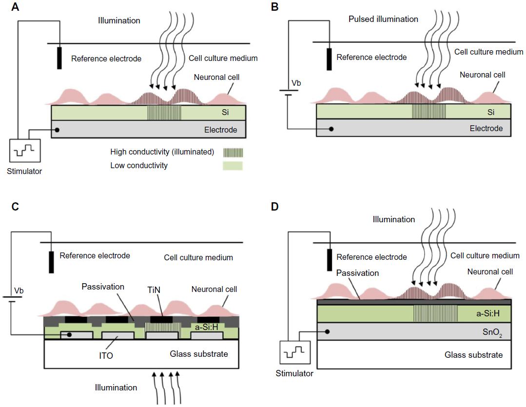 | Figure 1 Photoconductive silicon for neuronal photoactivation. |
Colicos et al were the first to demonstrate this approach.92 Rat hippocampal cells were cultured on an untreated silicon surface immersed in a physiological solution. Stimulation was achieved by targeting a neuron cell body with a constant illumination and modulating the bias voltage between the silicon (which was connected to a base electrode) and an external platinum counter electrode,92 as illustrated in Figure 1A. Illumination, combined with voltage pulses (2 ms, 4 V), stimulated exclusively selected neurons. Stimulation was monitored by changes in the intracellular Ca+2 by a membrane permeable Ca+2 indicator dye. Formation of new synaptic connections in response to specific activity patterns were documented using this technology.
A similar photoconductive stimulation scheme, using single crystal silicon as a photoconducting substrate, was adopted by Starovoytov et al94 and is illustrated in Figure 1B. Here, stimulation is achieved by holding a fixed voltage between the p-type silicon and an Ag/AgCl counter electrode and modulating the laser beam illumination. The silicon wafer was cut into 1.5 cm by 1.5 cm square pieces. The unpolished back side of the silicon wafer was scratched, painted with InGa eutectic, and placed on a flat copper electrode, which was glued using silicone rubber to the bottom side of a petri dish.
Hippocampal neuron activity was monitored by intracellular recordings using a patch-clamp recording. Action potentials could be stimulated with 0.3 mW and 100 μs illumination. Threshold bias values for different neurons, were found to vary over a wide range (−0.4 to −1.5V), and only particular locations on putative axons were susceptible to stimulation. In addition, recorded responses were sometimes characterized by exactly the same latency, even when stimulated over a rather wide area. These effects were explained by electrical current leakage through low-resistivity cross-interface pathways; ie, microscopic holes in the glial layer, or non-uniformities in the semiconductor surface and/or the native oxide. It was hypothesized that most of the electric current escapes through such pathways found in 100-μm disks around the illuminated location, effecting only the pathways traversed by the neurites of the patched cells.94
The temporal and spatial resolution of silicon photoexcitation is limited by minority charge carrier lifetime and diffusion coefficient, which is approximately equal to the thickness of the silicon.99 It was argued that this resolution can be improved by patterning the silicon surface, and thinning the chip.94,100 Another possibility is using low conductivity silicon which can be achieved, for example, by doping the silicon with gold. The recombination centers should reduce the lateral diffusion of photogenerated minority carriers.101,102
a-Si:H was also employed as a photoconductive layer for neuronal activation. A scheme demonstrating neuronal light stimulation using an a-Si:H-based device is presented in Figure 1D. a-Si:H can be thinned to improve the spatial resolution and permit optical access from the top and bottom.97,103 However, owing to its poor stability in the physiological solution, it requires a passivation layer.97 Light addressed recordings of cardiac myocytes, using an array of titanium nitride (TiN) microelectrodes on an a-Si:H photoconductive layer, was reported by Bucher et al.96,104 An a-Si:H layer was sandwiched between indium tin oxide (ITO) leads on a glass substrate, and a layer of microelectrodes embedded in carbonic silicon oxide (SiOx:C) insulation as demonstrated in Figure 1C. The spontaneous activity of cardiac myocytes was recorded upon illumination of the photoconductor with a 488 nm laser beam with a spot diameter of 1.6 μm and intensity of 1.6 mW.96,104
An alternative passivation layer composed of low conductivity zinc antimonite (ZnOSb2O5) was suggested by Suzurikawa et al.97,98 An a-Si:H layer was sandwiched between a tin oxide (SnO2) coated glass substrate and a zinc antimonate passivation layer, as demonstrated in Figure 1D. This waterproof, low-conductivity passivation layer prevents spreading currents along the plane.98 Rat cortical cells were cultured on a photosensitive electrode, coated with poly-D-lysine and laminin for better adhesion. Neuronal activation was achieved using 470–495 nm light with intensity of 800 mW/cm2, and voltage pulses of 3 V for 1 ms, as verified using calcium imaging. In a subsequent study, the authors further improved the simultaneous light stimulation and the Ca+2 imaging experimental system97 by incorporation of a digital micro-mirror device to achieve patterned illumination for neuronal activation. Neuronal responses decreased dramatically at approximately 10 μm from the illumination border, suggesting spatial resolution of a single-cell.
Photoconductive neuronal stimulation technology is comparably simple and can be easily implemented to study neurons in vitro. However, long-term in vitro applications are a challenge due to heating of the tissue. Furthermore, the need to apply bias is a drawback when considering in vivo applications. Other drawbacks include the mechanical difference between the rigid silicon and soft tissue which compromises biocompatibility,105 the limited stability of the device in a biological environment,41 and the need to use high intensity illumination which may damage the cells,106 or result in cell death due to reactive oxygen species (ROS).107,108
In comparison, stimulation of normal and degenerate rat retinas was achieved using photovoltaic silicon with pulsed near IR light at intensities of 0.2–10 mW/mm2 with pulse durations of 0.5–4.0 ms. Photovoltaic silicon cancels the need to apply a bias voltage.34 We now turn to discuss the use of photo induced effects in CPs for neuronal stimulation.
CPs
CPs have been studied extensively in the past few decades for a variety of optoelectronic applications such as solar cells112,113 and light emitting diodes.111,112 When light is absorbed in organic materials, it results in a mobile excited state (excitons), rather than free electron–hole pairs as produced in inorganic materials. This occurs due to weak intermolecular forces and low dielectric permittivity which confines the exciton to a small volume (a few cubic nanometers)113 and creates a large (0.1–1.0 eV) Coulombic barrier to their dissociation into separate electrons and holes.114 Thus, instead of dissociating, the excitons diffuse within the organic layer until they reach an electrode. Exciton diffusion length (typically a few nanometers)115 limits photocurrent generation because most excitons recombinant before reaching the electrode.114,116
To establish efficient photocurrent generation, such devices are based on a heterojunction between an electron-donating and an electron-accepting material, which allows photogenerated excitons to dissociate. At the donor–acceptor interface exciton, dissociation is energetically favored over the exciton state of either donor or acceptor.114 Various donor–acceptor pairs have been investigated so far, including polymer–fullerene,117 polymer–perylene,118,119 polymer–polymer,120 and polymer–QD.121,122
The two main designs of CP photovoltaic devices are planar and bulk heterojunction (BHJ). Planar heterojunction devices rely on the diffusion of excitons to the donor–acceptor interface to achieve charge separation.123,124 The short exciton diffusion length (<10 nm), compared with the absorption depth of the film, limits the thickness of the effective light-harvesting layer. This limitation ultimately reduces the efficiency of photon to electron generation, and thus the effectiveness of photostimulation. BHJ devices are formed by blending the donor and the acceptor species together to achieve phase-segregated architecture.
The BHJ architecture widens the interface between donor and acceptor, maximizes the probability for charge pair separation, and dramatically increases photocurrent generation.117,119 However, this continuous donor–acceptor structure increases the probability for charge recombination in the bulk,123,124 which may reduce photocurrent generation and ultimately diminish the effectiveness of photostimulation.
Harnessing polymers for light stimulation of neurons is conditional for maintaining their photoelectric properties under biological conditions. In particular, oxygen and aqueous solutions may have a negative effect, such as degradation and quenching species. Examples for two photovoltaic polymeric mixtures, which were tested and found stable in aqueous solution conditions include: poly(3-octylthiophene): N2200 (P3OT:N2200)125 and poly(3- hexylthiophene): phenyl-C61-butyric-acid-methyl ester (P3HT:PCBM).126
Ghezzi et al127 demonstrated photostimulation of neurons by a polymeric mixture-based scheme (P3HT:PCBM), illustrated in Figure 2. In this BHJ structure, P3HT is the electron donor, whereas PCBM is the electron acceptor. To achieve the photoactive neuronal interface, an ITO coated glass substrate was spin-coated with the photovoltaic polymer blend, followed by a poly-L-lysine coating to improve cell adhesion. The patch-clamp technique was used to record the electrical activity of primary rat embryonic hippocampal neurons, cultured on the polymer coated surface. In addition, neuronal network activity was characterized by extracellular recording of primary rat embryonic hippocampal neurons, cultured on a polymer coated ITO microelectrode array.
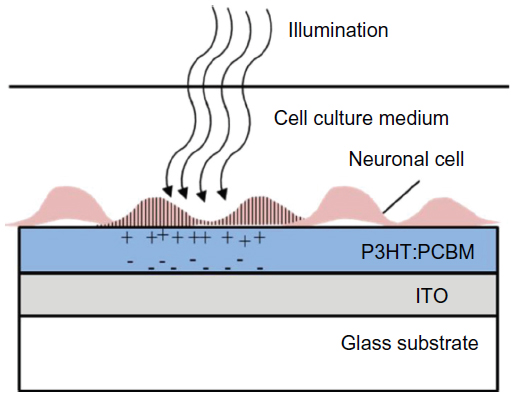 | Figure 2 Conducting polymer for neuronal photoactivation. |
It was found that neuronal viability and network development were not compromised by the P3HT:PCBM film as was demonstrated by cell staining tests. Furthermore, no differences in spontaneous activity and network firing were observed between cells cultured on the P3HT:PCBM coated surfaces and cells cultured on uncoated surfaces. Rapid neuronal excitation was evoked with short light pulses (532 nm) at an intensity of 10 mW/mm2 for 20 ms. Capacitive coupling was suggested as the stimulation mechanism, as no adverse effects were observed on either the polymeric film or the neuronal culture, yet a parallel Faradaic component was not ruled out.
In a subsequent study by the same group, neuronal photostimulation by a photoactive interface composed only of the donor component (P3HT), was demonstrated128 (similar to the scheme illustrated in Figure 2, with the P3HT layer instead of the P3HT:PCBM layer). The use of pure P3HT may reduce material toxicity during light exposure, as fullerene photoexcitation has been reported to produce ROS.129 An ITO substrate was spin-coated with the polymer, followed by poly-L-lysine coating. Viability staining assays and patch-clamp recordings were used to validate biocompatibility. Activation of primary rat hippocampal neurons cultured on a polymer coated substrate was accomplished by light pulses (532 nm, 20 ms, 15 mW/mm2). Trains of repetitive light pulses effectively triggered spiking activity up to an illumination frequency of 10 Hz. Higher frequencies resulted in some of the pulses failing to trigger neuronal stimulation.
Next, P3HT coated substrates were applied to activate retinas explanted from albino rats with light induced photoreceptor degeneration. Retinas were placed on the P3HT-coated ITO or on uncoated ITO in a subretinal configuration, and compared with healthy retinas. Activity was recorded with an extracellular electrode placed at the RGC layer. Light stimulation (10 ms, 4 mW/mm2) elicited spiking activity in degenerated retinas placed on P3HT compared with the activity recorded in control retinas. This response appeared with a typical latency of ~70–100 ms from the light pulse onset and was blocked by tetrodotoxin, a sodium channel blocker. The authors suggested response latency and the persistence of the local field potential indicates that a residual external cells layer, which may include photoreceptors, contributed to RGC firing in the degenerate retinas. These cells will not play a role in realistic conditions of a degenerated retina. Photostimulation threshold was 0.3 μW/mm2 when retinas were placed over P3HT, compared with a threshold of 80 μW/mm2 achieved with retinas placed on uncoated ITO samples. The authors suggested that the stimulation mechanism is charge separation occurring mainly at the interface with the ITO, with minor contributions from carriers generated in the bulk. The accumulation of negative charges at the illuminated polymer surface attracts positive ions from the electrolytic solution, triggering neuronal membrane depolarization.
Stimulation of neurons using CPs as a photoactive layer has many advantages. Foremost, the fabrication of the polymeric interface is simple, and deposition methods such as ink-jet printing, allow the realization of small geometrical patterns. The use of soft polymer coatings may also provide a mechanical buffer between a rigid electrode and the soft tissue.130 A major disadvantage of CPs is their low stability under continuous stimulation, exposure to ultraviolet light, or exposure to heat. During repeated insertion or removal of counter ions, CPs undergo swelling and shrinkage that may gradually degrade their conducting properties.131,132 Additionally, synthetic CPs are often fabricated using complex or toxic polymerization schemes that are not well suited for cell interfacing applications. These residues are often not easily removed. These issues have yet to be tested to fully explore the potential of these materials.
QDs
Semiconducting QDs are nanoparticles (NPs) with versatile absorbing and emitting properties that can be tuned by modifying their size, shape, and composition. Quantum confinement provides these particles with band gaps covering the ultraviolet-visual-near IR range. With high quantum efficiency, photostability, and biocompatibility, QDs are rapidly being applied in biological systems primarily as fluorescent labels in both in vitro and in vivo applications.133–135 QDs are also used in biosensors,136–138 cancer treatment,139,140 and drug delivery.141 Moreover, QDs display unique optoelectronic properties and can generate photocurrent.142 Under some conditions, free electrons or holes can escape the QD confinement and create an electrical current. This property has motivated the use of QDs in photovoltaics, lasers, and light emitting diodes.143–145
Optically excited electron-hole pairs in a QD generate a temporary electric dipole moment.146 It was suggested that the electric field associated with this dipole may be strong enough to generate an action potential in neuronal cells.147 Accordingly, QDs have significant potential in photo stimulation of neuronal cells. The quantum effects also offer the possibility to engineer the spectral sensitivity and electrical response in such QD devices.
Few pioneering studies have indicated the potential use of QDs in the realm of neuronal photo-activation. These studies demonstrated two main approaches to achieve light activation of neurons using QDs. The first approach is to directly wire QDs to the cell membrane,147,148 as illustrated in Figure 3A. Although this scheme has so far failed to result in neuronal photostimulation, the prospects of establishing a very short distance QD–neuron coupling (ie, tens of nanometers) is very promising. The second approach is to use a QD-coated surface in close proximity to neural cells, as illustrated in Figure 3B–D.
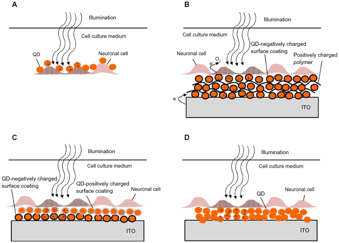 | Figure 3 Quantum dots for neuronal photoactivation. |
Formation of a tightly packed three-dimensional film of QDs should potentially result in strong electronic coupling between the photogenerated exciton, and may enhance the charge carrier separation and transport rate.149 We review below these two approaches.
Direct QD-neuron interface
Placing artificial chromophores, such as QDs at a close proximity to a cell membrane and its ion channels should potentially allow efficient optoelectrical interfacing. Illumination of QDs attached to a cell membrane induces charge separation. The electrical field associated with this separation of charge may activate the neuron, as illustrated in Figure 3A. Direct QD–cell wiring should overcome several major challenges. First, large separation between the cell and a stimulating device leads to poor electrical coupling and low stimulation efficiency. Furthermore, it may provide the ability to target specific cells.
Direct binding of cadmium sulfide (CdS) QDs to neurons was achieved using biological recognition of neuronal cell surface receptors.147,149 Two routes were demonstrated: antibody-antigen recognition and peptide recognition.147 The antibody-antigen approach included a primary antibody binding to a specific cell surface receptor. Multiple secondary antibodies, attached to CdS QDs, bind to the primary antibody. QDs were coated with carboxylic groups to provide linking sites for amine-terminated antibodies. An alternative peptide approach included peptide recognition sequences binding to specific cell surface receptors. These sequences were embedded in the mercaptoacetic acid coating layer of the CdS QDs. The expected separation distance between the QDs and the cell for the indirect antibody-antigen attachment is ~30 nm, assuming no crosslinking of secondary antibodies and a linear attachment, while the direct peptide attachment separation distance is expected to be ~3 nm.147 Both techniques were applied to attach CdS QDs to the SK-N-SH human neuronal cell line. The peptide conjugation technique resulted in reduced particle clustering compared to the antibody technique due to multiple secondary antibody binding and chemically induced cross-linking.
QD-neuron photoelectric interfaces face many challenges. One major challenge is the need to remove the thick surface coating of QDs. This thick coating, ie, polyethylene glycol152 or bovine serum albumin,153,154 used for bio-applications such as labeling and sensing, improves QD-protein targeting capability, biocompatibility, chemical stability, and photostability. However, to achieve an active cell–QD interface, these thick coatings prevent efficient charge transfer, leading to decreased electric field generation. In a subsequent study,148 uncoated, mercaptoacetic acid-capped CdS and cadmium telluride (CdTe) QDs were added to three different nerve cell culture types: SK-N-SH neuronal cell line, PC12 neuronal cell line, and rat neonatal cortical cells. Multiple challenges were identified, starting from cytotoxicity of NPs and nonspecific binding, to rapid endocytosis of the attached NPs inside the cell. To establish a direct QD–neuron interface other solutions should be considered. For example, limiting the number of polyethylene glycol molecules, which constitute the surface coating, and developing new hydrophilic organic ligands, thereby producing a thin and tightly-packed shell. Another approach to diminish cytotoxic effects is by anchoring QDs to a device. This way QDs in contact with cells are neither in a dispersed state nor bound to the cell membrane, thus reducing the probability for endocytosis.
QD nanostructured interface
Several recent studies have demonstrated neuronal photoactivation using QD-based coatings. These surfaces may provide a solution to the biocompatibility challenge mentioned above.
Since QDs are attached to a surface, there is less chance for cellular penetration. Recently, drop casting,150 as well as electrostatic layer-by-layer (LBL)149,155 fabricated QD films were successfully used to achieve photostimulation of cultured neurons.
A mercury telluride (HgTe) QD layer on ITO was used for light activation of cultured neurons by Pappas et al.149 The QD film was prepared using an electrostatic LBL method by layering negatively charged QDs, and positively charged poly(dimethyl-diallyl-ammonium-chloride) (PDDA) on an ITO substrate, as illustrated in Figure 3A. To improve the biocompatibility of the QD coated surface, it was coated with polylysine and poly(acrylic acid). Photostimulation of NG108-15, cells cultured on the QD film was achieved by illumination with a 532 nm laser at 800 mW/cm2 intensity for 500 ms, and recorded using the patch-clamp technique. No oxidative damage or additional cell stimulation was observed upon a train of repetitive pulses. The proposed mechanism for photocurrent generation includes a sequence of photochemical and charge-transfer reactions, and is illustrated in Figure 3B. First, electrons and holes are generated due to excitons formation in response to light absorbance in the HgTe QDs. The photogenerated electrons are then transferred to oxygen in solution. This results in accumulation of holes due to slow electron transport through the LBL NP film. Thus, the measured photocurrent originates from electrons injected from the electrode surface in response to hole accumulation.149 The authors further suggested resistive coupling as a mechanism of neuronal light stimulation.
The illumination intensity used for photostimulation was very high, more than an order of magnitude higher than bright daylight intensity (800 mW/cm2 compared with ~30 mW/cm2, respectively). Clearly, the efficiency of the charge transfer between QDs and activated cells needs further optimization. The resistive coupling mechanism includes the transfer of electrons across the electrode–electrolyte interface, and thus requires that species, on the surface of the electrode or in the solution, are oxidized or reduced. These reactions can lead to irreversible processes that cause electrode or tissue damage.
The LBL approach applied in Pappas et al149 was also adopted by Invitrogen (Carlsbad, CA, USA).155 A nanostructured biocompatible interface, composed of stacks of semiconductor QDs, coated with an adhesion protein layer was prepared (similar to the scheme illustrated in Figure 2A with a protein adhesion layer instead of a polymer-based electrostatic conjugation). NG108 and primary hippocampal neurons were photostimulated.
Three schemes for optical neuronal activation by QD coated surfaces were described by Lugo et al.150 A CdTe QD coated glass or a cadmium selenide (CdSe) QD coated ITO were used as photoactive substrates, on which prostate cancer cells (LnCap) or mice cortical cells were cultured, respectively. The third scheme is based on a glass micropipette probe coated with CdSe QDs. The coated micropipette was placed on a mice cortical cell. Changes in membrane potential and ionic currents, due to light stimulation for all of the described schemes, were recorded by the patch-clamp technique. The CdTe QDs film was fabricated using electrostatic LBL by layering QD films with opposite-polarity surface charges on a glass substrate as illustrated in Figure 3C. CdTe QDs were coated with either 2-mercaptoethylamine for positive charges or thioglycolic acid for negative charges. An additional polylysine layer was applied to enhance LnCap cells attachment. A 430 nm illumination resulted in hyperpolarization of the prostate cancer cells which was attributed to activation of potassium channels, present at a high density in prostate cancer cells.156 QD stimulation depended on the proximity of the cells to the QD film and disappeared when cells were lifted ~20 μm above the film. Furthermore, using a 740 nm light source (longer than the QD absorption cutoff wavelength) no cellular response was observed, confirming the role of QDs in stimulating the cell.150
A CdSe QD coated ITO substrate was prepared by drop casting, as illustrated in Figure 3D. A 550 nm illumination of the film resulted in some mice cortical cells depolarizing and action potential firing, while others hyperpolarized. This variability was attributed to compromised cell viability on the QD film or due to distance variation (between the cells and the substrate).
Finally, hyperpolarization of mice cortical cell membrane was generated by 550 nm illumination of a CdSe QD coated glass micropipette probe by drop casting (similar to the scheme illustrated in Figure 3D, with a glass micropipette instead of an ITO substrate). Photoexcitation of the QD probes often produced little or no response. These results were attributed to variations in the ion channels distribution and cell viability. Excitation effects in all schemes required an intensity of 107 photons/μm2/second.150
Studies aiming to achieve neuronal photostimulation using QDs have so far achieved limited efficiency. A key challenge in harnessing QD technology to activate neurons is the efficiency and the nature of the charge transfer mechanisms. Further understanding of the photocurrent and photo stimulation mechanisms is of utmost importance. QD toxicity in neural applications is crucial to establish a biocompatible QD-based photoactive neural interface. Toxic effects of QDs include changes in cell morphology, suppressed metabolic activity, and a decrease in cell viability157,158 and are attributed mainly to their composition as well as to their surface coating and nanometer size.159
The most predominant cause for QD cytotoxicity is the generation of ROS. ROS diminish cellular respiration, increase permeation of the cell membrane, and damage the nucleus, leading to eventual cell death.159,160 A notable example is the photo-oxidation of cadmium (Cd), a primary constituent in commonly employed QDs (CdSe, CdS, CdTe).161 These ions are thought to bind mitochondrial proteins, diminish cellular respiration, and ultimately lead to cell death.161
The ligand coating the QD surface can also have toxic effects. Ligands such as trioctylphosphene oxide and mercaptoundecanoic acid may cause decreased cell proliferation or DNA damage.162,163 Particle size also contributes to toxicity, with smaller particles found to be more toxic than larger particles,157,164 due to increase in surface to volume ratio,163 (more surface Cd+2 ions are available for reaction). Additional significant challenges include biocompatibility of the whole device and neuron–device coupling.
Summary, challenges, and perspectives
In this review we explored different schemes for light activation of neurons, focusing on novel devices and interfaces. We have surveyed the different schemes for neuronal stimulation with light studied so far, and the advantages and challenges of each scheme were discussed. Table 1 summarizes the pros and cons of the different schemes discussed above.
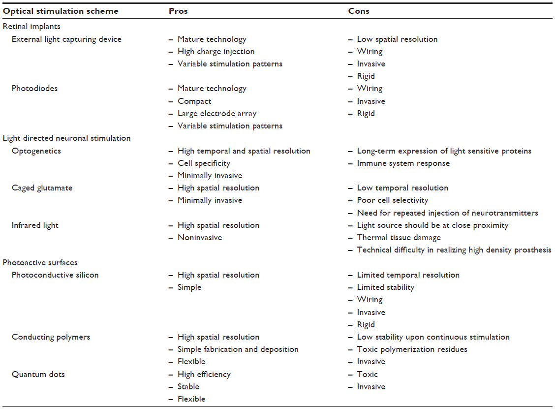 | Table 1 Summary of neuronal optical stimulation schemes |
Recent progress in material engineering and the emergence of new nanomaterials offer many advantages in both light harvesting and interfacing with neurons. Table 2 summarizes the three major schemes for photoactive neuronal surfaces discussed above, including: photoconductive effect of silicon substrate under applied voltage, CPs, and QDs as chromophores for efficient light harvesting and transduction to electrical signal. QDs were either directly conjugated to a neural cell membrane or used to form a photoactive interface.
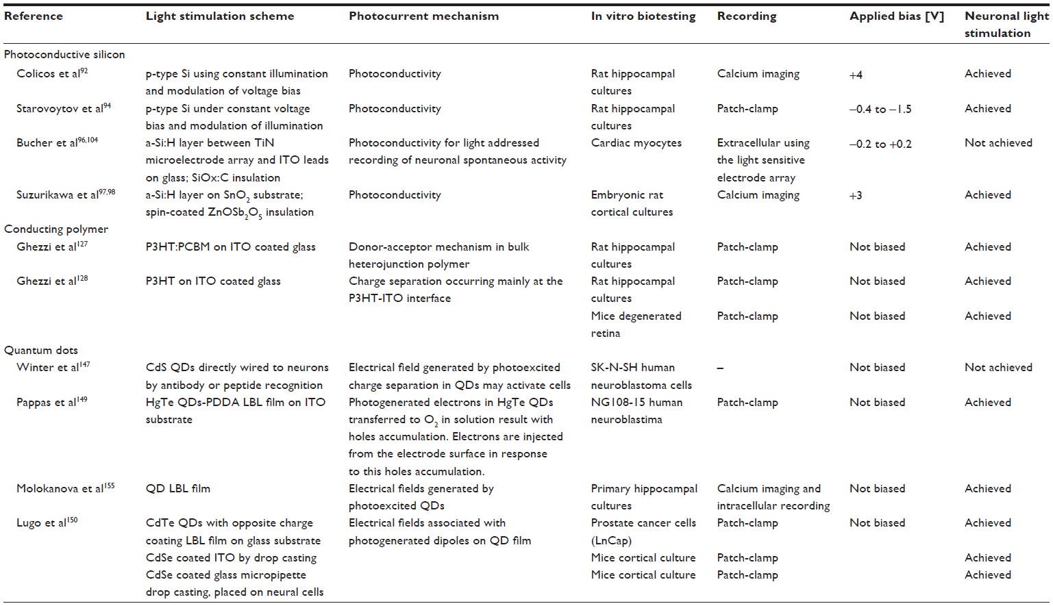 | Table 2 Photoactive neuronal surfaces |
Light directed neural interfaces are in the early stages of development, mostly limited to acute or experimental applications. Key challenges must be overcome before these devices can be used in neural implants for vision restoration. In the next sections we will discuss these challenges and further point out some promising directions in the study of photoactive neuronal interfaces. The first major challenge is to achieve efficient light harvesting and transduction of light into an electrical signal. Neural photoelectrodes should also accommodate the dramatic differences between the tissue and the device: the soft nature of living tissues compared with rigid electronic components, as well as ionic charge transport in tissue compared with electrons and holes conduction in solid state electronic devices. Thus, additional challenges include the safety of the electrochemical interface, as well as meeting mechanical, biocompatibility, and stability requirements.
Light harvesting systems which aim to replace the highly sensitive biological system165 face an incredible challenge for the generation of retinal prostheses. Recently proposed approaches are not sensitive enough and the use of new materials such as QDs and CPs offer exciting alternatives. However, understanding the underlying mechanisms of light harvesting, charge separation, and photocurrent generation in these novel nanostructured devices is still incomplete, and needs further research. Indeed, improving charge transfer efficiency of photoexcited QDs has been under investigation in recent years in the field of solar cell technology.145,166,167 Such solar cells consist of QD coated electrodes embedded in electrolyte-containing charge donors. In the presence of light, charges are injected from a QD matrix into the underlying support electrode, and direct current between a counter electrode in the solution and the QD coated electrode is obtained.164 The QD-electrode-solution coupling is extremely important both for solar cells and neuronal stimulation applications, as the environment may affect charge transport processes as well as the effective band structure of the QDs,168–170 and may result in enhanced or suppressed photocurrent.
As mentioned above, another key barrier that must be overcome for the safe realization of light directed neural interfaces is proper electrochemical charge transfer across the electrode–tissue interface. The electrochemical properties of the stimulating interface, which determine the reactions mediating the transition from electron flow in the electrode to ion flow in the tissue, are fundamental to its performance. The physical reactions taking place during neuronal stimulation, following photoexcitation and photocurrent generation, can be capacitive or faradaic or a combination of the two.8,171 The capacitive mechanism involves the charging and discharging of the photoelectrode–electrolyte double layer, and neuronal membrane/electrolyte interfaces due to redistribution of charged species in the electrolyte. The faradaic mechanism, on the other hand, involves the transfer of electrons across the electrode–electrolyte interface and is associated with oxidation or reduction reactions of species on the surface of the photoelectrode or in the solution.8,171 These reactions may be irreversible and may result in both electrode damage and cell degradation and should be avoided. Therefore, the mechanism of charge injection, as well as the actual amount of charge, is important. As a rule, the ideal situation for safe and long-term neuronal stimulation is capacitive charge delivery.7,172,173
Other critical parameters are flexibility and mechanical compatibility with the neuronal tissue, which are both crucial for extending device life time.105,174,176 Biocompatibility and stability of the device in a biological environment is important to allow long-term in vitro investigations and clearly for retinal prosthetic application.10,39,41
Primarily, understanding the chronic effects of light is highly important. Exposure to high illumination intensity may result in oxidative changes to the membrane or thermal and photonic damage to cells.106 Improvement in the biocompatibility of the photoactive schemes reviewed above remains a major challenge. The photoconductive silicon scheme includes the application of a voltage (see Figure 1) which may result in heating of the tissue. CPs may lose stability in an aqueous solution under illumination, resulting in degradation of conduction properties.131,132 Furthermore, toxic polymerization residues may not be suitable for long-term cell interfacing applications. Finally QDs, especially free in solution, may induce adverse cytotoxicity effects originating from their toxic composition (core and ligands) or from their nanoscale size.177,178 Furthermore, photoexcitation of Cd-based QDs can lead to the generation of free Cd radicals which are thought to bind mitochondrial proteins and may interfere with cellular respiration and lead to cell death.161 To reduce QD toxic effects it is possible to use biocompatible surface coatings such as glutathione or polyethyleneimine or to limit access to the toxic core by coating the particles with a protective layer. For example, coating films of CdTe with collagen or ZnS assemblies with bovine serum albumin157,162 can improve cell viability. In addition, attachment of QDs to a surface may prevent cellular uptake.
To summarize, it is critical to ensure efficient light transduction, efficient electrochemical interfacing, and a proper electrode–neuron interface to ensure both the viability of the tissue and the effectiveness of the photoelectrical interface. Beyond the many challenges and technical difficulties discussed above, a critical impediment in realizing visual prostheses is the ability to faithfully mimic the coding of the retina in a manner suitable for image reconstruction by the brain. These challenges should be addressed before this technique can be widely applied in clinical therapy. Despite many challenges, optical techniques present a promising direction to overcome the fundamental limitations of traditional electrophysiological tools by allowing spatial selectivity and fine control over the stimulated area. QD films and CPs offer exciting possibilities in engineering efficient optoelectrical technologies to investigate neuronal activity and even for substitution of degenerated retina. Promising directions for future nanostructured photoactive neuronal interfaces include utilization of photo-responsive nanowires,180 carbon nanotubes (CNTs),181 and flexible support materials.182
Incorporation of CNTs in the design of a photoactive interface is an approach to enhance the photocurrent and increase biocompatibility. Intensive investigations over the past decade have explored the unique properties of CNTs for neuronal interfacing, including enhanced electrochemical properties, biocompatibility and durability, as well as high electrical conductivity. We have recently reviewed progress in CNT-based microelectrode arrays for neuronal recording and stimulation, and highlighted developments towards a flexible biocompatible CNT-based technology.183 CNTs coupled to chromophores, such as QDs, may further enhance the electrical coupling between the chromophore and neurons. This approach is currently being studied by our group for retinal stimulation applications.181
The coupling of QDs to CNTs has been demonstrated.184–186 Furthermore, CNTs have been used as a linker between a QD matrix and an electrode enhanced generation of a photocurrent.187,188 CNTs provide a very effective adhesive material for neuronal proliferation, and as such, facilitate both strong coupling between the cells and the surface. The inherently electrochemically stable interface, with a capacitive charge transfer mechanism and low impedence is ideal for efficient neuronal stimulation. Improved mechanical and electrical coupling between the cells and the electrodes is also expected when using the CNT–QD scheme. For long-term neural in vivo applications, the flexibility of the photoactive device is highly desirable. Recently, our group has developed a flexible electrode array suited for neuronal recording and stimulation and composed entirely of CNTs.182 Our technology is simple, robust and the resulting stimulating electrodes are nearly purely capacitive. The device was successfully applied for recording and stimulation of a chick retina.182
To conclude, photoactive surfaces have an enormous potential in the realm of neuronal interfaces. The emergence of novel nanomaterials, combined with the implementation of flexible and transparent device support, offers exciting new solutions addressing issues such as efficient light harvesting and transduction to electrical signals, long-term biocompatibility and stability, small size, and improved mechanical properties. The future of these bio-interfacing optoelectronic devices is based upon expanding our understanding of the mechanisms underlying the generation of photocurrent and neuronal photostimulation. At this early stage of the technology, it is still difficult to evaluate which of the many suggested technologies would be the optimal one. As we have discussed above, each technology has advantages and disadvantages, but the overall compatibility of these technologies will have to be revealed through additional testing and long-term use. Additional research would eventually result in more robust technology and may revolutionize the treatment of retinal impairments.
Acknowledgement
The authors are grateful for many useful discussions with Evelyne Sernagor, Uri Banin, Ori Cheshnovsky, and Shlomo Yitzchaik. We also acknowledge the support of a grant from the Israel Ministry of Science and Technology, the Israel Science Foundation, and the European Research Council funding under the European Community’s Seventh Framework Program (FP7/2007–2013)/ERC grant agreement FUNMANIA-306707.
Disclosure
The authors report no conflicts of interest in this work.
References
Plow EB, Pascual-Leone A, Machado A. Brain stimulation in the treatment of chronic neuropathic and non-cancerous pain. J Pain. 2012;13(5):411–424. | |
McCreery DB. Cochlear nucleus auditory prostheses. Hear Res. 2008;242(1–2):64–73. | |
Wichmann T, Delong MR. Deep brain stimulation for neurologic and neuropsychiatric disorders. Neuron. 2006;52(1):197–204. | |
Laxton AW, Tang-Wai DF, McAndrews MP, et al. A phase I trial of deep brain stimulation of memory circuits in Alzheimer’s disease. Ann Neurol. 2010;68(4):521–534. | |
Jackson A, Zimmermann JB. Neural interfaces for the brain and spinal cord – restoring motor function. Nat Rev Neurol. 2012;8(12):690–699. | |
O’Brien EE, Greferath U, Vessey KA, Jobling AI, Fletcher EL. Electronic restoration of vision in those with photoreceptor degenerations. Clin Exp Optom. 2012;95(5):473–483. | |
Cogan SF. Neural stimulation and recording electrodes. Annu Rev Biomed Eng. 2008;10:275–309. | |
Merrill DR, Bikson M, Jefferys JG. Electrical stimulation of excitable tissue: design of efficacious and safe protocols. J Neurosci Methods. 2005;141(2):171–198. | |
McConnell GC, Rees HD, Levey AI, Gutekunst CA, Gross RE, Bellamkonda RV. Implanted neural electrodes cause chronic, local inflammation that is correlated with local neurodegeneration. J Neural Eng. 2009;6(5):056003. | |
Polikov VS, Tresco PA, Reichert WM. Response of brain tissue to chronically implanted neural electrodes. J Neurosci Methods. 2005;148(1):1–18. | |
Nikolenko V, Poskanzer KE, Yuste R. Two-photon photostimulation and imaging of neural circuits. Nat Methods. 2007;4(11):943–950. | |
Szobota S, Isacoff EY. Optical control of neuronal activity. Annu Rev Biophys. 2010;39:329–348. | |
Zrenner E, Bartz-Schmidt KU, Benav H, et al. Subretinal electronic chips allow blind patients to read letters and combine them to words. Proc Biol Sci. 2011;278(1711):1489–1497. | |
Hartong DT, Berson EL, Dryja TP. Retinitis pigmentosa. Lancet. 2006;368(9549):1795–1809. | |
Ferris FL, Fine SL, Hyman L. Age-related macular degeneration and blindness due to neovascular maculopathy. Arch Ophthalmol. 1984;102(11):1640–1642. | |
Stone JL, Barlow WE, Humayun MS, de Juan E Jr, Milam AH. Morphometric analysis of macular photoreceptors and ganglion cells in retinas with retinitis pigmentosa. Arch Ophthalmol. 1992;110(11):1634–1639. | |
Mazzoni F, Novelli E, Strettoi E. Retinal ganglion cells survive and maintain normal dendritic morphology in a mouse model of inherited photoreceptor degeneration. J Neurosci. 2008;28(52):14282–14292. | |
Brindley GS. A new interaction of light and electricity in stimulating the human retina. J Physiol. 1964;171(3):514–520. | |
Brindley GS, Lewin WS. The sensations produced by electrical stimulation of the visual cortex. J Physiol. 1968;196(2):479–493. | |
Potts AM, Inoue J, Buffum D. The electrically evoked response of the visual system (EER). Invest Ophthalmol. 1968;7(3):269–278. | |
Weiland JD, Cho AK, Humayun MS. Retinal prostheses: current clinical results and future needs. Ophthalmology. 2011;118(11):2227–2237. | |
de Balthasar C, Patel S, Roy A, et al. Factors affecting perceptual thresholds in epiretinal prostheses. Invest Ophthalmol Vis Sci. 2008;49(6):2303–2314. | |
Wilke R, Gabel VP, Sachs H, et al. Spatial resolution and perception of patterns mediated by a subretinal 16-electrode array in patients blinded by hereditary retinal dystrophies. Invest Ophthalmol Vis Sci. 2011;52(8):5995–6003. | |
Fujikado T, Kamei M, Sakaguchi H, et al. Testing of semichronically implanted retinal prosthesis by suprachoroidal-transretinal stimulation in patients with retinitis pigmentosa. Invest Ophthalmol Vis Sci. 2011;52(7):4726–4733. | |
Klauke S, Goertz M, Rein S, et al. Stimulation with a wireless intraocular epiretinal implant elicits visual percepts in blind humans. Invest Ophthalmol Vis Sci. 2011;52(1):449–455. | |
Humayun MS, Dorn JD, da Cruz L, et al; Argus II Study Group. Interim results from the international trial of Second Sight’s visual prosthesis. Ophthalmology. 2012;119(4):779–788. | |
Palanker D, Vankov A, Huie P, Baccus S. Design of a high-resolution optoelectronic retinal prosthesis. J Neural Eng. 2005;2(1):S105–S120. | |
DeMarco PJ, Yarbrough GL, Yee CW, et al. Stimulation via a subretinally placed prosthetic elicits central activity and induces a trophic effect on visual responses. Invest Ophthalmol Vis Sci. 2007;48(2):916–926. | |
Chow AY, Bittner AK, Pardue MT. The artificial silicon retina in retinitis pigmentosa patients (an American Ophthalmological Association thesis). Trans Am Ophthalmol Soc. 2010;108:120–154. | |
Ahuja AK, Dorn JD, Caspi A, et al; Argus II Study Group. Blind subjects implanted with the Argus II retinal prosthesis are able to improve performance in a spatial-motor task. Br J Ophthalmol. 2011;95(4):539–543. | |
Keserü M, Feucht M, Bornfeld N, et al. Acute electrical stimulation of the human retina with an epiretinal electrode array. Acta Ophthalmol. 2012;90(1):e1–e8. | |
Loudin JD, Simanovskii DM, Vijayraghavan K, et al. Optoelectronic retinal prosthesis: system design and performance. J Neural Eng. 2007;4(1):S72–S84. | |
Wang L, Mathieson K, Kamins TI, et al. Photovoltaic retinal prosthesis: implant fabrication and performance. J Neural Eng. 2012;9(4):046014. | |
Mathieson K, Loudin J, Goetz G, et al. Photovoltaic Retinal Prosthesis with High Pixel Density. Nat Photonics. 2012;6(6):391–397. | |
Chow AY, Chow VY, Packo KH, Pollack JS, Peyman GA, Schuchard R. The artificial silicon retina microchip for the treatment of vision loss from retinitis pigmentosa. Arch Ophthalmol. 2004;122(4):460–469. | |
Szarowski DH, Andersen MD, Retterer S, et al. Brain responses to micro-machined silicon devices. Brain Res. 2003;983(1–2):23–35. | |
Biran R, Martin DC, Tresco PA. Neuronal cell loss accompanies the brain tissue response to chronically implanted silicon microelectrode arrays. Exp Neurol. 2005;195(1):115–126. | |
Schwahn HN, Gekeler F, Kohler K, et al. Studies on the feasibility of a subretinal visual prosthesis: data from Yucatan micropig and rabbit. Graefes Arch Clin Exp Ophthalmol. 2001;239(12):961–967. | |
Guenther E, Tröger B, Schlosshauer B, Zrenner E. Long-term survival of retinal cell cultures on retinal implant materials. Vision Res. 1999;39(24):3988–3994. | |
Potter KA, Buck AC, Self WK, Capadona JR. Stab injury and device implantation within the brain results in inversely multiphasic neuroinflammatory and neurodegenerative responses. J Neural Eng. 2012;9(4):046020. | |
Hämmerle H, Kobuch K, Kohler K, Nisch W, Sachs H, Stelzle M. Biostability of micro-photodiode arrays for subretinal implantation. Biomaterials. 2002;23(3):797–804. | |
Deisseroth K. Optogenetics. Nat Methods. 2011;8(1):26–29. | |
Lagali PS, Balya D, Awatramani GB, et al. Light-activated channels targeted to ON bipolar cells restore visual function in retinal degeneration. Nat Neurosci. 2008;11(6):667–675. | |
Lima SQ, Miesenböck G. Remote control of behavior through genetically targeted photostimulation of neurons. Cell. 2005;121(1):141–152. | |
Kramer RH, Fortin DL, Trauner D. New photochemical tools for controlling neuronal activity. Curr Opin Neurobiol. 2009;19(5):544–552. | |
Richter CP, Matic AI, Wells JD, Jansen ED, Walsh JT. Neural stimulation with optical radiation. Laser Photon Rev. 2011;5(1):68–80. | |
Hirase H, Nikolenko V, Goldberg JH, Yuste R. Multiphoton stimulation of neurons. J Neurobiol. 2002;51(3):237–247. | |
Zemelman BV, Lee GA, Ng M, Miesenböck G. Selective photostimulation of genetically chARGed neurons. Neuron. 2002;33(1):15–22. | |
Bayley H. Ion channels get flashy. Nat Chem Biol. 2006;2(1):11–13. | |
Bi AD, Cui JJ, Ma YP, et al. Ectopic expression of a microbial-type rhodopsin restores visual responses in mice with photoreceptor degeneration. Neuron. 2006;50(1):23–33. | |
Arrenberg AB, Stainier DY, Baier H, Huisken J. Optogenetic control of cardiac function. Science. 2010;330(6006):971–974. | |
Cardin JA, Carlén M, Meletis K, et al. Targeted optogenetic stimulation and recording of neurons in vivo using cell-type-specific expression of Channelrhodopsin-2. Nat Protoc. 2010;5(2):247–254. | |
Frydrych M, Silfsten P, Parkkinen S, Parkkinen J, Jaaskelainen T. Color sensitive retina based on bacteriorhodopsin. Biosystems. 2000;54(3):131–140. | |
Zhang F, Wang LP, Brauner M, et al. Multimodal fast optical interrogation of neural circuitry. Nature. 2007;446(7136):633–639. | |
Reutsky-Gefen I, Golan L, Farah N, et al. Holographic optogenetic stimulation of patterned neuronal activity for vision restoration. Nat Commun. 2013;4:1509. | |
Gradinaru V, Thompson KR, Zhang F, et al. Targeting and readout strategies for fast optical neural control in vitro and in vivo. J Neurosci. 2007;27(52):14231–14238. | |
Zhang F, Gradinaru V, Adamantidis AR, et al. Optogenetic interrogation of neural circuits: technology for probing mammalian brain structures. Nat Protoc. 2010;5(3):439–456. | |
Claridge-Chang A, Roorda RD, Vrontou E, et al. Writing memories with light-addressable reinforcement circuitry. Cell. 2009;139(2):405–415. | |
Callaway EM, Katz LC. Photostimulation using caged glutamate reveals functional circuitry in living brain slices. Proc Natl Acad Sci U S A. 1993;90(16):7661–7665. | |
Wieboldt R, Gee KR, Niu L, Ramesh D, Carpenter BK, Hess GP. Photolabile precursors of glutamate: synthesis, photochemical properties, and activation of glutamate receptors on a microsecond time scale. Proc Natl Acad Sci U S A. 1994;91(19):8752–8756. | |
Dalva MB, Katz LC. Rearrangements of synaptic connections in visual cortex revealed by laser photostimulation. Science. 1994;265(5169):255–258. | |
Kandler K, Katz LC, Kauer JA. Focal photolysis of caged glutamate produces long-term depression of hippocampal glutamate receptors. Nat Neurosci. 1998;1(2):119–123. | |
Svoboda K, Yasuda R. Principles of two-photon excitation microscopy and its applications to neuroscience. Neuron. 2006;50(6):823–839. | |
Callaway EM, Yuste R. Stimulating neurons with light. Curr Opin Neurobiol. 2002;12(5):587–592. | |
Fino E, Araya R, Peterka DS, Salierno M, Etchenique R, Yuste R. RuBi-Glutamate: Two-Photon and Visible-Light Photoactivation of Neurons and Dendritic spines. Front Neural Circuits. 2009;3:2. | |
Verde EMR, Zayat L, Etchenique R,Yuste R. Photorelease of gaba with visible light using an inorganic caging group. Front Neural Circuits. 2008;2:2. | |
Cürten B, Kullmann PH, Bier ME, Kandler K, Schmidt BF. Synthesis, photophysical, photochemical and biological properties of caged GABA, 4-[[(2H-1-benzopyran-2-one-7-amino-4-methoxy) carbonyl] amino] butanoic acid. Photochem Photobiol. 2005;81(3):641–648. | |
Shembekar VR, Chen Y, Carpenter BK, Hess GP. Coumarin-caged glycine that can be photolyzed within 3 microseconds by visible light. Biochemistry. 2007;46(18):5479–5484. | |
Papageorgiou G, Beato M, Ogden D. Synthesis and photolytic evaluation of a nitroindoline-caged glycine with a side chain of high negative charge for use in neuroscience. Tetrahedron. 2011;67(29):5228–5234. | |
Polosukhina A, Litt J, Tochitsky I, et al. Photochemical restoration of visual responses in blind mice. Neuron. 2012;75(2):271–282. | |
Rossi FM, Margulis M, Tang CM, Kao JP. N-Nmoc-L-glutamate, a new caged glutamate with high chemical stability and low pre-photolysis activity. J Biol Chem. 1997;272(52):32933–32939. | |
Pettit DL, Wang SS, Gee KR, Augustine GJ. Chemical two-photon uncaging: a novel approach to mapping glutamate receptors. Neuron. 1997;19(3):465–471. | |
Szobota S, Gorostiza P, Del Bene F, et al. Remote control of neuronal activity with a light-gated glutamate receptor. Neuron. 2007;54(4):535–545. | |
Fenno L, Yizhar O, Deisseroth K. The development and application of optogenetics. Annu Rev Neurosci. 2011;34:389–412. | |
Rogan SC, Roth BL. Remote control of neuronal signaling. Pharmacol Rev. 2011;63(2):291–315. | |
Wells J, Kao C, Jansen ED, Konrad P, Mahadevan-Jansen A. Application of infrared light for in vivo neural stimulation. J Biomed Opt. 2005;10(6):064003. | |
Wells J, Kao C, Mariappan K, et al. Optical stimulation of neural tissue in vivo. Opt Lett. 2005;30(5):504–506. | |
McCaughey RG, Chlebicki C, Wong BJ. Novel wavelengths for laser nerve stimulation. Lasers Surg Med. 2010;42(1):69–75. | |
Duke AR, Cayce JM, Malphrus JD, Konrad P, Mahadevan-Jansen A, Jansen ED. Combined optical and electrical stimulation of neural tissue in vivo. J Biomed Opt. 2009;14(6):060501. | |
Fried NM, Lagoda GA, Scott NJ, Su LM, Burnett AL. Noncontact stimulation of the cavernous nerves in the rat prostate using a tunable-wavelength thulium fiber laser. J Endourol. 2008;22(3):409–413. | |
Teudt IU, Nevel AE, Izzo AD, Walsh JT, Richter CP. Optical stimulation of the facial nerve: a new monitoring technique? Laryngoscope. 2007;117(9):1641–1647. | |
Izzo AD, Richter CP, Jansen ED, Walsh JT. Laser stimulation of the auditory nerve. Lasers Surg Med. 2006;38(8):745–753. | |
Richter CP, Bayon R, Izzo AD, et al. Optical stimulation of auditory neurons: effects of acute and chronic deafening. Hear Res. 2008;242(1–2):42–51. | |
Littlefield PD, Vujanovic I, Mundi J, Matic AI, Richter CP. Laser stimulation of single auditory nerve fibers. Laryngoscope. 2010;120(10):2071–2082. | |
Rajguru SM, Matic AI, Robinson AM, et al. Optical cochlear implants: evaluation of surgical approach and laser parameters in cats. Hear Res. 2010;269(1–2):102–111. | |
Schultz M, Baumhoff P, Maier H, et al. Nanosecond laser pulse stimulation of the inner ear-a wavelength study. Biomed Opt Express. 2012;3(12):3332–3345. | |
Dittami GM, Rajguru SM, Lasher RA, Hitchcock RW, Rabbitt RD. Intracellular calcium transients evoked by pulsed infrared radiation in neonatal cardiomyocytes. J Physiol. 2011;589(Pt 6):1295–1306. | |
Wininger FA, Schei JL, Rector DM. Complete optical neurophysiology: toward optical stimulation and recording of neural tissue. Appl Opt. 2009;48(10):D218–D224. | |
Wells J, Kao C, Konrad P, et al. Biophysical mechanisms of transient optical stimulation of peripheral nerve. Biophys J. 2007;93(7):2567–2580. | |
Goyal V, Rajguru S, Matic AI, Stock SR, Richter CP. Acute damage threshold for infrared neural stimulation of the cochlea: functional and histological evaluation. Anat Rec (Hoboken). 2012;295(11):1987–1999. | |
Zhang XG. Electrochemistry of silicon and its oxide. New York: Springer; 2001. | |
Colicos MA, Collins BE, Sailor MJ, Goda Y. Remodeling of synaptic actin induced by photoconductive stimulation. Cell. 2001;107(5):605–616. | |
Goda Y, Colicos MA. Photoconductive stimulation of neurons cultured on silicon wafers. Nat Protoc. 2006;1(1):461–467. | |
Starovoytov A, Choi J, Seung HS. Light-directed electrical stimulation of neurons cultured on silicon wafers. J Neurophysiol. 2005;93(2):1090–1098. | |
Bucher V, Brugger J, Kern D, Kim GM, Schubert M, Nisch W. Electrical properties of light-addressed sub-mu m electrodes fabricated by use of nanostencil-technology. Microelectronic Engineering. 2002;61–62:2971–2980. | |
Bucher V, Brunner B, Leibrock C, Schubert M, Nisch W. Electrical properties of a light-addressable microelectrode chip with high electrode density for extracellular stimulation and recording of excitable cells. Biosens Bioelectron. 2001;16(3):205–210. | |
Suzurikawa J, Nakao M, Jimbo Y, Kanzaki R, Takahashi H. Light-addressed stimulation under Ca(2+) imaging of cultured neurons. IEEE Trans Biomed Eng. 2009;56(11):2660–2665. | |
Suzurikawa J, Takahashi H, Kanzaki R, Nakao M, Takayama Y, Jimbo Y. Light-addressable electrode with hydrogenated amorphous silicon and low-conductive passivation layer for stimulation of cultured neurons. Applied Physics Letters. 2007;90(9):093901. | |
Bousse L, Mostarshed S, Hafeman D, Sartore M, Adami M, Nicolini C. Investigation of carrier transport through slicon-wafers by photocurrent measurements. J Appl Phys. 1994;75(8):4000–4008. | |
Parak WJ, Hofmann UG, Gaub HE, Owicki JC. Lateral resolution of light-addressable potentiometric sensors: An experimental and theoretical investigation. Sens Actuators A Phys. 1997;63(1):47–57. | |
Valdinoci M, Colalongo L, Pellegrini A, Rudan M. Analysis of conductivity degradation in gold/platinum- doped silicon. IEEE Trans Electron Devices. 1996;43(12):2269–2275. | |
Kaganovich EB, Kizyak IM, Kirillova SI, et al. Photoluminescent and electronic properties of nanocrystalline silicon doped with gold. Semiconductors. 2002;36(9):1027–1032. | |
Moritz W, Yoshinobu T, Finger F, Krause S, Martin-Fernandez M, Schöning MJ. High resolution LAPS using amorphous silicon as the semiconductor material. Sens Actuators B Chem. 2004;103(1–2):436–441. | |
Bucher V, Schubert M, Kern D, Nisch W. Light-addressed sub-mum electrodes for extracellular recording and stimulation of excitable cells. Microelectron Eng. 2001;57–58:705–712. | |
Wester BA, Lee RH, LaPlaca MC. Development and characterization of in vivo flexible electrodes compatible with large tissue displacements. J Neural Eng. 2009;6(2):024002. | |
Wu J, Seregard S, Algvere PV. Photochemical damage of the retina. Surv Ophthalmol. 2006;51(5):461–481. | |
del Olmo-Aguado S, Manso AG, Osborne NN. Light might directly affect retinal ganglion cell mitochondria to potentially influence function. Photochem Photobiol. 2012;88(6):1346–1355. | |
Peng TI, Jou MJ. Mitochondrial swelling and generation of reactive oxygen species induced by photoirradiation are heterogeneously distributed. Mitochondrial Pathogenesis: From Genes and Apoptosis to Aging and Disease. 2006;1011:112–122. | |
Chen J, Cao Y. Development of novel conjugated donor polymers for high-efficiency bulk-heterojunction photovoltaic devices. Acc Chem Res. 2009;42(11):1709–1718. | |
Helgesen M, Søndergaard R, Krebs FC. Advanced materials and processes for polymer solar cell devices. J Mater Chem. 2010;20(1):36–60. | |
Kalyani NT, Dhoble SJ. Organic light emitting diodes: Energy saving lighting technology-a review. Renewable and Sustainable Energy Reviews. 2012;16(5):2696–2723. | |
Alsalhi MS, Alam J, Dass LA, Raja M. Recent advances in conjugated polymers for light emitting devices. Int J Mol Sci. 2011;12(3):2036–2054. | |
Barth S, Bässler H. Intrinsic photoconduction in PPV-type conjugated polymers. Phys Rev Lett. 1997;79(22):4445–4448. | |
Janssen RAJ, Nelson J. Factors limiting device efficiency in organic photovoltaics. Advanced Materials. 2013;25(13):1847–1858. | |
Halls JJM, Pichler K, Friend RH, Moratti SC, Holmes AB. Exciton diffusion and dissociation in a poly(p – phenylenevinylene)/c-60 heterojunction photovoltaic cell. Appl Phys Lett. 1996;68(22):3120–3122. | |
Blom PWM, Mihailetchi VD, Koster LJA, Markov DE. Device physics of polymer: Fullerene bulk heterojunction solar cells. Advanced Materials. 2007;19(12):1551–1566. | |
Brabec CJ, Gowrisanker S, Halls JJM, Laird D, Jia S, Williams SP. Polymer-fullerene bulk-heterojunction solar cells. Advanced Materials. 2010;22(34):3839–3856. | |
Kozma E, Catellani M. Perylene diimides based materials for organic solar cells. Dyes and Pigments. 2013;98(1):160–179. | |
Li C, Wonneberger H. Perylene imides for organic photovoltaics: yesterday, today, and tomorrow. Advanced Materials. 2012;24(5):613–636. | |
Liu Y, Larsen-Olsen TT, Zhao XG, et al. All polymer photovoltaics: From small inverted devices to large roll-to-roll coated and printed solar cells. Solar Energy Materials and Solar Cells. 2013;112:157–162. | |
Wei HT, Zhang H, Sun HZ, Yang B. Preparation of polymer-nanocrystals hybrid solar cells through aqueous approaches. Nano Today. 2012;7(4):316–326. | |
Tang A, Qu S, Teng F, Hou Y, Wang Y, Wang Z. Recent developments of hybrid nanocrystal/polymer bulk heterojunction solar cells. J Nanosci Nanotechnol. 2011;11(11):9384–9394. | |
Li G, Zhu R, Yang Y. Polymer solar cells. Nature Photonics. 2012;6(3):153–161. | |
Nelson J. Organic photovoltaic films. Curr Opin Solid State Mater Sci. 2002;6(1):87–95. | |
Gautam V, Bag M, Narayan KS. Single-pixel, single-layer polymer device as a tricolor sensor with signals mimicking natural photoreceptors. J Am Chem Soc. 2011;133(44):17942–17949. | |
Antognazza MR, Ghezzi D, Musitelli D, Garbugli M, Lanzani G. A hybrid solid-liquid polymer photodiode for the bioenvironment. Appl Phys Lett. 2009;94(24):243501. | |
Ghezzi D, Antognazza MR, Dal Maschio M, Lanzarini E, Benfenati F, Lanzani G. A hybrid bioorganic interface for neuronal photoactivation. Nat Commun. 2011;2:166. | |
Ghezzi D, Antognazza MR, Maccarone R, et al. A polymer optoelectronic interface restores light sensitivity in blind rat retinas. Nature Photonics. 2013;7:400–406. | |
Kong L, Zepp RG. Production and consumption of reactive oxygen species by fullerenes. Environ Toxicol Chem. 2012;31(1):136–143. | |
Nyberg T, Shimada A, Torimitsu K. Ion conducting polymer microelectrodes for interfacing with neural networks. J Neurosci Methods. 2007;160(1):16–25. | |
Marciniak S, Crispin X, Uvdal K, et al. Light induced damage in poly(3,4-ethylenedioxythiophene) and its derivatives studied by photoelectron spectroscopy. Synthetic Metals. 2004;141(1–2):67–73. | |
Yamato H, Ohwa M, Wernet W. Stability of polypyrrole and poly(3,4-ethylenedioxythiophene) for biosensor application. Journal of Electroanalytical Chemistry. 1995;397(1–2):163–170. | |
Singh R, Nalwa HS. Medical applications of nanoparticles in biological imaging, cell labeling, antimicrobial agents, and anticancer nanodrugs. J Biomed Nanotechnol. 2011;7(4):489–503. | |
Wang C, Gao X, Su X. In vitro and in vivo imaging with quantum dots. Anal Bioanal Chem. 2010;397(4):1397–1415. | |
Mahmoudi M, Serpooshan V, Laurent S. Engineered nanoparticles for biomolecular imaging. Nanoscale. 2011;3(8):3007–3026. | |
Qian J, Zhang CY, Cao XD, Liu SQ. Versatile immunosensor using a quantum dot coated silica nanosphere as a label for signal amplification. Anal Chem. 2010;82(15):6422–6429. | |
Bally M, Vörös J. Nanoscale labels: nanoparticles and liposomes in the development of high-performance biosensors. Nanomedicine (Lond). 2009;4(4):447–467. | |
Martín-Palma RJ, Manso M, Torres-Costa V. Optical biosensors based on semiconductor nanostructures. Sensors (Basel). 2009;9(7):5149–5172. | |
Tan A, Yildirimer L, Rajadas J, De La Peña H, Pastorin G, Seifalian A. Quantum dots and carbon nanotubes in oncology: a review on emerging theranostic applications in nanomedicine. Nanomedicine (Lond). 2011;6(6):1101–1114. | |
Luo GP, Long J, Zhang B, et al. Quantum dots in cancer therapy. Expert Opin Drug Deliv. 2012;9(1):47–58. | |
Doane TL, Burda C. The unique role of nanoparticles in nanomedicine: imaging, drug delivery and therapy. Chem Soc Rev. 2012;41(7):2885–2911. | |
Ruland A, Schulz-Drost C, Sgobba V, Guldi DM. Enhancing photocurrent efficiencies by resonance energy transfer in CdTe quantum dot multilayers: towards rainbow solar cells. Adv Mater. 2011;23(39):4573–4577. | |
Dai Q, Duty CE, Hu MZ. Semiconductor-nanocrystals-based white light-emitting diodes. Small. 2010;6(15):1577–1588. | |
Rafailov EU, Cataluna MA, Sibbett W. Mode-locked quantum-dot lasers. Nature Photonics. 2007;1(7):395–401. | |
Kamat PV. Boosting the efficiency of quantum dot sensitized solar cells through modulation of interfacial charge transfer. Acc Chem Res. 2012;45(11):1906–1915. | |
Wang Y, Herron N. Nanometer-sized semiconductot clusters-material synthesis, quantum size effects, and photophysical properties. J Phys Chem. 1991;95(2):525–532. | |
Winter JO, Liu TY, Korgel BA, Schmidt CE. Recognition molecule directed interfacing between semiconductor quantum dots and nerve cells. Advanced Materials. 2001;13(22):1673–1677. | |
Gomez N, Winter JO, Shieh F, Saunders AE, Korgel BA, Schmidt CE. Challenges in quantum dot-neuron active interfacing. Talanta. 2005;67(3):462–471. | |
Pappas TC, Wickramanyake WMS, Jan E, et al. Nanoscale engineering of a cellular interface with semiconductor nanoparticle films for photoelectric stimulation of neurons. Nano Lett. 2007;7(2):513–519. | |
Lugo K, Miao XY, Rieke F, Lin LY. Remote switching of cellular activity and cell signaling using light in conjunction with quantum dots. Biomedical Optics Express. 2012;3(3):447–454. | |
Jokerst JV, Lobovkina T, Zare RN, Gambhir SS. Nanoparticle pegylation for imaging and therapy. Nanomedicine (Lond). 2011;6(4):715–728. | |
Maldiney T, Richard C, Seguin J, Wattier N, Bessodes M, Scherman D. Effect of core diameter, surface coating, and PEG chain length on the biodistribution of persistent luminescence nanoparticles in mice. ACS Nano. 2011;5(2):854–862. | |
Nakane Y, Sasaki A, Kinjo M, Jin T. Bovine serum albumin-coated quantum dots as a cytoplasmic viscosity probe in a single living cell. Analytical Methods. 2012;4(7):1903–1905. | |
Selim KMK, Kang IK, Guo HQ. Albumin-conjugated cadmium sulfide nanoparticles and their interaction with KB cells. Macromolecular Research. 2009;17(6):403–410. | |
Molokanova E, Bartel JA, Zhao W, et al. Quantum dots move beyond fluorescence imaging. Biophotonics. 2008. Available from http://photonics.com/Article.aspx?AID=33995. Accessed November 4, 2013. | |
Prevarskaya N, Skryma R, Bidaux G, Flourakis M, Shuba Y. Ion channels in death and differentiation of prostate cancer cells. Cell Death Differ. 2007;14(7):1295–1304. | |
Lovric´ J, Bazzi HS, Cuie Y, Fortin GR, Winnik FM, Maysinger D. Differences in subcellular distribution and toxicity of green and red emitting CdTe quantum dots. J Mol Med (Berl). 2005;83(5):377–385. | |
Chan WH, Shiao NH, Lu PZ. CdSe quantum dots induce apoptosis in human neuroblastoma cells via mitochondrial-dependent pathways and inhibition of survival signals. Toxicol Lett. 2006;167(3):191–200. | |
Kotov NA, Winter JO, Clements IP, et al. Nanomaterials for neural interfaces. Advanced Materials. 2009;21(40):3970–4004. | |
Lovrić J, Cho SJ, Winnik FM, Maysinger D. Unmodified cadmium telluride quantum dots induce reactive oxygen species formation leading to multiple organelle damage and cell death. Chem Biol. 2005;12(11):1227–1234. | |
Derfus AM, Chan WCW, Bhatia SN. Probing the cytotoxicity of semiconductor quantum dots. Nano Lett. 2004;4(1):11–18. | |
Hoshino A, Fujioka K, Oku T, et al. Physicochemical properties and cellular toxicity of nanocrystal quantum dots depend on their surface modification. Nano Lett. 2004;4(11):2163–2169. | |
Kirchner C, Liedl T, Kudera S, et al. Cytotoxicity of colloidal cdse and cdse/zns nanoparticles. Nano Lett. 2005;5(2):331–338. | |
Shiohara A, Hoshino A, Hanaki K, Suzuki K, Yamamoto K. On the cyto-toxicity caused by quantum dots. Microbiol Immunol. 2004;48(9):669–675. | |
Masland RH. The fundamental plan of the retina. Nature Neuroscience. 2001;4(9):877–886. | |
Hillhouse HW, Beard MC. Solar cells from colloidal nanocrystals: fundamentals, materials, devices, and economics. Curr Opin Colloid Interface Sci. 2009;14(4):245–259. | |
Huang XY, Han SY, Huang W, Liu XG. Enhancing solar cell efficiency: the search for luminescent materials as spectral converters. Chemical Society Reviews. 2013;42(1):173–201. | |
Dibbell RS, Youker DG, Watson DF. Excited-state electron transfer from cds quantum dots to tio2 nanoparticles via molecular linkers with phenylene bridges. J Phys Chem C. 2009;113(43):18643–18651. | |
Flory F, Escoubas L, Berginc G. Optical properties of nanostructured materials: a review. J Nanophoton. 2011;5(1):052502. | |
Park Y, Advincula RC. Hybrid semiconductor nanoparticles: Pi-conjugated ligands and nanostructured films. Chemistry of Materials. 2011;23(19):4273–4294. | |
Bard AJ, Falkner LR. Electrochemical Methods: Fundamentals and Applications. 2nd ed. New York: Wiley Global Education; 2000. | |
McCreery DB, Agnew WF, Yuen TG, Bullara LA. Comparison of neural damage induced by electrical stimulation with faradaic and capacitor electrodes. Ann Biomed Eng. 1988;16(5):463–481. | |
McCreery DB, Agnew WF, Yuen TG, Bullara L. Charge density and charge per phase as cofactors in neural injury induced by electrical stimulation. IEEE Trans Biomed Eng. 1990;37(10):996–1001. | |
Bae SH, Che JH, Seo JM, et al. In vitro biocompatibility of various polymer-based microelectrode arrays for retinal prosthesis. Invest Ophthalmol Vis Sci. 2012;53(6):2653–2657. | |
Brown XQ, Ookawa K, Wong JY. Evaluation of polydimethylsiloxane scaffolds with physiologically-relevant elastic moduli: interplay of substrate mechanics and surface chemistry effects on vascular smooth muscle cell response. Biomaterials. 2005;26(16):3123–3129. | |
Hassler C, Boretius T, Stieglitz T. Polymers for neural implants. J Polym Sci B Polym Phys. 2011;49(1):18–33. | |
Sharifi S, Behzadi S, Laurent S, Forrest ML, Stroeve P, Mahmoudi M. Toxicity of nanomaterials. Chem Soc Rev. 2012;41(6):2323–2343. | |
Rzigalinski BA, Strobl JS. Cadmium-containing nanoparticles: perspectives on pharmacology and toxicology of quantum dots. Toxicol Appl Pharmacol. 2009;238(3):280–288. | |
Sinani VA, Koktysh DS, Yun BG, et al. Collagen coating promotes biocompatibility of semiconductor nanoparticles in stratified lbl films. Nano Lett. 2003;3(9):1177–1182. | |
Khraiche ML, Silva GA, Cauwenberghs G et al inventors; The Regents of the University of California, assignee. Ultra-high photosensitivity vertical nanowire arrays for retinal prosthesis. United States patent WO2011163262 A2. 2011 Jun 21. | |
Banin U, Yitzchaik S, Cheshnovsky O, Hanein Y, Sernagor E, inventor; Yissum Research Development Company of the Hebrew University of Jerusalem, Ltd, 1, assignee. Photoelectrical devices for stimulating neurons. United States patent US20120197364 A1. August 2, 2012. | |
David-Pur M, Bareket-Keren L, Beit-Ya’akov G, Raz-Prag D, Hanein Y. All-carbon nanotube flexible multi-electrode array for neuronal recording and stimulation.. Biomedical Microdevices. In press 2013. | |
Bareket-Keren L, Hanein Y. Carbon nanotube-based multi electrode arrays for neuronal interfacing: progress and prospects. Front Neural Circuits. 2013;6:122. | |
Lei ZL, Wei XY, Zhang L, Bi SX. Preparation and characterization of carbon nanotubes-polymer/CdSe hybrid nanocomposites through combining electrostatic adsorption and ATRP technique. Colloids Surf A Physicochem Eng Asp. 2008;324(1–3):131–136. | |
Banerjee S, Wong SS. In situ quantum dot growth on multiwalled carbon nanotubes. J Am Chem Soc. 2003;125(34):10342–10350. | |
Juarez BH, Klinke C, Kornowski A, Weller H. Quantum dot attachment and morphology control by carbon nanotubes. Nano Lett. 2007;7(12):3564–3568. | |
Scarselli M, Scilletta C, Tombolini F, et al. Photon harvesting with multi wall carbon nanotubes. Superlattices and Microstructures. 2009;46(1–2):340–346. | |
El Khakani MA, Le Borgne V, Aissa B, et al. Photocurrent generation in random networks of multiwall- carbon-nanotubes grown by an “all-laser” process. Appl Phys Lett. 2009;95(8):083114. |
 © 2014 The Author(s). This work is published and licensed by Dove Medical Press Limited. The full terms of this license are available at https://www.dovepress.com/terms.php and incorporate the Creative Commons Attribution - Non Commercial (unported, v3.0) License.
By accessing the work you hereby accept the Terms. Non-commercial uses of the work are permitted without any further permission from Dove Medical Press Limited, provided the work is properly attributed. For permission for commercial use of this work, please see paragraphs 4.2 and 5 of our Terms.
© 2014 The Author(s). This work is published and licensed by Dove Medical Press Limited. The full terms of this license are available at https://www.dovepress.com/terms.php and incorporate the Creative Commons Attribution - Non Commercial (unported, v3.0) License.
By accessing the work you hereby accept the Terms. Non-commercial uses of the work are permitted without any further permission from Dove Medical Press Limited, provided the work is properly attributed. For permission for commercial use of this work, please see paragraphs 4.2 and 5 of our Terms.