")
Back to Journals » International Journal of Nanomedicine » Volume 12
Nerve guidance conduit with a hybrid structure of a PLGA microfibrous bundle wrapped in a micro/nanostructured membrane
Authors Peng SW, Li CW, Chiu IM, Wang GJ
Received 10 September 2016
Accepted for publication 21 November 2016
Published 11 January 2017 Volume 2017:12 Pages 421—432
DOI https://doi.org/10.2147/IJN.S122017
Checked for plagiarism Yes
Review by Single anonymous peer review
Peer reviewer comments 3
Editor who approved publication: Professor Lei Yang
Shih-Wen Peng,1 Ching-Wen Li,2 Ing-Ming Chiu,3,4 Gou-Jen Wang1–3
1Graduate Institute of Biomedical Engineering, 2Department of Mechanical Engineering, 3PhD Program in Tissue Engineering and Regenerative Medicine, National Chung-Hsing University, Taichung, 4Institute of Cellular and System Medicine, National Health Research Institutes, Miaoli, Taiwan
Abstract: Nerve repair in tissue engineering involves the precise construction of a scaffold to guide nerve cell regeneration in the desired direction. However, improvements are needed to facilitate the cell migration/growth rate of nerves in the center of a nerve conduit. In this paper, we propose a nerve guidance conduit with a hybrid structure comprising a microfibrous poly(lactic-co-glycolic acid) (PLGA) bundle wrapped in a micro/nanostructured PLGA membrane. We applied sequential fabrication processes, including photolithography, nano-electroforming, and polydimethylsiloxane casting to manufacture master molds for the repeated production of the PLGA subelements. After demolding it from the master molds, we rolled the microfibrous membrane into a bundle and then wrapped it in the micro/nanostructured membrane to form a nerve-guiding conduit. We used KT98/F1B-GFP cells to estimate the migration rate and guidance ability of the fabricated nerve conduit and found that both elements increased the migration rate 1.6-fold compared with a flat PLGA membrane. We also found that 90% of the cells in the hybrid nano/microstructured membrane grew in the direction of the designed patterns. After 3 days of culturing, the interior of the nerve conduit was filled with cells, and the microfiber bundle was also surrounded by cells. Our conduit cell culture results also demonstrate that the proposed micro/nanohybrid and microfibrous structures can retain their shapes. The proposed hybrid-structured conduit demonstrates a high capability for guiding nerve cells and promoting cell migration, and, as such, is feasible for use in clinical applications.
Keywords: nerve guidance conduit, microfibrous, micro/nanostructured, PLGA, nerve regeneration
Introduction
In general, nerve injury in the peripheral nervous system is induced by physical damage, disease, or ischemia. Nerve injury leads to the interruption of perception signal transmission in the human body, resulting in the loss of esthesia and/or the ability to carry out daily activities.1 Existing clinical approaches for repairing nerve injury include end-to-end suturing,2 fascicular suturing,3 nerve grafting,4 and nerve bridging.5 Of these, end-to-end suturing and fascicular suturing, in which the epineurium or endoneurium and the blood vessels at both breakage ends are sutured, are suitable for nerve injuries shorter than a couple of millimeters. Nerve grafting, which is suitable for relatively longer nerve injuries, can be subdivided into autologous and allogeneic transplants. The graft can be autologous arterial, vein, or muscle tissue, which can be used to repair nerve injury with only a short gap and has less influence on the body upon degrading.6 Autologous transplants that can avoid immune rejection problems, are nontoxic, and have good recovery rates. However, these transplants require a tissue that matches the damaged nerve in size and additional surgery. Allogeneic transplants are likely to induce inflammation and immunological rejection,7 so nerve bridging is a relatively feasible technique for repairing a longer area of nerve damage. Nerve bridging uses microsurgery to suture the two broken ends of a nerve to each end of a conduit, thus enabling regenerative nerve fiber to grow along the conduit and to bridge the broken nerve.
The advantages of using a conduit include reducing the chances of a second injury, providing a channel to guide the axon to grow from the near point to the end, and reducing the formation of scar tissue that can hinder nerve regeneration. Conduit design and fabrication require the consideration of several factors: material biocompatibility, biodegradability, porosity, and their mechanical properties, as well as the ability of the conduit to guide axon growth and suppress the proliferation of fibroblasts and scar tissue surrounding the injured nerve.8 Compared with autologous and allogeneic transplants, artificial conduits have the following advantages: they can be mass produced and allow properties to be tuned to adapt to different injury conditions. Moreover, controlled release can be easily implemented by cladding different growth factors inside the conduit.
In their early development stages, conduits were manufactured as a hollow structure, which could be used clinically for nerve injuries shorter than 4 cm. Although these conduits were successfully applied in nerve repair, the recovery of nerve function was not as good as that of autologous transplants.9 Several commercially available conduits have been developed and current biodegradable conduits can repair as much as a 4 cm nerve injury. However, some problems remain.10 Shin et al used a polyglycolic acid conduit made by Neurotube® to repair nerve injuries in rats but failed to recover the damaged nerve, as the conduit stiffness was insufficient to bear the strain from the surrounding tissues.11 Summa et al used type 1 collagen conduits from NeuraGen® to culture stem cells and found that the cells could attach to the conduit and could grow successfully. However, the authors found that the regenerated axon shrinks easily because of the hollow structure.12
To address the drawbacks of the hollow conduit design, a commonly adapted approach is to insert additional material inside the conduit to facilitate the growth of the axon and Schwann cells. Ngo et al inserted poly(L-lactic acid) fibers into the conduit and used different insertion densities to bridge a 1 cm nerve injury. The authors also found that a conduit with a higher insertion density could grow a regenerative myelin sheath that was twice the size of a conduit with a lower insertion density.13 Huang et al inserted a spider-silk-like fiber into a conduit to repair the sciatic nerve injury of a rat and found an 81% increase in the number of axons compared with the control.14 Yucel et al developed a hybrid conduit with a poly(3-hydroxybutyrate-co-3-hydroxyvalerate) (PHBV)–poly(L-D,L-lactic acid)–poly(lactic-co-glycolic acid) (PLGA) microporous membrane wrapped around an electrospun PHBV–PLGA bundle to coculture nerve stem cells and astrocytes. Their experimental results showed that the proposed hybrid conduit could guide the growth of both the nerve stem cells and astrocytes.15,16 In another study, Luis et al reported that a conduit of PLGA could repair a 10-mm rat nerve injury as well as a Neurolac® conduit.17
In general, the major reason for nerve repair failures can be attributed to ineffective guidance of the nerve cell and axon growth, such that the regenerative nerve tissue cannot effectively connect to the target tissue. It has been reported that a conduit with an insertion of micro- and/or nanostructures can support axon regeneration and guide the growth of nerve cells.18 Goldner et al found that the dorsal root ganglion of rats can form axons that pull cells from microgrooves to a higher plane surface.19 Li et al cultured Schwann cells on a chitosan scaffold with microgrooves and microspores and found that a 30/30 μm microgroove pattern enabled cells to grow at a relatively small deviation angle and with a greater length/width ratio when compared with a 20/20 μm microgroove pattern.20 Bremus-Koebberling et al proposed a conduit with various combinational patterns of groove width and depth and reported that different width and depth combinations had different guiding capabilities.21 Bechara and Popat observed the attachment and growth of neural progenitor cells on a scaffold with micropatterns and nanowires. Their experimental results indicated that micro/nanohybrid structures could affect the morphology of cells and promote cell differentiation.22 Materials with micro/nanostructures can modulate the specific expression of neural cells such as neuronal polarity, axon guidance, synaptogenesis, and electric transductions.19,20,23,24
In this study, we propose a novel conduit that mimics the natural structure and environment of neural cells to effectively guide the growth of regenerating neural cells. This novel nerve guidance conduit comprises a hybrid structure of a PLGA microfiber wrapped in a micro/nanostructured membrane to mimic the real neural system, which consists of nerve tracts wrapped in an epineurium. In this way, the growth of nerves in the conduit can be enhanced and guided to effectively repair the injured nerves.
Materials and methods
Hybrid-structured nerve conduit fabrication
The proposed hybrid-structured nerve conduit (Figure 1C) consists of a PLGA microfibrous bundle (Figure 1A) wrapped in a micro/nanostructured PLGA membrane (Figure 1B). The fabrication process includes the microfiber fabrication, micro/nanostructured membrane fabrication, and conduit assembly.
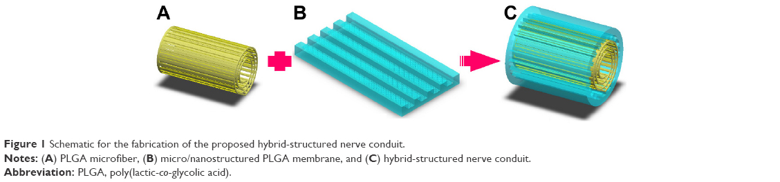 | Figure 1 Schematic for the fabrication of the proposed hybrid-structured nerve conduit. |
Microfiber fabrication
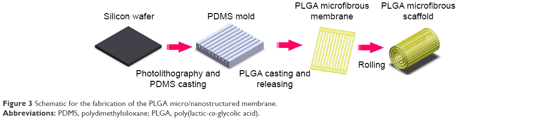
To repeatedly fabricate microfibrous membranes, we created a polydimethylsiloxane (PDMS) master mold by sequential photolithography and PDMS casting. We then used the PDMS master mold for PLGA casting to repeatedly produce microfibers.
Figure 2 shows the PLGA microfibrous membrane fabrication procedure. First, we spin-coated SU-8 2050 (Micro Chem, Westborough, MA, USA) negative photoresist to a suitable thickness on a cleaned silicon wafer substrate. After exposure to a mask with a designed pattern and developing, we obtained a replica mold of solid SU-8 2025. We then dripped a PDMS (Dow Corning, Midland, MI, USA) solution onto the SU-8 2025 replica mold, and placed it in a vacuum oven at 50°C for 12 h. We then detached the PDMS film from the replica mold and obtained a PDMS master mold with two line widths (20 and 30 μm), line spacing of 135 μm, thickness of 140 μm, and length of 9.5 mm. Next, we prepared a PLGA 85/15 (Green Square, Taoyuan, Taiwan) solution by dissolving PLGA powder in acetone (ECHO Chemical, Miaoli, Taiwan) in a 1:5 w/w ratio, gently spread it onto the PDMS replica mold, and placed the mold in a vacuum oven at 60°C for 2 min. We then scraped off any excess PLGA on the mold surface. After acetone volatilization, we performed demolding to obtain a PLGA microfiber membrane, which we then rolled into a bundle with a diameter of around 1.5–2.0 mm.
 | Figure 2 Schematic for the fabrication of the PLGA microfibrous membrane. |
Micro/nanostructured membrane fabrication
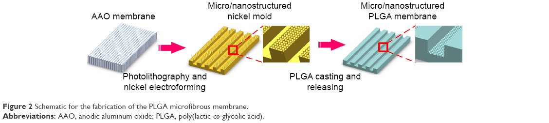
To repeatedly fabricate micro/nanostructured membranes, we created a nickel master mold by electroforming using a barrier-layer surface template of anodic aluminum oxide (AAO) film. We then used the nickel master mold for PLGA casting to repeatedly produce micro/nanostructured membranes. We used a nickel master mold rather than a conventional PDMS master mold because nanostructures cannot be easily transferred to a PDMS substrate. The PLGA micro/nanostructured membrane fabrication procedure is shown in Figure 3, and we describe the sequential fabrication processes below.
 | Figure 3 Schematic for the fabrication of the PLGA micro/nanostructured membrane. |
AAO film fabrication
We prepared the AAO film using a well-known anodizing process,25 which can be briefly summarized as follows. First, we cleaned and electropolished the aluminum foil before anodization. To produce the AAO film, we anodized the polished aluminum foil in a 0.3 M phosphoric acid solution under an applied voltage of 90 V at 0°C for 2 h. We then dissolved the remaining aluminum beneath the barrier layer in an aqueous CuCl2-HCl solution to obtain a highly ordered array of nanohemispheres.
Photolithographic processing
We spin-coated AZ1518 (Merck, Darmstadt Germany) positive photoresist to a suitable thickness on the barrier-layer surface of the fabricated AAO film. After exposing the surface to a mask with a designed pattern and developing it (using 2.38% tetramethylammonium hydroxide), we obtained a patterned AAO barrier-layer surface.
Electroforming
We conducted electroforming using a patterned barrier layer as the template to produce a micro/nanohybrid-structured nickel mold.26 We briefly describe the electroforming process below. We sputtered a 30-nm gold thin film onto the template surface as the conductive layer. Next, we carried out electroforming in a nickel sulfamate tetrahydrate solution at 55°C at a current density of 0.03 A for 1 h, followed by 0.035 A for 4.5 h. Finally, we removed the AAO template from the formed Ni mold using 0.25 M NaOH solution.
PLGA casting
We casted a PLGA (85/15) solution onto the nickel replica mold and then detached the PLGA micro/nanostructured membrane from the nickel mold after acetone volatilization.
Conduit assembly
We assembled the proposed hybrid-structured conduit by wrapping the microfibrous roll inside the micro/nanostructured membrane using PLGA solution as the adhesive.
Membrane characterization
To observe the morphologies of the fabricated samples, we used a field emission scanning electron microscope (SEM) (JSM-6700F; JEOL Co., Tokyo, Japan), an atomic force microscope (AFM) (DI 3100; Veeco Instruments Inc., Plainview, NY, USA), and an optical microscope (OM).
We estimated the degradation rate of the fabricated membranes according to the following formula:
|
|
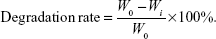
We immersed a sample with an original weight of W0 into the culture medium for 7 and 21 days. Then, we took the sample out of the culture medium and removed the absorbed culture medium. We then cleaned the sample using phosphate-buffered saline (PBS), dried it, and then weighed it. Wi denotes the dry weight of the sample after being immersed in culture medium for 7 or 21 days.
Cell culture
In our cell culture experiments, we used immortalized neuron progenitor cells KT 98.27 We placed the fabricated conduit in a six-well plate and sterilized it for 24 h with ultraviolet light. Then, we injected the cells with a concentration of 20,000 cells/mL into the conduit and cultured them in a Ham’s F-12 Nutrient Mixture (F12) (Thermo Fisher Scientific, Waltham, MA, USA) containing 10% fetal bovine serum (GIBCO) and 1% antibiotic-antimycotic (GIBCO) in an incubator at 37°C and 5% CO2. We renewed the medium every 2-3 days. The cell concentration on the flat micro/nanostructured membrane was 8,000 cells/mL.
Cell observation
Fluorescence staining
After culturing for 3 days, we fixed the cultured cells with 4% formaldehyde (Sigma-Aldrich, Taiwan) at 4°C for 30 min. After washing them with PBS, we perforated the cultured cells with 0.1% Triton X-100 (Sigma-Aldrich, St Louis, MO, USA) at room temperature for 15 min. We blocked nonspecific binding sites using 1% goat serum albumin at room temperature for 1 h. Then, we treated the cultured cells with antitubulin antibody (EMD Millipore, Etobicoke, ON, Canada) (1:500) overnight, with Alexa Fluor® 488 (Thermo Fisher Scientific) (1:300) for 1 h, and 4′,6-diamidino-2-phenylindole (DAPI; Sigma-Aldrich) (1:2,500) for 20 min. After each step, we washed the cells three times with PBS. We used a fluorescence microscope (Leica, Wetzlar, Germany) to observe the cell morphology, and used ImageJ and OrientationJ software to estimate cell length and growth direction, respectively. We then used antitubulin antibody and DAPI to stain the neuron-specific β-tubulin III and the nucleus, respectively.
Cell migration rate estimation
The Cyto-ID™ Red Long-Term Cell Tracer Kit (ENZO Life Sciences, Taipei, Taiwan) was used to label a red fluorescent dye containing hydrophobic aliphatic chains into the cell membrane’s lipid bilayer for tracking cell migration, because PLGA is a nontransparent material. In brief, cells were collected from the culture flask and the suspended cells were stained with cell tracker dye for 5 min, according to the user guide. After centrifuging to remove excess dye, the cells were resuspended in culture medium. Before seeding the cells, nine grids with an area of 1 cm2 were marked in the bottom of a 10 cm2 cell culture dish. Then, the samples got stuck in the bottom of the dish and aligned with the grids. A concentration of 8,000 cells/well of the suspended cell solution was added to the flat, micro/nano, and microfibrous scaffold, respectively. After incubation for 24 h, an inverted fluorescence microscope (Leica) was used to record cell migration image for 24 h. The ImageJ software was applied to measure the distance of cell migration.
Cell proliferation assay
We used the Cell Proliferation Assay Kit WST-1 (BioVision, Milpitas, CA, USA) to investigate the cell proliferation and prepared WST-1 reagent in a 1:10 ratio (v/v) with the cultured medium, as per the instructions in the user manual. After completing the culture process, we added the prepared WST-1 reagent into each well of a 96-well culture plate, and then incubated the plate for 4 h. Next, we transferred 100 μL of culture supernatant from each well into an enzyme-linked immunosorbent assay (ELISA) plate and determined the absorbance of each sample using an ELISA reader at a wavelength of 405 nm. We then cultured cells with a concentration of 8×10³ cells/well in a 24-well culture plate as the control.
Paraffin-embedded section and staining
We fixed the cultured cells with a 4% formaldehyde (Sigma-Aldrich) at 4°C for 30 min, dehydrated the samples using a tissue automatic dryer (Thermo Shandon Inc, Pittsburgh, PA, USA), and then embedded them in paraffin using a paraffin embedding system (EG 1150H; Leica). Then, we cut the paraffin-embedded samples into 5–15 μm thick tissue sections using a rotary microtome (RM-2145; Leica). We then floated the sections in a 55°C water bath and dried them at 32°C for 16 h. Finally, we stained the samples using hematoxylin and eosin and examined them with an OM (BX51; Olympus, Tokyo, Japan).
Statistics
We used the one-way analysis of variance test (SAS 9.4 software; SAS Institute, Taipei, Taiwan) for statistical analysis and noted that a P-value <0.01 indicates a significant difference.
Results
Conduit fabrication results
Microfiber fabrication results
Figure 4 shows an OM image of the PDMS master mold (Figure 4A) and an SEM image of a PLGA microfiber before being rolled into a bundle (Figure 4B). The designed dimensions were successfully transferred to the PDMS master mold and the fabricated PLGA microfiber.
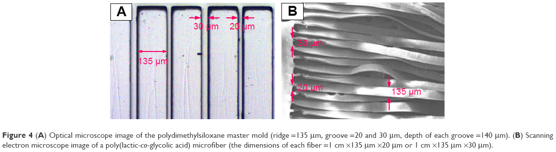 | Figure 4 (A) Optical microscope image of the polydimethylsiloxane master mold (ridge =135 μm, groove =20 and 30 μm, depth of each groove =140 μm). (B) Scanning electron microscope image of a poly(lactic-co-glycolic acid) microfiber (the dimensions of each fiber =1 cm ×135 μm ×20 μm or 1 cm ×135 μm ×30 μm). |
Figure 5 shows OM images of PLGA microfibers in the original stage (Figure 5A), and after 3 days (Figure 5B) and 14 days of degradation (Figure 5C). The fabricated microfiber was too small to examine its degradation using Equation (1). The OM image in Figure 5B shows that the PLGA microfibers had retained their original structure after 3 days of degradation. A portion of the microfibers was still connected to both ends of the structure (Figure 5C).
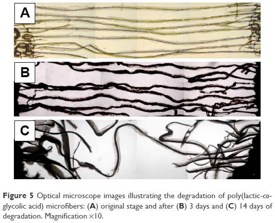 | Figure 5 Optical microscope images illustrating the degradation of poly(lactic-co-glycolic acid) microfibers: (A) original stage and after (B) 3 days and (C) 14 days of degradation. Magnification ×10. |
Micro/nanostructured membrane fabrication results
We used an OM and an AFM to characterize the nickel master mold and the fabricated micro/nanostructured membranes, respectively. Figure 6A, C shows OM images of the nickel master mold and a fabricated micro/nanostructured membrane, respectively. Figure 6B, D shows SEM images of the mold and a fabricated membrane, respectively. Figure 6C shows arrays of concave nanohemispheres on the bulges of the nickel mold. We estimated the diameters and depths of the nanohemispheres to be 210-240 and 40-60 μm, respectively. As shown in Figure 6D, the nanohemisphere arrays were reprinted into the grooves of the PLGA membrane as arrays of convex nanohemispheres. We measured the diameters and heights of the reprinted nanohemispheres to be 180-200 and 35-40 μm, respectively.
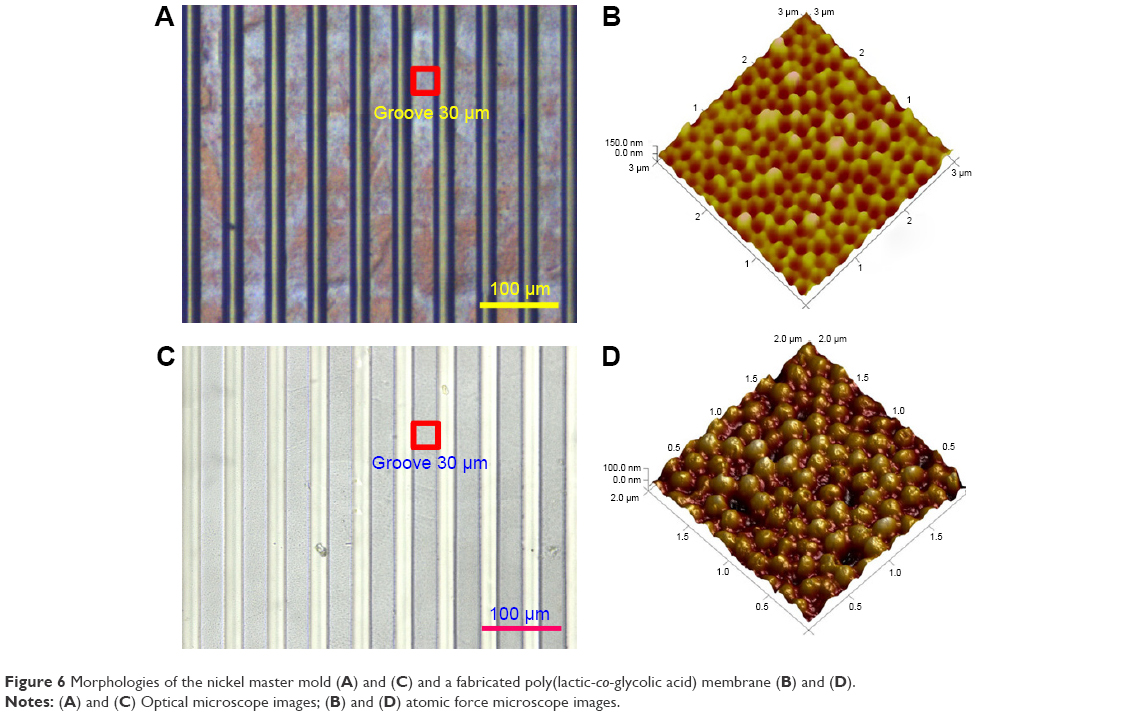 | Figure 6 Morphologies of the nickel master mold (A) and (C) and a fabricated poly(lactic-co-glycolic acid) membrane (B) and (D). |
Figure 7 shows the morphologies of the fabricated PLGA membranes after being immersed in culture medium for 0, 7, and 21 days. The images in Figure 7A–F are surface images, while those in Figure 7G–I are cross-sectional images. The OM images in Figure 7A–C show that the material gradually swelled and the dimensions of the micropatterns increased. The SEM images shown in Figure 7D–F indicate that pores were produced on the surface of the bulges. Nanostructures are clearly observed on the surface, and the cross-sectional view of the membrane shows that no pore was generated or present on day 0 (Figure 7D, G). After 7 days of degradation, the nanostructures were degraded and micropores were generated on the shallow surface (Figure 7E, H). Large micropores were displayed on the whole PLGA membrane after 21 days of degradation (Figure 7F, I). It can be observed that the micropatterns were not obviously degraded, and the thickness of the PLGA membrane did not significantly change throughout the degradation period. Using the ImageJ software, we estimated the pore coverage area after 0, 7, and 14 days of immersion to be 0.096, 0.223, and 0.381 μm2, respectively.
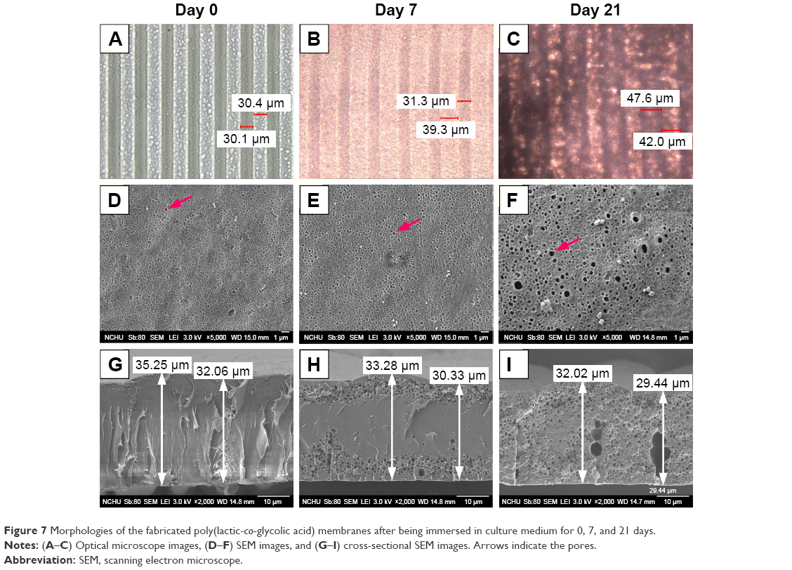 | Figure 7 Morphologies of the fabricated poly(lactic-co-glycolic acid) membranes after being immersed in culture medium for 0, 7, and 21 days. |
Conduit assembly results
Figure 8 shows a frozen section and an SEM image of a fabricated conduit. The frozen section image in Figure 8A shows the successful assembly of the conduit. The SEM image of the hybrid-structured membrane in Figure 8B confirms that the micro/nanohybrid pattern remained on the inner wall of the membrane.
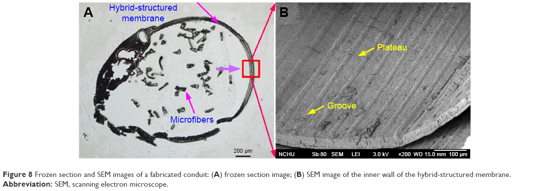 | Figure 8 Frozen section and SEM images of a fabricated conduit: (A) frozen section image; (B) SEM image of the inner wall of the hybrid-structured membrane. |
Cell culture results
Cell morphologies
Class III β-tubulin is a microtubule element found exclusively in neurons, where it accumulates as a consequence of nerve growth factor-stimulated neurite outgrowth.28 Figure 9 shows the cell morphologies stained with β-tubulin specific marker on a flat PLGA, a micro/nanostructured and a microfibrous membrane after 3 days of culture. Cells cultured on a flat PLGA stretched randomly (Figure 9A) and presented spindle or branching triangle-like morphology. Cells cultured on the micro/nanostructured membrane (Figure 9B) aligned with the microstructures (white arrow indicates the orientation of microstructures) and cells crossing over from one ridge to a neighboring ridge were observed (yellow arrows). Cells cultured on the microfiber membrane grew along a certain ridge without crossing over to a neighboring ridge (Figure 9C). Figure 9D compares the length of cells cultured on different materials. Cells cultured on the flat PLGA and the micro/nanostructured membrane were relatively longer and were significantly different from those cultured on the microfiber membranes (P<0.001). Cells cultured on the microfibers were the shortest because of their denser attachment to the material. To further investigate the growth direction of the cells, we defined the direction along the microstructure to be 0° and estimated the distribution ratio of cells within ±10° and ±45°, respectively. As listed in Table 1, 40% of the cells cultured on the micro/nanostructured membrane grew within ±10°, while 90% of the cells grew within ±45°. These results indicated that the micro/nanostructured membrane has a better guiding ability than the flat PLGA. To prepare a nerve conduit that can effectively guide nerve cells in both the center and the inner wall of a conduit, we suggest that a micro/nanostructured membrane is more suitable than a flat PLGA as the conduit shell material.
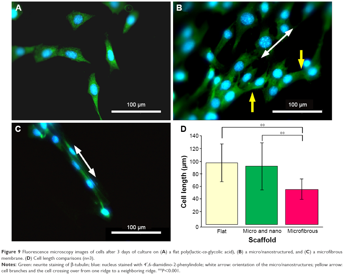 | Figure 9 Fluorescence microscopy images of cells after 3 days of culture on (A) a flat poly(lactic-co-glycolic acid), (B) a micro/nanostructured, and (C) a microfibrous membrane. (D) Cell length comparisons (n=3). |
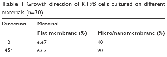 | Table 1 Growth direction of KT98 cells cultured on different materials (n=30) |
Cell migration and proliferation
In Figure 10, we compare the cell migration and proliferation rates of cells cultured on the different materials. Figure 10A compares the cell migration rates, which we estimated using fluorescence microscopy to observe cell migration. The results indicate that cells cultured on a flat PLGA migrated relatively more slowly (6.68 μm/h) than the microfibers (10.71 μm/h) and the micro/nanostructured membrane (10.77 μm/h). Based on these results, the cell migration rate in the micro/nanomembrane and the microfibrous PLGA was increased 1.6 times when compared with that of the flat PLGA, further confirming that both the microfibers and the micro/nanostructured membrane provide neural cells with a better migration environment.
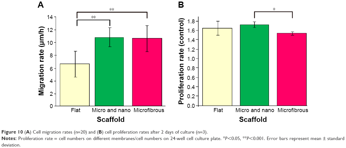 | Figure 10 (A) Cell migration rates (n=20) and (B) cell proliferation rates after 2 days of culture (n=3). |
Figure 10B presents the proliferation rates of cells cultured on different materials. The proliferation rates of cells cultured on the flat PLGA and the micro/nanostructured membrane were about the same (about a 1.6-fold increase compared with the control group [24-well cell culture plate]), whereas the proliferation rate of cells on the microfibers was relatively lower than that on the flat PLGA and the micro/nanostructured membrane (1.5 times that of the control group). This can be attributed to the relatively smaller attachable area on the microfibers. The cell density was found to be highly confluent after 2 days of culturing on PLGA fibers (Figure 9C). These results indicate that our designed structures can provide a good microenvironment to enhance nerve cell migration velocity and proliferation, when compared with a flat PLGA.
Cell behavior in the conduit
After 3 days of culturing, we used the frozen section technique to examine cell behavior in the proposed nerve conduit. Figure 11 shows frozen section images of the cells cultured on the nerve conduit for 3 days. The interior of the nerve conduit was filled with cells (Figure 11A, B), and the packed microfibers were also surrounded by cells (Figure 11C, D). As indicated by the arrows, cells adhered and aligned along with the parallel microfibers of the microfibrous bundle and the micro/nanohybrid structure of the shell membrane. These cell culture results from the conduit culture reveal that the micro/nanohybrid and microfibrous structures that form the proposed nerve conduit can maintain their shapes. We can conclude that the proposed hybrid-structured conduit has a high capability to guide nerve cells and promote cell migration.
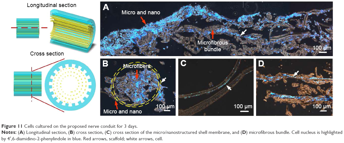 | Figure 11 Cells cultured on the proposed nerve conduit for 3 days. |
Discussion
Nerve conduits with micropatterns using different biomaterials have been increasingly developed to reconnect large gaps on fractured nerve fibers. We further proposed a nerve guidance conduit consisting of a hybrid structure of a microfibrous PLGA bundle (30 μm width of each fiber) wrapped within a micro/nanostructured PLGA membrane to supplement the lower neurite guidance ability and the nerve regrowth in the central part of a conduit. For the nerve conduit shell, we chose the micro/nanostructured PLGA membrane with a 30/30 μm microgroove pattern (width =30 μm, spacing =30 μm), where each microgroove is filled with an array of nanohemispheres with diameter and height of 180-200 and 35-40 μm, respectively. The average degradation rates of the micro/nanostructured membrane were 0.57% and 0.15% after immersing in culture medium for 7 and 21 days, respectively. During degradation, the nanospheres in each groove gradually became smooth and pores were simultaneously generated within the membrane. During degradation, pores only appeared on the shallow membrane and less on the surface on the 7th day. The pores were fully displayed throughout the membrane on the 21st day. This phenomenon can be attributed to the degradation kinetics of PLGA, which undergoes bulk degradation. A large number of acidic substances, from PLGA hydrolysis, accumulate in the middle of the PLGA membrane, leading to a high degradation rate observed in the center than on the PLGA surface, as the medium neutralizes the acidic substances on the PLGA surface. We designed the microfibrous PLGA bundle to avoid the shrinkage of nerves that occurs in a hollow conduit. For the microfibrous PLGA degradation, it was observed that the degrading period was shorter than for the PLGA membrane. The fibers were dramatically deformed and broke on the 3rd and 14th day, because they were too thin to resist the acidic environment. These results are consistent with previously published studies.29,30
PLGA is an artificial copolymer that is synthesized using lactic acid and glycolic acid monomers via ring opening polymerization. PLGA is also a Food and Drug Administration-approved material used in drug delivery. It possesses bioinertness and good mechanical strength and can be easily fabricated into various polymeric devices, such as microspheres, microcapsules, nanoparticles, pellets, implants, and films, for medical use.31 In this study, the proliferation rate of cells cultured on a flat, micro/nanostructured, and microfibrous PLGA is greater than 1.5 times the proliferation rate of cells cultured on a 24-well culture plate after 2 days of culture. It was demonstrated that PLGA did not affect cell growth but promoted cell proliferation.
It has been reported that a nerve conduit with micro- or nanopatterns can guide neurite growth and promote cell migration.32–34 Li et al fabricated a series of topographical screens to investigate the physical neural-guidance cues. Hippocampal neurons cultured on anisotropic topographies (linear, circular, angular gratings, triangular, and rectangular) expressed better axonal elongation and dendritic extensions in contrast to those cultured on the isotropic topographies (dots, grids, and squares). However, cells cultured on planar substrates presented dendritic branching over the microscale features.35 Our previous study demonstrated that the micro/nanohybrid structures with 30/30 μm microgroove pattern (nanostructures in grooves) exhibited good nerve cell guidance and had less branching than the pure micropatterns.36 Our experimental results on cell guiding ability of the proposed micro/nanostructured PLGA membrane in this study are consistent with previous studies. However, neurite elongation was not so obvious, which can be attributed to the shifting of the cell orientation from a parallel to a perpendicular alignment by the nanostructures in the groove. Teixeira et al reported that the parallel alignment tendency can be interrupted when the pitch size is decreased from 4,000 to 400 nm.37
The effect of micro/nanotopography environments on cell migration is typically investigated based on cell cultured on gratings or fibers. Many cell types exhibit space-biased migration in the direction of the grating or fiber axis.38 Our orientation measurement (Table 1) and migration rate observation results (Figure 10A) indicate the occurrence of similar phenomenon. The regulatory pathway of cell migration on a two-dimensional synthetic material is a complex physiological response that can be generalized as a cycle consisting of multiple steps: polarization of the cell and extension of pseudopodia in the direction of migration, stabilization of pseudopodia by adhesion to the material, forward movement by concentration, and cell detachment at the rear.39 Class III β-tubulin is a microtube element found exclusively in neurons; it is also one of the components responsible for neurite outgrowth and cell motility. In Figure 9B, C, we can observe that much more β-tubulins were contracted on microgratings or fibers in the parallel direction in contrast to cell cultured on flat PLGA membranes. This may be an important factor of cell migration rate enhancement, because most of the protruding pseudopodia are contracted in the same direction.
Our results indicate that a nerve conduit shell using the proposed micro/nanostructured PLGA membrane can provide a better environment than a flat membrane for enhancing cell migration and proliferation in vitro. In addition, the microfibrous PLGA bundle is able to effectively guide the growth of neural cells and can induce a similar cell migration rate as that of a micro/nanostructured PLGA membrane. Therefore, the regenerated cells are able to migrate from both points of injury at a similar speed along the conduit to connect with each other, hence avoiding the shrinkage problem. We have demonstrated that the proposed hybrid-structured conduit is capable of guiding nerve cells and promoting cell migration in vitro and would find use in future clinical applications.
Conclusion
We proposed a novel conduit to address the disadvantages of the hollow-structured conduits currently used. This novel nerve guidance conduit consists of a hybrid structure of a microfibrous PLGA bundle wrapped in a micro/nanostructured membrane. Cell culture results indicate that the micro/nanostructured PLGA membrane can provide a better environment than a flat membrane for enhancing the migration and proliferation of cultured cells. We also demonstrated the ability of the microfibrous PLGA bundle to effectively guide the growth of neural cells at a similar migration rate as that of a micro/nanostructured PLGA membrane. As such, it is capable of preventing the shrinkage problem of hollow-structured conduits. Furthermore, our conduit cell culture results demonstrate that the micro/nanohybrid and microfibrous structures maintain their shapes. The proposed hybrid-structured conduit demonstrates a high capability for guiding nerve cells and promoting cell migration in vitro and provides an opportunity for use in future clinical applications.
Acknowledgment
The authors would like to offer their thanks to the Ministry of Science and Technology of Taiwan under grant number MOST-103-2221-E-005-046-MY2 for their financial support of this research.
Disclosure
The authors report no conflicts of interest in this work.
References
Vasita R, Katti DS. Nanofibers and their applications in tissue engineering. Int J Nanomedicine. 2006;1(1):15–30. | ||
Nyyssönen T, Saarikoski H, Kaukonen JP, Lüthje P, Hakovirta H. Simple end-to-end suture versus augmented repair in acute Achilles tendon ruptures: a retrospective comparison in 98 patients. Acta Orthop Scand. 2003;74(2):206–208. | ||
Teboul F, Kakkar R, Ameur N, Beaulieu JY, Oberlin C. Transfer of fascicles from the ulnar nerve to the nerve to the biceps in the treatment of upper brachial plexus palsy. J Bone Joint Surg Am. 2004;86(7):1485–1490. | ||
Terzis JK, Tzafetta K. The “babysitter” procedure: minihypoglossal to facial nerve transfer and cross-facial nerve grafting. Plast Reconstr Surg. 2009;123(3):865–876. | ||
Kim YT, Haftel VK, Kumar S, Bellamkonda RV. The role of aligned polymer fiber-based constructs in the bridging of long peripheral nerve gaps. Biomaterials. 2008;29(21):3117–3127. | ||
Muheremu A, Ao Q. Past, present, and future of nerve conduits in the treatment of peripheral nerve injury. Biomed Res Int. 2015;215:237507. | ||
Griffin MF, Malahias M, Hindocha S, Wasim SK. Peripheral nerve injury: principles for repair and regeneration. Open Orthop J. 2014;8:199–203. | ||
Nectow AR, Marra KG, Kaplan DL. Biomaterials for the development of peripheral nerve guidance conduits. Tissue Eng Part Rev. 2012;18(1):40–50. | ||
Ribeiro-Resende VT, Koenig B, Nichterwitz S, Oberhoffner S, Schlosshauer B. Strategies for inducing the formation of bands of Büngner in peripheral nerve regeneration. Biomaterials. 2009;30(29):5251–5259. | ||
Daly W, Yao L, Zeugolis D, Windebank A, Pandit A. A biomaterials approach to peripheral nerve regeneration: bridging the peripheral nerve gap and enhancing functional recovery. J R Soc Interface. 2012;9(67):202–221. | ||
Shin RH, Friedrich PF, Crum BA, Bishop AT, Shin AY. Treatment of a segmental nerve defect in the rat with use of bioabsorbable synthetic nerve conduits: a comparison of commercially available conduits. J Bone Joint Surg Am. 2009;91(9):2194–2204. | ||
Summa PG, Kingham PJ, Campisi CC, Raffoul W, Kalbermatten DF. Collagen (NeuraGen®) nerve conduits and stem cells for peripheral nerve gap repair. Neurosci Lett. 2014;572:26–31. | ||
Ngo TTB, Waggoner PJ, Romero AA, Nelson KD, Eberhart RC, Smith GM. Poly(L-lactide) microfilaments enhance peripheral nerve regeneration across extended nerve lesions. J Neurosci Res. 2003;72(2):227–238. | ||
Huang W, Begum R, Barber T, et al. Regenerative potential of silk conduits in repair of peripheral nerve injury in adult rats. Biomaterials. 2012;33(1):59–71. | ||
Yucel D, Kose GT, Hasirci V. Polyester based nerve guidance conduit design. Biomaterials. 2010;31(7):1596–1603. | ||
Yucel D, Kose GT, Hasirci V. Tissue engineered, guided nerve tube consisting of aligned neural stem cells and astrocytes. Biomacromolecules. 2010;11(12):3584–3591. | ||
Luis AL, Rodrigues JM, Amado S, et al. PLGA 90/10 and caprolactone biodegradable nerve guides for the reconstruction of the rat sciatic nerve. Microsurgery. 2007;27(2):125–137. | ||
Letourneau PC. Cell-to-substratum adhesion and guidance of axonal elongation. Dev Biol. 1975;44(1):92–101. | ||
Goldner JS, Bruder JM, Li G, Gazzola D, Hoffman-Kim D. Neurite bridging across micropatterned grooves. Biomaterials. 2006;27(3):460–472. | ||
Li G, Zhao X, Zhao W, et al. Porous chitosan scaffolds with surface micropatterning and inner porosity and their effects on Schwann cells. Biomaterials. 2014;35(30):8503–8513. | ||
Bremus-Koebberling EA, Beckemper S, Koch B, Gillner A. Nano structures via laser interference patterning for guided cell growth of neuronal cells. J Laser Appl. 2012;24(4):042013. | ||
Bechara S, Popat KC. Micro-patterned nanowire surfaces encourage directional neural progenitor cell adhesion and proliferation. J Biomed Nanotechnol. 2013;9(10):1698–1706. | ||
Nam Y, Wheeler BC, Heuschkel MO. Neural recording and stimulation of dissociated hippocampal cultures using microfabricated three-dimensional tip electrode array. J Neurosci Methods. 2006;155(2):296–299. | ||
Jiang X, Bruzewicz DA, Wong AP, Piel M, Whitesides GM. Directing cell migration with asymmetric micropatterns. Proc Natl Acad Sci U S A. 2005;102(4):975–978. | ||
Tsai JJ, Bau IJ, Chen HT, Lin YT, Wang GJ. A novel nanostructured biosensor for the detection of the dust mite antigen Der p2. Int J Nanomedicine. 2011;6:1201–1208. | ||
Chung IC, Li CW, Wang GJ. The influence of different nanostructured scaffolds on fibroblast growth. Sci Technol Adv Mater. 2013;14(4):044401. | ||
Hsu YC, Lee DC, Chen SL, et al. Brain-specific 1B promoter of FGF1 gene facilitates the isolation of neural stem/progenitor cells with self-renewal and multipotent capacities. Dev Dyn. 2009;238(2):302–314. | ||
Joshi HC, Cleveland DW. Differential utilization of beta-tubulin isotypes in differentiating neurites. J Cell Biol. 1989;109(2):663–673. | ||
Vey E, Rodger C, Meehan L, et al. The impact of chemical composition on the degradation kinetics of poly (lactic-co-glycolic) acid copolymers cast films in phosphate buffer solution. Polym Degrad Stab. 2012;97(3):358–365. | ||
Shirazia RN, Aldabbagh F, Erxleben A, Rochev Y, McHugh P. Nanomechanical properties of poly (lactic-co-glycolic) acid film during degradation. Acta Biomater. 2014;10(11):4695–4703. | ||
Jain RA. The manufacturing techniques of various drug loaded biodegradable poly(lactide-co-glycolide) (PLGA) devices. Biomaterials. 2000;21(23):2475–2490. | ||
Tuft BW, Li S, Xu L, et al. Photopolymerized microfeatures for directed spiral ganglion neurite and Schwann cell growth. Biomaterials. 2013;34(1):42–54. | ||
Nagamine K, Hirata T, Okamoto K, Abe Y, Kaji H, Nishizawa M. Portable micropatterns of neuronal cells supported by thin hydrogel films. ACS Biomater Sci Eng. 2015;1:329–334. | ||
Guo Z, Hu K, Sun J, et al. Fabrication of hydrogel with cell adhesive micropatterns for mimicking the oriented tumor-associated extracellular matrix. ACS Appl Mater Interfaces. 2014;6(14):10963–10968. | ||
Li W, Tang QY, Jadhav AD, et al. Large-scale topographical screen for investigation of physical neural-guidance cues. Sci Rep. 2015;5:8644. | ||
Lin YT, Li CW, Wang GJ. The micro/nanohybrid structures enhancing B35 cell guidance on chitosan. J Nanotechnol Eng Med. 2015;6(3):031005. | ||
Teixeira AI, Abrams GA, Bertics PJ, Murphy CJ, Nealey PF. Epithelial contact guidance on well-defined micro- and nanostructured substrates. J Cell Sci. 2003;116(Pt 10):1881–1892. | ||
Flemming RG, Murphy CJ, Abrams GA, Goodman SL, Nealey PF. Effects of synthetic micro- and nano-structured surfaces on cell behavior. Biomaterials. 1999;20(6):573–588. | ||
Lutolf MP, Hubbell JA. Synthetic biomaterials as instructive extracellular microenvironments for morphogenesis in tissue engineering. Nat Biotechnol. 2005;23(1):47–55. |
 © 2017 The Author(s). This work is published and licensed by Dove Medical Press Limited. The full terms of this license are available at https://www.dovepress.com/terms.php and incorporate the Creative Commons Attribution - Non Commercial (unported, v3.0) License.
By accessing the work you hereby accept the Terms. Non-commercial uses of the work are permitted without any further permission from Dove Medical Press Limited, provided the work is properly attributed. For permission for commercial use of this work, please see paragraphs 4.2 and 5 of our Terms.
© 2017 The Author(s). This work is published and licensed by Dove Medical Press Limited. The full terms of this license are available at https://www.dovepress.com/terms.php and incorporate the Creative Commons Attribution - Non Commercial (unported, v3.0) License.
By accessing the work you hereby accept the Terms. Non-commercial uses of the work are permitted without any further permission from Dove Medical Press Limited, provided the work is properly attributed. For permission for commercial use of this work, please see paragraphs 4.2 and 5 of our Terms.