")
Back to Journals » International Journal of Nanomedicine » Volume 10 » Issue 1
Magnetic particle imaging: current developments and future directions
Authors Panagiotopoulos N, Duschka RL, Ahlborg M, Bringout G, Debbeler C, Graeser M, Kaethner C, Lüdtke-Buzug K, Medimagh H, Stelzner J, Buzug TM , Barkhausen J , Vogt F, Haegele J
Received 31 July 2014
Accepted for publication 27 October 2014
Published 22 April 2015 Volume 2015:10(1) Pages 3097—3114
DOI https://doi.org/10.2147/IJN.S70488
Checked for plagiarism Yes
Review by Single anonymous peer review
Peer reviewer comments 3
Editor who approved publication: Professor Lei Yang
Nikolaos Panagiotopoulos,1 Robert L Duschka,1 Mandy Ahlborg,2 Gael Bringout,2 Christina Debbeler,2 Matthias Graeser,2 Christian Kaethner,2 Kerstin Lüdtke-Buzug,2 Hanne Medimagh,2 Jan Stelzner,2 Thorsten M Buzug,2 Jörg Barkhausen,1 Florian M Vogt,1 Julian Haegele1
1Clinic for Radiology and Nuclear Medicine, University Hospital Schleswig Holstein, Campus Lübeck, 2Institute of Medical Engineering, University of Lübeck, Lübeck, Germany
Abstract: Magnetic particle imaging (MPI) is a novel imaging method that was first proposed by Gleich and Weizenecker in 2005. Applying static and dynamic magnetic fields, MPI exploits the unique characteristics of superparamagnetic iron oxide nanoparticles (SPIONs). The SPIONs’ response allows a three-dimensional visualization of their distribution in space with a superb contrast, a very high temporal and good spatial resolution. Essentially, it is the SPIONs’ superparamagnetic characteristics, the fact that they are magnetically saturable, and the harmonic composition of the SPIONs’ response that make MPI possible at all. As SPIONs are the essential element of MPI, the development of customized nanoparticles is pursued with the greatest effort by many groups. Their objective is the creation of a SPION or a conglomerate of particles that will feature a much higher MPI performance than nanoparticles currently available commercially. A particle’s MPI performance and suitability is characterized by parameters such as the strength of its MPI signal, its biocompatibility, or its pharmacokinetics. Some of the most important adjuster bolts to tune them are the particles’ iron core and hydrodynamic diameter, their anisotropy, the composition of the particles’ suspension, and their coating. As a three-dimensional, real-time imaging modality that is free of ionizing radiation, MPI appears ideally suited for applications such as vascular imaging and interventions as well as cellular and targeted imaging. A number of different theories and technical approaches on the way to the actual implementation of the basic concept of MPI have been seen in the last few years. Research groups around the world are working on different scanner geometries, from closed bore systems to single-sided scanners, and use reconstruction methods that are either based on actual calibration measurements or on theoretical models. This review aims at giving an overview of current developments and future directions in MPI about a decade after its first appearance.
Keywords: magnetic particle imaging, superparamagnetic iron oxide nanoparticles, magnetic particle spectrometer, peripheral nerve stimulation, cardiovascular interventions
Introduction
There is one prefix that has opened up innumerable new research fields and promises amazing new possibilities. This prefix is “nano,” meaning a billionth of the unit it is put before, and, in the case of a nanometer, it means just a few atoms wide. Today, particles of these dimensions, so called nanoparticles, play a key role in many fields of our daily lives. Their particular properties are utilized from plant construction to medicine. Magnetic particle imaging (MPI) is one result of this development.
It was more than a decade ago, in 2001, that the concept of MPI – built around superparamagnetic iron oxide nanoparticles (SPIONs) – was conceived by Gleich at the Philips Research Laboratory in Hamburg, Germany. MPI takes advantage of the response of SPIONs to an oscillating magnetic field to determine their spatial distribution and local concentration. In 2005, Gleich and Weizenecker wrote a pivotal paper in which they reported the first MPI images and proved the feasibility of this method.1,2 This was the starting signal for a development that was and still is led by numerous research groups all over the globe.
MPI is the first medical application in which nanoparticles are not just supportive contrast agents, as in magnetic resonance imaging (MRI), but the only source for signal and thus the only visualized element. That is why the used SPIONs are referred to as tracers rather than contrast agents. One crucial characteristic of SPIONs in comparison with protons in a field of 1.5 T – the main source of the MRI-signal – is their 108 times higher magnetization and their 104 times faster relaxation.3 These two characteristic variables can be translated into the above mentioned outstanding temporal resolution and into a higher signal-to-noise-ratio (SNR). Due to the fact that tissue is diamagnetic, it does not generate any interfering signal, leading to an image of the tracer distribution that features a superb contrast.4–6 Consequently, MPI does not visualize anatomical structures if they are not labeled by the tracer.
What sets MPI apart from medical imaging modalities currently in use is its inherent combination of capabilities. MPI promises a very high temporal resolution with high acquisition rates of up to 40 volumes per second as well as a high spatial resolution of up to about 1 mm.1,7 Since the strength of the MPI signal is proportional to the concentration of nanoparticle tracers in the field of view (FOV), quantitative data could be acquired. Furthermore, MPI is sensitive, works without ionizing radiation, and offers a three-dimensional image of the SPIONs’ distribution with a great contrast.2,8
This unique combination predestines MPI for a variety of medical applications, eg, cardiovascular diagnostic and interventional procedures as well as cell labelling and tracking.
In this review, an introduction into the basic principles of MPI will be provided – from the signal generation and acquisition over the encoding of the signal to the final reconstruction of an image. The SPIONs, the centerpiece of MPI, are presented together with an update on MPI tracers in development. Furthermore, the actual implementation of the method with an overview of currently available scanners and preclinical demonstrators is offered. In the context of upscaling the preclinical systems to commercially available clinical systems, some safety issues will be highlighted. A presentation of prospective medical applications that exploit the unique potential of MPI will conclude this review.
For a more extensive insight into the physics and chemistry of MPI and SPIONs, we would like to refer to more comprehensive writings, eg, Knopp and Buzug2 as well as Gleich.9
Magnetic particle image: the basic concept
Signal generation and acquisition
MPI exploits the special characteristics and the response of SPIONs when exposed to certain magnetic fields generated by a complex coil topology in the MPI scanner. The tracer’s response is picked up by receiving coils and used as the fundamental signal for the three-dimensional visualization of the tracer’s distribution in space.
By applying a direct and an alternating current to these coils, static and varying magnetic fields are generated, respectively (Figure 1).
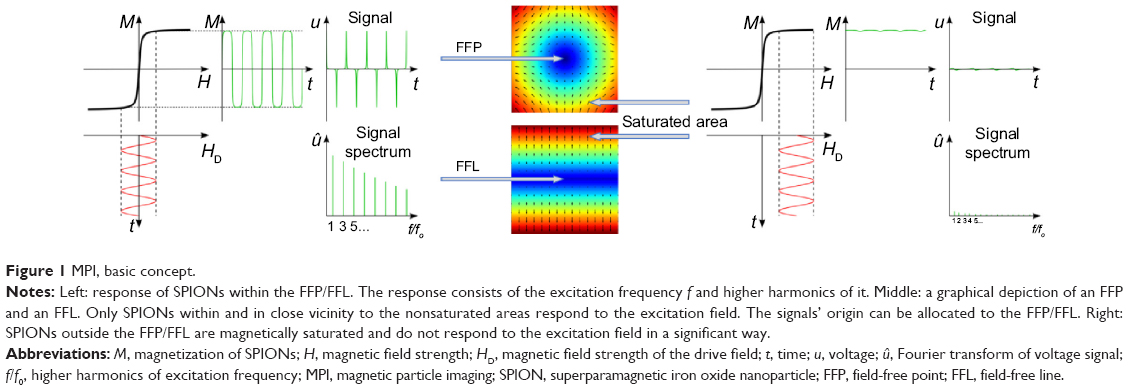 | Figure 1 MPI, basic concept. |
The varying magnetic fields featuring specific frequencies f and high enough amplitudes A are used to excite the SPIONs, ie, change their magnetization direction. The applied fields are therefore known as excitation fields. As the SPIONs’ magnetization curve is nonlinear, the Fourier transform of their magnetization over time, M(t), includes the excitation frequency as well as higher harmonics of this frequency.1 The presence of these higher harmonics allows a separation of the signal originating from the tracer and the one coming from the scanner’s excitation field. The response of the SPIONs is picked up by dedicated receiving coils. The changing magnetization of the superparamagnetic particles causes an electrical induction in the receiving coils, which represents the acquired information about the tracer material.
Spatial encoding
In a setup as described so far, the excitation of the particles would not be limited to a defined region in the imaging area, and all particles exposed to the excitation field would be excited. A possible way to narrow down the area where the particles are excited is to superimpose the excitation fields with a static magnetic gradient field (Figure 1; middle). The size of this dynamic imaging region and, consequently, the achievable resolution is strongly dependent on the applied gradient strength G for the x, y, and z direction. At this point, a second important feature of the SPIONs has to be mentioned – they are magnetically saturable if exposed to magnetic fields with a high enough amplitude. Such a field, referred to as a selection field, is generated by a Maxwell-coil pair and features a magnetic field-free point (FFP).1,10–12 Due to the selection field, the SPIONs outside the FFP are magnetically saturated (Figure 1; right), and only tracer material directly in or in close vicinity to this well-defined FFP is influenced by the excitation field (Figure 1; left). An alternative encoding concept to the FFP-based approach is the use of a magnetic field-free line (FFL), which promises an increase in the sensitivity of the system.13–15
In order to acquire a signal over the whole FOV, the FFP or FFL has to be moved relatively to this area. To realize an adequate covering of the FOV in a reasonable time, specific trajectories are used as a data acquisition path.16 Figure 2 depicts four different trajectories. The movement can be realized either by a mechanical shift of the object or by additional magnetic fields. These fields, referred to as drive fields, are varying magnetic fields and enable the movement of the FFP or FFL, respectively. It should be noted that in actual implemented scanner systems, the excitation fields and the drive fields are implemented using either separate coils or the same coils.17
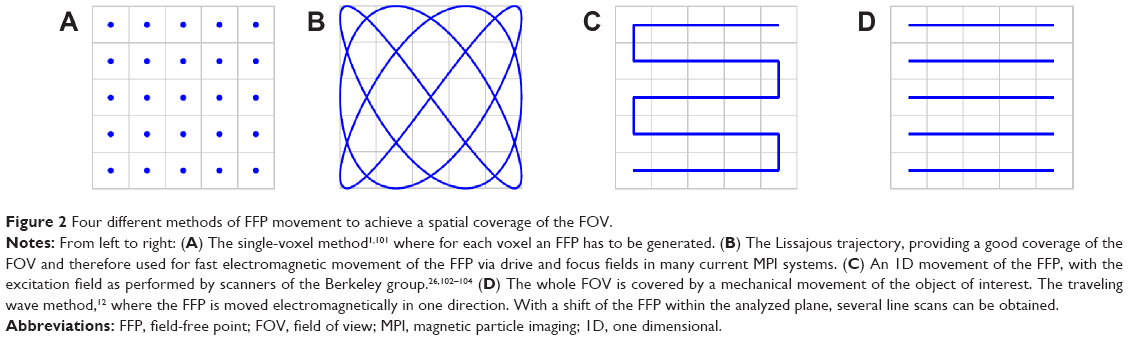 | Figure 2 Four different methods of FFP movement to achieve a spatial coverage of the FOV. |
Reconstruction principles
To reconstruct the spatial distribution of the particle concentration from the received voltage signal, an adequate image reconstruction has to be performed. In order to meet the requirements of reconstruction, which are a reasonable reconstruction effort and reconstruction time as well as a sufficient image quality, different approaches have been proposed to date.18–20 In general, it is possible to differentiate between two main methods that are used for reconstruction with current existing imaging systems. The first is a system matrix-based reconstruction that depends on a supplemental calibration scan that is performed by moving a delta-sample by robotic means,1,21,22 and the second is a direct reconstruction known as x-space MPI, which is based on some idealized assumptions.
A system matrix includes the information about the particle behavior at every position within the scanner and, therefore, represents a calibration of the system. Using the system matrix, it is possible to disassemble the signal of all particles encoded in the received signal into the individual signals of each spatial position. With the system matrix S, the receive signal, u, and the particle concentration c, it follows that Sc = u. In order to solve this system of equations, typically, an iterative solver combined with regularization typically is used to solve the minimization problem:
|
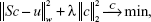
as noise and the structure of S inhibit a direct solution.19 Here, λ denotes the regularization parameter that controls the influence of the regularization. The weighting matrix W can be used to suppress entries of the system matrix with bad SNR so that entries with good SNR properties have a strong influence on the image reconstruction.
A major drawback of the system matrix based approach is the time necessary to perform the calibration measurement. One possibility to omit this tedious procedure is to use x-space reconstruction.20 The basic concept is based on assumptions regarding the particles’ behavior and the pureness of the applied magnetic fields. If these assumptions are fulfilled, a direct reconstruction of the particle concentration c is possible. A simplified formula as published in Goodwill and Connolly20 can be given by
|

where the voltage signal u(x) acquired at a known position x is normalized with the corresponding FFP velocity υFFP(x). However, the physical correct solution contains some normalization terms that do not change the information stored in c.18,20 Depending on the used imaging sequence and the scan time, this image reconstruction results in blurred images that can be post-processed with a deconvolution.6
To date, a system matrix based reconstruction has to be chosen in order to make use of the full potential of MPI in terms of real-time imaging. That is because the dedicated system matrix includes the deviations of the magnetic fields and the complex particle characteristics in the calibration and thereby allows the encoding of the information in the region of interest with a fast Lissajous trajectory. Several image reconstruction results have been published so far. The first in vivo results presented by Weizenecker et al7 as well as several other studies with dynamic images23–25 have been reconstructed with dedicated system matrices (see Figure 3).
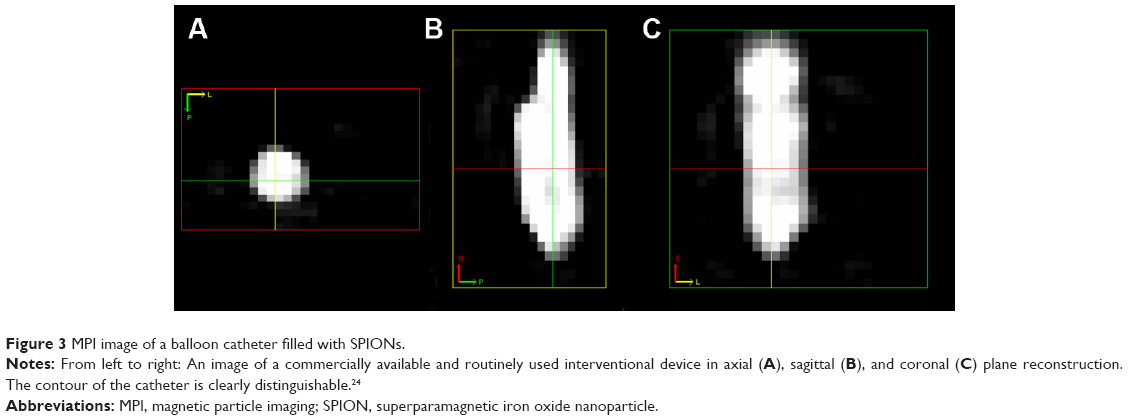 | Figure 3 MPI image of a balloon catheter filled with SPIONs. |
While image quality with x-space is equally convincing, the effort and the time for image reconstruction are much lower than for the system matrix based approach. Current image acquisition procedures take several minutes to enable a good x-space reconstruction.6,26
Magnetic particle spectrometer
A magnetic particle spectrometer (MPS), as shown in Figure 4, is in concept very similar to an MPI device. In contrast to the imaging scanner, the spatial distribution of nanoparticles is known, and only their physical characteristics are to be studied. Recent research has shown the possibility of a spectrometer to measure the particle core diameter,27 the particle hydrodynamic diameter,28 its temperature,29 and its binding status.30 As these measurements can be used to predict the imaging performance in MPI scanners, the MPS is a helpful tool in particle synthesis as well as in the development of dynamic particle models. Current developments in the signal chain have led to higher sensitivity and higher signal purity.31,32
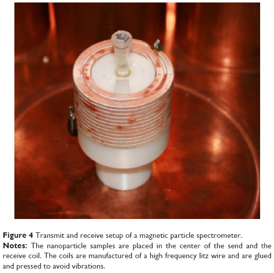 | Figure 4 Transmit and receive setup of a magnetic particle spectrometer. |
As the spatial distribution is known and the sample size seldom exceeds 20 μL, the selection field can be excluded from the signal chain. The consequences are reduced costs, smaller size, and lower complexity of the device. The field generator is optimized in terms of maximum homogeneity to suppress modeling errors due to different particle excitations. With sufficient homogeneity, the second optimization parameter is the sensitivity of the coil array. This provides a high SNR and makes it possible to measure even high-diluted samples, which can differ in their physical properties from undiluted samples. As in future in vivo applications, where the tracer will be highly diluted in the blood flow of the patient, the sensitivity of the spectrometric device is a crucial parameter.
A measurement is performed by applying a given sequence of time-varying magnetic fields to the particles and recording the particle response. Then the physical parameters are determined by fitting the physical models to this measured response. The amplitude of the particle response is proportional to the amount of particles enclosed in the measured sample. This can be used to measure the uptake of nanoparticles in a specific tissue or organs, ie, lymph nodes.33 This uptake directly corresponds to the efficacy of functionalized particles.
Superparamagnetic iron oxide nanoparticles
SPIONs are the centerpiece of MPI as its principle is based on three of the SPIONs’ characteristics. First, SPIONs are superparamagnetic. A superparamagnetic material does not show any remanent magnetization when a magnetic field used for excitation is turned off. This is due to the Brownian and Néel relaxation, which changes the magnetization direction under thermal excitation even at room temperature. Thus, the SPIONs’ magnetization follows the excitation field (see Figure 5), ie, the drive field. Second and third, as mentioned above, SPIONs exhibit a nonlinear magnetization curve and can be magnetically saturated. This allows the differentiation of the SPIONs’ signal from the drive field’s signal and thus the detection and allocation of the SPIONs’ signal to a precise location in the field of view, ie, spatial encoding.
 | Figure 5 Magnetic nanoparticles synthesized at the Institute of Medical Engineering of the Universität zu Lübeck. |
Besides these fundamental characteristics, spatial resolution and sensitivity are heavily influenced by the properties of the SPIONs as well. Here, the iron core diameter is the key parameter (see Figure 6). Sensitivity depends, among other factors, on the magnetic moment of the SPIONs, which can be increased by enlarging the iron core diameter, as the strength of the signal increases by the third power of the iron core diameter34 as long as superparamagnetic characteristics are retained. The spatial resolution relies, besides the strength of the gradient selection field, mainly on the particle’s magnetization curve. The steeper the slope of the SPIONs’ magnetization curve, the smaller the space to which the SPIONs’ signal can be confined and the better the spatial resolution.21,35 Hence, the particles’ relaxation characteristics are the key parameter for spatial resolution. Either Néel or Brownian relaxation or a combination of both describes the particles’ response to the time-varying magnetic field. In short, in Néel relaxation, the particles magnetization switches internally whereas in Brownian relaxation the particle physically rotates.34 Which mechanism dominates depends on the iron core diameter and the frequency and the strength of the drive field.34,36
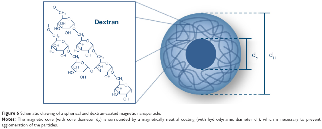 | Figure 6 Schematic drawing of a spherical and dextran-coated magnetic nanoparticle. |
For SPIONs in MPI, Néel relaxation seems to be the dominating mechanism. Of course, the relaxation is also dependent on the SPIONs’ environment, ie, if they are suspended in fluid, as is most often the case in medical applications, or fixed in solid structures, where the Brownian relaxation is consequentially blocked. In principle, a large iron core diameter is desirable for a high magnetic moment and a steep magnetization curve. On the contrary, if the iron core diameter exceeds a critical size, the particles lose their superparamagnetic characteristics. Thus, the most suitable iron core diameter has to be a compromise.
At the beginning of MPI, drive field amplitude and frequency were around 10–20 mT and 25 kHz respectively. Here, an ideal iron core diameter of 30 nm was proposed.1 However, as the relaxation characteristics are also dependent on the drive field amplitude and frequency, the SPIONs’ ideal iron core diameters may vary for different drive field settings. It is believed by some, that for a maximum performance, an MPI tracer should contain homogeneously distributed SPIONs with the respective ideal iron core diameter. Another important factor for the performance of SPIONs in MPI seems to be the particles’ anisotropy. Here, first simulations indicate that a high anisotropy may diminish the performance, whereas smaller anisotropy may enhance it.37 The change of the particles’ magnetization characteristics at different states, ie, after internalization in cells and degradation or integration in solid structures, also has to be kept in mind.38,39
As in other imaging modalities, a SPIONs’ hydrodynamic diameter (see Figure 6) also influences the pharmacokinetics and thus the application.40,41 In the bloodstream, nanoparticles are rapidly marked by endothelial cells in the reticuloendothelial system (RES).42 This effect is mostly dependent on the hydrodynamic diameter and the surface of the SPIONs. SPIONs with a hydrodynamic diameter smaller than 50 nm, known as ultrasmall SPIONs (uSPIONs), circulate longer and can extravasate. Larger particles are usually collected by the RES of liver and spleen. The iron oxide is eliminated slowly just like endogenous iron. Only 16%–21% of the injected dose of iron is excreted in the feces after 84 days.43 Most of the iron is stored in the iron storage protein ferritin. Ferritin can be found in especially high concentrations in tissues that contain cells of the RES, eg, liver, spleen, bone marrow, and lymph nodes.
In the beginning of MPI, existing SPION contrast agents for MRI were evaluated regarding their MPI performance using MPS. Only Resovist (Bayer Pharma AG) showed an acceptable MPI performance (see Figure 7). All other tracers showed a very weak MPI signal, mostly due to too small iron core diameters.44 The good performance of Resovist was surprising, as Gleich and Weizenecker could show that, according to Langevin theory, only particles with a diameter of about 30 nm contribute significantly to the MPI signal, and in Resovist, these particles amount only to 3% of the iron mass of the Resovist solution.1 Subsequent studies showed that in Resovist, the smaller SPIONs form aggregates behaving like monodomain particles, ie, superparamagnetic, with an iron core diameter of 24 nm.45 These aggregates account for 30% of the nanoparticles in Resovist and might explain its good MPI performance.45 Since Resovist is the only commercially available SPION formulation with an acceptable MPI performance, it became the standard of reference in the MPI community. The iron concentration of undiluted Resovist is 0.5 mmol/mL. MPI scans undertaken with clinically approved concentrations of Resovist for MRI examinations in humans, have provided great results in in vivo MPI, eg, the visualization of blood flow in a beating mouse heart.7 Unfortunately Bayer Pharma AG abandoned Resovist in 2009, and it is currently only available in Japan, distributed by I’rom Pharmaceutical (Tokyo, Japan). However, as Resovist is not an ideal MPI tracer with respect to its iron core size and especially its particle size distribution, many research groups started to develop dedicated MPI tracers beforehand.46
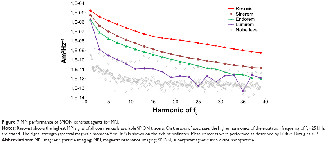 | Figure 7 MPI performance of SPION contrast agents for MRI. |
A variety of strategies has been proposed for the creation of appropriate nanoparticular systems, the most important for MPI are precipitation and thermal decomposition.46,47 To prevent the particles of agglomeration during storage or application, the iron oxide particle cores have to be coated with a biocompatible hull. Dextran, carboxydextran, or other polymeric carbohydrates are frequently used as coating materials. For medical applications, magnetic iron oxide particles in the liquid form must be stabilized. The stabilizer ensures the stability of a colloidal suspension of particles during application. The stabilizer counteracts against the van der Waals interactions as well as magnetic attraction between the particles.
One common approach for MPI is the synthesis of homogeneously distributed single-core SPIONs with a dedicated iron core diameter for ideal MPI characteristics. Khandhar et al have already presented first results of a SPION tracer with an MPS performance twice as good as Resovist. Furthermore, this group predicts an improvement of the spatial resolution of 20% based on the MPS measurements. Starmans et al49 published results of iron oxide nanoparticles micelles (ION-Micelles) outperforming Resovist by a factor of at least 4–6 in MPS. Some groups aim at creating multicore nanoparticles with a big fraction of large aggregates and thus a good MPI performance. Other groups separate multicore aggregates from the smaller particles to achieve a larger fraction of efficient particles.50–54 A list of recently published results in tracer design for MPI is provided in Table 1. Besides these conventional approaches, the use of bacterial magnetosomes as biogenic MPI tracers has been recently proposed. First experimental results show a superior performance compared with Resovist in MPS.55
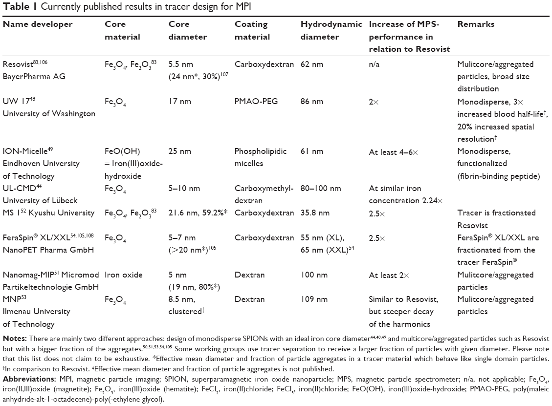 | Table 1 Currently published results in tracer design for MPI |
The use of Resovist as a standard of reference in tracer and hardware development for MPI is very important as it allows for a comparison and interpretation of the results of different research centers, as many working groups use different MPS systems and MPI scanners for evaluation. However, it has to be kept in mind that different batches of Resovist may show a deviating MPS performance up to a factor of three,56 which is a potential source of error.
Scanner geometries and performances
To date, there are mainly three geometries for MPI systems (see Figure 8A–C): closed-bore scanners, where the subject is inserted in the center of a tube-like device; open-bore systems, where the subject lies between two magnets and is accessible from the side; and single-sided coil arrangements intended for integration in beds, tables, or developed as handheld devices.57 With the exception of one commercially available imager,58 most of the MPI systems currently running are working prototypes, acquiring 1D, 2D, or 3D images. An overview of MPI systems and their actual performance is given in Table 2.
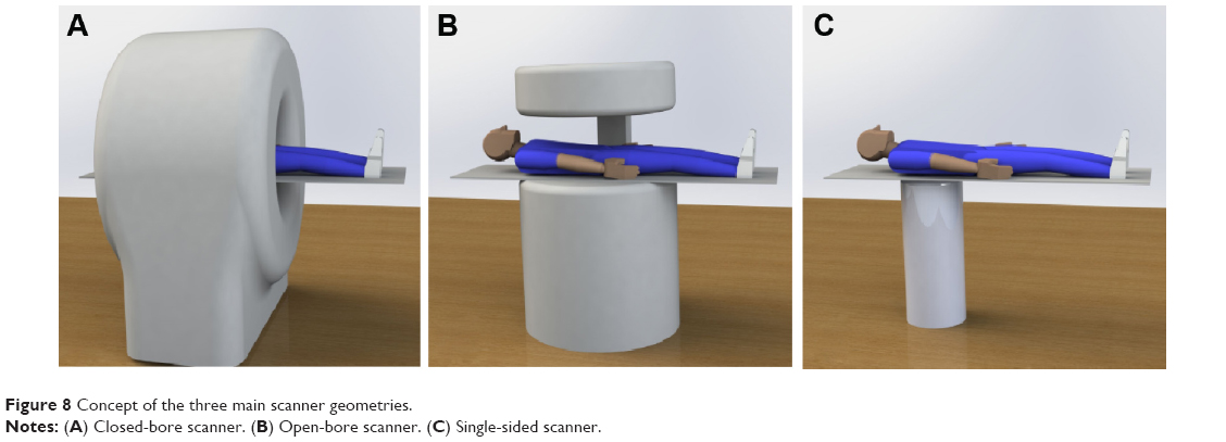 | Figure 8 Concept of the three main scanner geometries. |
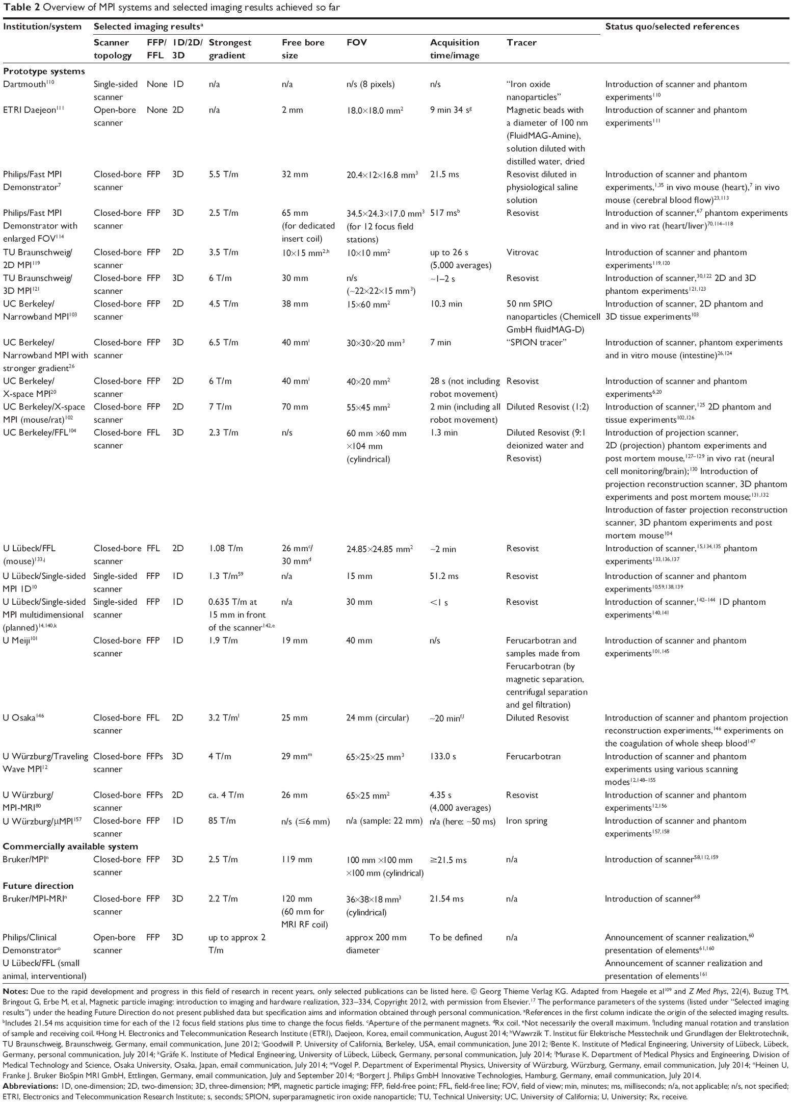 | Table 2 Overview of MPI systems and selected imaging results achieved so far |
The presented performance data include the available free bore, the FOV, the acquisition time per image, the maximal gradient amplitude, as well as the used tracer and the tracer concentration. Spatial resolution and sensitivity have deliberately been left out due to the heterogeneity of criteria used for their determination. Moreover, many research groups have just roughly estimated the spatial resolution or have not explicitly published these data at all. So far, the experimentally proven spatial resolution of MPI lies in the range of one to several millimeters.
The sensitivity of an MPI system depends on many variables, eg, voxel size, scanning time, and coil design and is thus hardly comparable between different scanner geometries in MPI and especially between different modalities like MRI and MPI. However, Gleich theoretically determined the detection limit of MPI for an MPI system with a coil of square shape and a side length of 10 cm with a sample placed 10 cm from the center of the coil.9 Referring to this model, he calculated that it is possible to detect 25 pg of iron oxide [324 nmol(Fe)/L] in 1 second scanning time in a human with MPI. Refering to this, Knopp and Buzug described that for Resovist, if applied according to prescription in a human with a blood volume of 6 liters, the concentration of Resovist would be 116 mol(Fe)/L and thus about 360 times higher than the detection limit of MPI with a voxel size of 1 mm3 and a scanning time of 1 second.2 Ultimately, Gleich depicted the detection limit of MPI as 13 nmol(Fe)/L for a voxel size of 1 mm3 and 13 pmol(Fe)/L for a voxel size of 1 cm3.9 In comparison, Gleich described the sensitivity of MRI to be roughly 50 μmol(Fe)/L, independent of the voxel size.9
Finally, the exact relation between the scanner parameters, the particle characteristics, and the sensitivity as well as the spatial and temporal resolution of the acquired images is still under investigation.59 What can be already stated with a fair amount of certainty is that the spatial resolution strongly depends on the gradient of the magnetic field strength and the SPIONs’ properties.21 With higher gradient field strength, the FFP and FFL narrow allowing to assign the SPION’s signal to a smaller region in space and ultimately to enhance the spatial resolution.
Scaling up MPI
To date, most bore diameters are designed to accommodate mouse- and rat-sized animals. As MPI is intended to be used in a clinical environment, its development is closely connected to human physiology and medical ambitions. To mention just one of the requirements for its clinical use, the scanned volume has to have a clinically relevant size, eg, the volume of the human heart. A whole-body MPI system for high speed imaging is currently being developed by Philips,60 aiming at a gradient amplitude of 2 T/m and a field of view with a diameter of 200 mm.61
Safety considerations
Enlarging the scanning volume is mainly limited by the physiological effects of time-varying magnetic fields. The achievable size of the covered imaging area is kept relatively small due to two phenomena well known to scientists who work in the field of MRI. These phenomena are the peripheral nerve stimulation (PNS) and tissue heating with the specific absorption rate as a measure for the rate at which energy is absorbed by the human body when exposed to an electromagnetic field. The occurrence of both would impair patients’ welfare.62–64 But the experience gained over the last decades with MRI security and also instrument heating could and should be of good use for the safety of MPI during its transition from preclinical into clinical use.65
The frequencies applied in most present MPI systems are in the range of 10 kHz to 100 kHz, and their peak amplitudes are around 10 mT to 100 mT. As the human body is conductive, the applied time-varying magnetic fields induce eddy currents, which may lead to the aforementioned PNS.64,66 A conclusion that can be drawn from current studies on PNS is that the amplitude of the drive field in a clinical MPI system will have to be clearly below 10 mT.63 This is much lower than on preclinical systems that use amplitudes up to twice as high.67,68 Tissue heating seems to become an issue above the frequency range of about 25 kHz.66,69
The reduction of the drive field amplitude leads to a reduction of the volume that can be quickly encoded.60 Nonetheless, an additional extension of the imaging area within the aforementioned limits seems achievable through the introduction of additional fields. These specific fields, introduced as focus fields, enlarge the relatively small “core scanning volume” to achieve a bigger in size “clinical volume”, ie, total FOV.70 As one result of these considerations, the drive frequencies for a clinical system have been shifted from the traditional 25 kHz range to 150 kHz, increasing the available drive field amplitude.71 While first studies have been conducted,65,66,69 further ones are needed to fully understand the complex interaction of multiple magnetic fields and their effect on the human body.
Safety considerations concerning the biocompatibility of SPIONs are of equal importance. Nanoparticle-derived adverse health effects have always been an issue in the field of nanoparticle science. In order to use MPI in a clinical environment on humans, the safety of the utilized tracers has to be ensured. Therfore, extensive studies on the pharmacokinetics and the influence of potential MPI tracers on human cells and organs have to be conducted.
Proposed mechanisms for the induction of the cytotoxicity of uncoated iron oxide nanoparticles are the release of (toxic) irons, surface catalyzed reactions that lead to cytotoxic products or stress and stimuli caused by the particles’ presence.72 Recent in vitro studies investigating the uptake and cytotoxicity of dextran-coated MPI tracers on human adult stem cells indicate a high stability and biocompatibility of dextran-coated SPIONs.73
Medical applications
As already mentioned in the “Introduction”, MPI has the advantage of three-dimensional imaging with a very high temporal resolution, a high sensitivity and spatial resolution, and the absence of hazardous ionizing radiation. Furthermore, MPI operates without contrast agents containing nephrotoxic (iodine based) or serious systemic side effects, ie, nephrogenic systemic fibrosis (gadolinium based) in patients with renal insufficiency.74 The used SPIONs are eliminated via the iron metabolism. Thus, only a significant overdose of SPIONs will lead to toxic effects in terms of iron overload. In fact, SPIONs are even utilized for treatment of iron deficiency anemia in adult patients with chronic kidney disease.75 It could already be demonstrated that MPI is possible with clinically approved doses of SPIONs.7 Also, SPIONs can be tailored to achieve a longer blood circulation, even loading of erythrocytes for very long circulating SPIONs (so called blood pool tracers) is possible.25,76 This may allow repeated examinations without the need of tracer reapplication.
MPI is a truly quantitative method, as the strength of the MPI signal is proportional to the SPIONs’ concentration, allowing quantification of tissue perfusion and stenosis.77 Especially for vascular and perfusion imaging, the missing background signal of the body is an advantage. The FOV of MPI can be tailored to the specific need, ie, from a larger FOV for a general survey to a smaller FOV with a substantially higher spatial resolution for evaluation of pathologies in detail.
Considering these facts, MPI seems suitable for a wide range of applications, ie, vascular, gastrointestinal, pulmonary imaging, and the wide range of cellular and targeted imaging or imaging of the RES.9 Currently, it seems that cardiovascular imaging, cellular and targeted imaging, and imaging of the RES are the focus of research regarding potential applications.4,5
Vascular imaging
Current methods in vascular imaging are conventional x-ray angiography and digital subtraction angiography (DSA) and computed tomography and magnet resonance angiography (CTA and MRA). For diagnostic purposes, MRA and especially CTA are the gold standard; for interventional purposes, DSA is considered the method of choice. Unfavorably, conventional DSA and CTA burden patients and physicians with a considerable amount of ionizing radiation. Furthermore, DSA provides only two-dimensional images and does not allow exact quantification of pathologies like stenosis. CTA and MRA overestimate vascular stenosis78,79 and are limited in time resolved imaging, MRA due to limitations in temporal resolution and CTA due to restrictions owing to radiation protection. MPI can overcome most of these limitations. Visualization of the vasculature and quantitative evaluation of pathologies like stenosis are surely the first step.77 But MPI could, furthermore, provide information about tissue perfusion and functional parameters to assess myocardial viability and function, for example. The advantage of MPI compared with MRI is that the whole organ could be assessed three-dimensionally with such a high temporal resolution that breath hold sequences would not be necessary anymore or at least be substantially shorter. Furthermore, all the information could be collected in one go as a “one stop shop.” First in vivo experiments could demonstrate the high temporal resolution by visualizing the beating of a mouse heart in real-time using Resovist.7 Of course, in MPI morphological information can only be obtained of contrasted structures.68 Here, MRI provides more information; that is why MPI/MRI hybrid systems are already being investigated to combine the advantages of both systems.68,80
With an open or single-sided scanner geometry (see section “Scanner geometries and performances”), MPI allows supreme patient access. In combination with the very good SNR, temporal and spatial resolution, a tracer with a good safety profile, and the absence of ionizing radiation, MPI is an interesting option for vascular interventions as well. But as MPI is only visualizing the SPIONs, devices for vascular interventions need to be labeled for use in MPI. This can be achieved by loading the lumen with SPIONs, applying a SPION-based coating to the devices or even integrating SPIONs into the structure of the catheters.24 Furthermore, the labeling of the devices has to be discernible from the intravascular contrast, which can be achieved by using different concentrations or even different SPIONs. Finally, the safety of the interventional devices has to be considered.81,82 Besides the necessity of biocompatibility, potential heating of instruments in the oscillating magnetic field has to be kept in mind as in MRI. In MPI, steel-based instruments seem to be prone to substantial heating effects (see Figure 9), at least in vitro.82
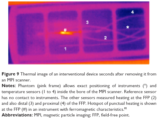 | Figure 9 Thermal image of an interventional device seconds after removing it from an MPI scanner. |
These application scenarios are most often described for use in diagnostic, interventional cardiovascular, and peripheral vascular radiology. However, cerebrovascular applications seem to be interesting as well. Perfusion imaging in diagnosis of ischemia, in particular, is still suboptimal and requires CT-perfusion scans with high doses of ionizing radiation. Furthermore, patients with intracranial hemorrhage, especially subarachnoid hemorrhage after rupture of an intracranial aneurysm, often develop spasms of the intracranial arteries, which can lead to serious brain infarction. The diagnosis of intracranial arterial spasms using Doppler ultrasound is difficult. DSA is still gold standard but always requires an interventional procedure and, as well as the alternative perfusion CT, is socialized with high and repeated doses of ionizing radiation. Here, perfusion MPI could be a valuable addition. In a scenario with a single-sided scanner geometry that is integrated in the headboard of the bed and blood pool tracers, it might even be possible to monitor the brain perfusion permanently. Of course, this could work also for monitoring the reperfusion of brain tissue during thrombolysis therapy of acute brain infarction.
Cellular and targeted imaging
Although the use of SPIONs in clinical MRI has declined in the last few years, there are many promising SPION-based approaches to clinical imaging, especially regarding the wide range of targeted imaging. SPIONs are generally collected by the body’s RES. Larger SPIONs like Resovist are cleared very fast from the bloodstream by the RES in liver and spleen, which can be used for the detection of hepatocellular carcinoma, for example.83 Smaller SPIONs circulate longer, extravasate, and are then collected by the cells of the RES to accumulate in lymph nodes. This principle was used in lymph node staging of pelvic cancer.84,85 Furthermore, the affinity of SPIONs toward cells of the RES has been used for inflammation imaging, eg, in arthritis or even vulnerable atherosclerotic plaques.86–88 SPIONs were used also for tumor imaging, utilizing the enhanced permeability and retention effect of the tumor vessels or the defective blood–brain barrier in terms of passive targeting.89 All these applications have in common that they rely on general characteristics of the SPIONs and “the underlying specific pathology”. In the setting of MPI, the use of SPIONs in combination with a handheld MPI probe, similar to ultrasound, for the detection of the sentinel lymph node in breast cancer diagnostics has been already proposed as a clinical application.90
For more specific applications, SPIONs can be modified by different coatings and especially by adding ligands, such as antibodies, peptides, polysaccharides, and other molecules for active targeting, that is, the SPIONs only bind to specific cells. Another possible approach is to label specific cells with SPIONs ex vivo and monitor their behavior in vivo, eg, their migration, by visualizing the intracellular SPIONs (cellular imaging). Both approaches are already being extensively researched for many disease entities. The possibilities seem endless, the detection of tumors as the most prevalent application, but others such as detection and monitoring of inflammation, cardiovascular disease, apoptosis, transplant rejection reactions, or neurodegenerative disorders are also being investigated. Recently Ittrich et al summarized these applications.91 Most of these approaches are, in principle, designed for SPION-based in vivo MR imaging. However, no targeted or cellular imaging approach has reached clinical routine yet. The main reason is most certainly the limited sensitivity of MRI.92
Sensitivity for SPION detection in MPI exceeds that in MRI, as MPI visualizes SPIONs directly by detecting the particle signal, which is 22×106 times stronger than the proton’s magnetization in MRI.93 Saritas et al describe a detection limit for their current MPI scanner system of about 500 stem cells when labelled with Resovist; due to further development in scanner and SPION technology they see “potential for orders-of-magnitude improvement.”93 Bulte et al specify the detection limit of Resovist labeled mesenchymal stem cells below 100 cells.94 Again, due to further development especially in the field of MPI-dedicated SPIONs, this number will improve. These data show the potential of MPI for cellular and targeted imaging in vivo due to its sensitivity. When very high temporal resolution is not necessary, as most often is the case in targeted/cellular imaging, it can be traded in for further enhancing MPI sensitivity. Nevertheless, MPI is not as sensitive as nuclear imaging. However, the main advantages of MPI are that there is no ionizing radiation involved and that the shelf life of SPIONs is by orders of magnitudes longer than that of radionuclides, which will improve handling, work flow, and lower costs. Moreover, production costs of SPIONs are less than those of radionuclides in the first place.
In terms of cellular imaging, the internalization of Resovist in red blood cells for a substantially prolonged blood circulation time and MPI contrast could already be demonstrated as an example for in vivo cellular imaging in MPI.25 The use of SPIONs to label head and neck squamous cell carcinoma cells for visualization of their migration has recently been proposed.95 First experiments toward using MPI as a tool for theranostics have been published;96,97 functionalized MPI tracers have already been described as well.49,98
Until now, most of these scenarios still need to be assessed in vivo. A big step toward standardized in vivo MPI research has been made by the development of the first commercially available MPI scanner for small animals. Currently, two of those systems are being installed at German Universities in Hamburg and Berlin.99 Many working groups are engaged in development of dedicated SPIONs for MPI with promising results, another very important step to improve MPI performance on the one hand and enable standardized and reproducible research on the other hand.
Conclusion and outlook
MPI is a potent new imaging modality with a unique combination of capabilities that has the potential to enrich today’s arsenal of imaging options in modern medicine. The development is pointed toward the ultimate goal of a clinical human-sized scanner system.
The next step on this path is the implementation of a first clinical demonstrator. Once the technical challenges of upscaling will have been overcome, the first clinical demonstrator will help to actually evaluate the performance of MPI at a whole-body scale. Then, different acquisition schemes will have to be studied on a clinically relevant scenario, taking into account the different trade-offs to be made, particularly regarding PNS and energy absorption (specific absorption rate [SAR]).63,71,100
As realized right from the beginning of the story of MPI, it is the SPION that will be the crucial part for the ultimate success of MPI as a method. With new biocompatible particles that are optimized for use in MPI, the system’s performance will increase dramatically, especially in terms of spatial resolution and sensitivity. With that in mind and besides clinical applications like vascular imaging and interventions, MPI has the potential to pick up SPION-based concepts for cellular, targeted imaging, and theranostics and to enable their translation into clinical imaging.
With dedicated MPI tracers on the way, without any unsolvable technical challenges ahead, and with a growing knowledge about safety issues, there is no reason why the transition from current experimental systems to clinically suitable scanners and ultimately to human MPI should not succeed.
Acknowledgments
The authors would like to thank Dr rer. nat. Jürgen Rahmer and Philips for the data acquisition and reconstruction of Figures 3, 7, 9, and 10.
The research leading to these results has received funding from the Federal Ministry of Education and Research, Germany (BMBF), 13N11090, the European Union and the State Schleswig-Holstein (Programme for the Future – Economy: 122-10-004), and the European Union Seventh Framework Programme (FP7/2007–2013) under grant agreement n° 604448.
Disclosure
The authors report no conflicts of interest in this work.
References
Gleich B, Weizenecker J. Tomographic imaging using the nonlinear response of magnetic particles. Nature. 2005;435(7046):1214–1217. | ||
Knopp T, Buzug TM. Magnetic Particle Imaging: An Introduction to Imaging Principles and Scanner Instrumentation. Heidelberg, Germany: Springer; 2012. | ||
Goodwill PW, Tamrazian A, Croft LR, et al. Ferrohydrodynamic relaxometry for magnetic particle imaging. Appl Phys Lett. 2011;98:262502. | ||
Borgert J, Schmidt JD, Schmale I, et al. Fundamentals and applications of magnetic particle imaging. J Cardiovasc Comput Tomogr. 2012;6(3):149–153. | ||
Goodwill PW, Saritas EU, Croft LR, et al. X-Space MPI: Magnetic Nanoparticles for Safe Medical Imaging. Adv Mater. 2012;24(28): 3870–3877. | ||
Goodwill PW, Lu K, Zheng B, Conolly SM. An x-space magnetic particle imaging scanner. Rev Sci Instrum. 2012;83(3):033708. | ||
Weizenecker J, Gleich B, Rahmer J, Dahnke H, Borgert J. Three-dimensional real-time in vivo magnetic particle imaging. Phys Med Biol. 2009;54(5):L1–L10. | ||
Knopp T, Sattel TF, Biederer S, et al. Model-based reconstruction for magnetic particle imaging. IEEE Trans Med Imaging. 2010;29(1):12–18. | ||
Gleich B. Principles and Applications of Magnetic Particle Imaging. Wiesbaden, Germany: Springer Vieweg; 2013. | ||
Sattel TF, Knopp T, Biederer S, et al. Single-sided device for magnetic particle imaging. J Phys Appl Phys. 2009;42(2):022001. | ||
Kaethner C, Ahlborg M, Knopp T, Sattel TF, Buzug TM. Efficient gradient field generation providing a multi-dimensional arbitrary shifted field-free point for magnetic particle imaging. J Appl Phys. 2014;115(4):0449101–0449105. | ||
Vogel P, Rückert MA, Klauer P, Kullmann WH, Jakob PM, Behr VC. Traveling wave magnetic particle imaging. IEEE Trans Med Imaging. 2014;33(2):400–407. | ||
Weizenecker J, Gleich B, Borgert J. Magnetic particle imaging using a field free line. J Phys Appl Phys. 2008;41(10):105009. | ||
Knopp T, Sattel TF, Biederer S, Buzug TM. Field-free line formation in a magnetic field. J Phys Math Theor. 2010;43(1):012002. | ||
Erbe M, Weber M, Sattel TF, Buzug TM. Experimental validation of an assembly of optimized curved rectangular coils for the use in dynamic field free line magnetic particle imaging. Curr Med Imaging Rev. 2013; 9(2):89–95. | ||
Knopp T, Biederer S, Sattel T, et al. Trajectory analysis for magnetic particle imaging. Phys Med Biol. 2009;54(2):385–397. | ||
Buzug TM, Bringout G, Erbe M, et al. Magnetic particle imaging: introduction to imaging and hardware realization. Z Med Phys. 2012; 22(4):323–334. | ||
Grüttner M, Knopp T, Franke J, et al. On the formulation of the image reconstruction problem in magnetic particle imaging. Biomed Tech (Berl). 2013;58(6):583–591. | ||
Knopp T, Rahmer J, Sattel TF, et al. Weighted iterative reconstruction for magnetic particle imaging. Phys Med Biol. 2010;55(6):1577–1589. | ||
Goodwill PW, Conolly SM. Multidimensional x-space magnetic particle imaging. IEEE Trans Med Imaging. 2011;30(9):1581–1590. | ||
Rahmer J, Weizenecker J, Gleich B, Borgert J. Signal encoding in magnetic particle imaging: properties of the system function. BMC Med Imaging. 2009;9:4. | ||
Rahmer J, Weizenecker J, Gleich B, Borgert J. Analysis of a 3-D system function measured for magnetic particle imaging. IEEE Trans Med Imaging. 2012;31(6):1289–1299. | ||
Rahmer J, Gleich B, Weizenecker J, Borgert J. 3D real-time magnetic particle imaging of cerebral blood flow in living mice. In: Proceedings of the International Society for Magnetic Resonance in Medicine (ISMRM); May 1–7, 2010; Stockholm, Sweden: Page 714. | ||
Haegele J, Rahmer J, Gleich B, et al. Magnetic particle imaging: visualization of instruments for cardiovascular intervention. Radiology. 2012;265(3):933–938. | ||
Rahmer J, Antonelli A, Sfara C, et al. Nanoparticle encapsulation in red blood cells enables blood-pool magnetic particle imaging hours after injection. Phys Med Biol. 2013;58(12):3965–3977. | ||
Goodwill P, Scott G, Stang P, Lee GC, Morris D, Conolly S. Direct imaging of spios in mice using magnetic particle imaging: instrument construction and 3D imaging. In: Proceedings of the International Society for Magnetic Resonance in Medicine (ISMRM); April 18–24, 2009; Honolulu, Hawaii, USA. Page 596. | ||
Biederer S, Knopp T, Sattel TF, et al. Magnetization response spectroscopy of superparamagnetic nanoparticles for magnetic particle imaging. J Phys D: Appl Phys. 2009;42:205007. | ||
Wawrzik T, Schilling M, Ludwig F. Debye-based frequency-domain magnetization model for magnetic nanoparticles and its application to viscosity dependent MPS measurements. Presented at: The 4th International Workshop on Magnetic Particle Imaging (IWMPI); March 27–29, 2014; Berlin, Germany. | ||
Rauwerdink AM, Hansen EW, Weaver JB. Nanoparticle temperature estimation in combined ac and dc magnetic fields. Phys Med Biol. 2009; 54(19):L51–L55. | ||
Wawrzik T, Ludwig F, Schilling M. Magnetic particle imaging: exploring particle mobility. Springer Proc Phys. 2012;140:21–25. | ||
Graeser M, Knopp T, Grüttner M, Sattel TF, Buzug TM. Analog receive signal processing for magnetic particle imaging. Med Phys. 2013;40(4):042303. | ||
Reeves DB, Weaver JB. Magnetic nanoparticle sensing: decoupling the magnetization from the excitation field. J Phys Appl Phys. 2014; 47:045002. | ||
Ruhland B, Baumann K, Knopp T, et al. Magnetic Particle Imaging durch Superparamagnetische Nanopartikel zur Sentinellymphknotendetektion beim Mammakarzinom. Geburtshilfe Frauenheilkd. 2009;69(09):A096. German. | ||
Dhavalikar R, Rinaldi C. On the effect of finite magnetic relaxation on the magnetic particle imaging performance of magnetic nanoparticles. J Appl Phys. 2014;115(7):074308. | ||
Gleich B, Weizenecker J, Borgert J. Experimental results on fast 2D-encoded magnetic particle imaging. Phys Med Biol. 2008;53(6): N81–N84. | ||
Deissler RJ, Wu Y, Martens MA. Dependence of Brownian and Néel relaxation times on magnetic field strength. Med Phys. 2014; 41(1):012301. | ||
Weizenecker J, Gleich B, Rahmer J, Borgert J. Micro-magnetic simulation study on the magnetic particle imaging performance of anisotropic mono-domain particles. Phys Med Biol. 2012;57(22):7317–7327. | ||
Rahmer J, Rahn H, Henrich F, Odenbach S, Gleich B, Borgert J. Imaging of iron oxide nanoparticles embedded in polyurethane. Presented at: the 3rd International Workshop on Magnetic Particle Imaging (IWMPI); March 23–24, 2013; Berkeley, California, USA. | ||
Arami H, Krishnan KM. Intracellular performance of tailored nanoparticle tracers in magnetic particle imaging. J Appl Phys. 2014; 115(17):17B306. | ||
Pankhurst QA, Connolly J, Jones SK, Dobson J. Applications of magnetic nanoparticles in biomedicine. J Phys Appl Phys. 2003;36(13):R167. | ||
Pankhurst QA, Thanh NTK, Jones SK, Dobson J. Progress in applications of magnetic nanoparticles in biomedicine. J Phys Appl Phys. 2009; 42(22):224001. | ||
Almeida JP, Chen AL, Foster A, Drezek R. In vivo biodistribution of nanoparticles. Nanomedicine (Lond). 2011;6(5):815–835. | ||
Gourtsoyiannis NC. Clinical MRI of the Abdomen. Berlin: Springer-Verlag; 2011. | ||
Lüdtke-Buzug K, Haegele J, Biederer S, et al. Comparison of commercial iron oxide-based MRI contrast agents with synthesized high-performance MPI tracers. Biomed Tech (Berl). 2013;58(6):527–533. | ||
Eberbeck D, Wiekhorst F, Wagner S, Trahms L. How the size distribution of magnetic nanoparticles determines their magnetic particle imaging performance. Appl Phys Lett. 2011;98(18):182502. | ||
Kratz H, Eberbeck D, Wagner S, Taupitz M, Schnorr J. Synthetic routes to magnetic nanoparticles for MPI. Biomed Tech (Berl). 2013; 58(6):509–515. | ||
Lüdtke-Buzug K. From synthesis to clinical Application. Magnetic nanoparticles. Chem Unserer Zeit. 2012;46(1):32–39. | ||
Khandhar AP, Ferguson RM, Arami H, Krishnan KM. Monodisperse magnetite nanoparticle tracers for in vivo magnetic particle imaging. Biomaterials. 2013;34(15):3837–3845. | ||
Starmans LW, Burdinski D, Haex NP, et al. Iron oxide nanoparticle-micelles (ION-micelles) for sensitive (molecular) magnetic particle imaging and magnetic resonance imaging. PLoS One. 2013;8(2):e57335. | ||
Ludwig F, Eberbeck D, Löwa N, et al. Characterization of magnetic nanoparticle systems with respect to their magnetic particle imaging performance. Biomed Tech (Berl). 2013;58(6):535–545. | ||
Eberbeck D, Dennis CL, Huls NF, Krycka KL, Grüttner C, Westphal F. Multicore magnetic nanoparticles for magnetic particle imaging. IEEE Trans Magn. 2013;49(1):269–274. | ||
Yoshida T, Othman NB, Enpuku K. Characterization of magnetically fractionated magnetic nanoparticles for magnetic particle imaging. J Appl Phys. 2013;114(17):173908. | ||
Dutz S, Buske N, Löwa N, Eberbeck D, Trahms L. Tracers for magnetic particle imaging consisting of agglomerated single cores. Presented at: the 4th International Workshop on Magnetic Particle Imaging (IWMPI); March 27–29, 2014; Berlin, Germany. Page 138. | ||
Gehrke N, Briel A, Ludwig F, Remmer H, Wawrzik T, Wellert S. New perspectives for MPI: a toolbox for tracer research. In: Buzug TM, Borgert J, editors. Magnetic Particle Imaging. Vol 140: Berlin: Springer-Verlag; 2012:99–103. | ||
Kraupner A, Heinke D, Uebe R, et al. Bacterial magnetosomes as a new type of biogenic MPI tracers. Presented at: the 4th International Workshop on Magnetic Particle Imaging (IWMPI); March 27–29, 2014; Berlin, Germany. Pages 141–142. | ||
Ide A, Roohi F, Pietsch H, Schuetz G. Synthetic approach for iron oxide nanoparticles suitable as tracer for magnetic particle imaging. Presented at: the 4th International Workshop on Magnetic Particle Imaging (IWMPI); March 27–29, 2014; Berlin, Germany. Page 40. | ||
Kaethner C, Ahlborg M, Gräfe K, Bringout G, Sattel T, Buzug TM. Asymmetric scanner design for interventional scenarios in magnetic particle imaging. IEEE Trans Magn. In press, 2014. | ||
Bruker. Bruker Announces the World’s First Preclinical Magnetic Particle Imaging (MPI) System. 2013 Sept 19. Billerica, MA: Bruker; 2013. Available from: http://www.bruker.com/news-records/single-view/article/bruker-announces-the-worlds-first-preclinical-magnetic-particle-imaging-mpi-system.html. Accessed July 6, 2014. | ||
Knopp T, Biederer S, Sattel TF, Erbe M, Buzug TM. Prediction of the spatial resolution of magnetic particle imaging using the modulation transfer function of the imaging process. IEEE Trans Med Imaging. 2011;30(6):1284–1292. | ||
Borgert J, Schmidt JD, Schmale I, et al. Perspectives on clinical magnetic particle imaging. Biomed Tech (Berl). 2013;58(6):551–556. | ||
Bontus C, Gleich B, David B, Mende O, Borgert J. Concept of a generator for the selection- and focus field of a clinical MPI scanner. Presented at: the 4th International Workshop on Magnetic Particle Imaging (IWMPI); March 27–29, 2014; Berlin, Germany. Page 67. | ||
Reilly JP. Magnetic field excitation of peripheral nerves and the heart: a comparison of thresholds. Med Biol Eng Comput. 1991;29(6):571–579. | ||
Saritas EU, Goodwill PW, Zhang GZ, Conolly SM. Magnetostimulation limits in magnetic particle imaging. IEEE Trans Med Imaging. 2013; 32(9):1600–1610. | ||
Doessel O, Bohnert J. Safety considerations for magnetic fields of 10 mT to 100 mT amplitude in the frequency range of 10 kHz to 100 kHz for magnetic particle imaging. Biomed Tech (Berl). 2013;58(6):611–621. | ||
Schmale I, Gleich B, Rahmer J, Bontus C, Schmidt J, Borgert J. MPI Safety in the View of MRI Safety Norms. Presented at: the 4th International Workshop on Magnetic Particle Imaging (IWMPI); March 27–29, 2014; Berlin, Germany. Page 15. | ||
Doessel O, Bohnert J. Considerations on safety limits for magnetic fields used in magnetic particle imaging. Presented at: the 4th International Workshop on Magnetic Particle Imaging (IWMPI); March 27–29, 2014; Berlin, Germany. Page 14. | ||
Gleich B, Weizenecker J, Timminger H, et al. Fast MPI demonstrator with enlarged field of view. In: Proceedings of the International Society for Magnetic Resonance in Medicine (ISMRM); May 1–7, 2010; Stockholm, Sweden. Page 218. | ||
Franke J, Heinen U, Matthies L, et al. First hybrid MPI-MRI imaging system as integrated design for mice and rats: description of the instrumentation setup. Presented at: the 3rd International Workshop on Magnetic Particle Imaging (IWMPI); March 23–24, 2013; Berkeley, California, USA. | ||
Saritas EU, Goodwill PW, Zhang GZ, Yu W, Conolly SM. Safety limits for human-size magnetic particle imaging systems. Springer Proc Phys. 2012;140:325–330. | ||
Schmale I, Rahmer J, Gleich B, et al. First phantom and in vivo MPI images with an extended field of view. In: Proceedings of the SPIE Symposium on Medical Imaging: Biomedical Applications in Molecular, Structural, and Functional Imaging. Weaver JB, Molthen RC, editors. 2011;7965:796510. | ||
Rahmer J, Borgert J, Gleich B, et al. Strategies for fast MPI within the limits determined by nerve stimulation. Presented at: the 4th International Workshop on Magnetic Particle Imaging (IWMPI); March 27–29, 2014; Berlin, Germany. Page 16. | ||
Brunner TJ, Wick P, Manser P, et al. In vitro cytotoxicity of oxide nanoparticles: comparison to asbestos, silica, and the effect of particle solubility. Environ Sci Technol. 2006;40(14):4374–4381. | ||
Schneider D, Lüdtke-Buzug K. Biomaterials for regenerative medicine: Cytotoxicity of superparamagnetic iron oxide nanoparticles in stem cells. Springer Proc Phys. 2012(140):117–122. | ||
Wang Y, Alkasab TK, Narin O, et al. Incidence of nephrogenic systemic fibrosis after adoption of restrictive gadolinium-based contrast agent guidelines. Radiology. 2011;260(1):105–111. | ||
Ferumoxytol (Feraheme) – a new parenteral iron formulation. Med Lett Drugs Ther. 2010;52(1334):23. | ||
Haegele J, Duschka RL, Graeser M, et al. Magnetic particle imaging: kinetics of the intravascular signal in vivo. Int J Nanomedicine. 2014; 9:4203–4209. | ||
Haegele J, Rahmer J, Duschka R, et al. Magnetic Particle Imaging (MPI): Visualization and Quantification of Vascular Stenosis Phantoms. Proceedings of the 4th International Workshop on Magnetic Particle Imaging (IWMPI); March 27–29, 2014; Berlin, Germany. Pages 57–58. | ||
Nonent M, Ben Salem D, Serfaty JM, et al. Overestimation of moderate carotid stenosis assessed by both Doppler US and contrast enhanced 3D-MR angiography in the CARMEDAS study. J Neuroradiol. 2011; 38(3):148–155. | ||
Buerke B, Puesken M, Wittkamp G, et al. Bone subtraction CTA for transcranial arteries: intra-individual comparison with standard CTA without bone subtraction and TOF-MRA. Clin Radiol. 2010;65(6): 440–446. | ||
Vogel P, Lother S, Rückert M, et al. MRI meets MPI: A bimodal MPI-MRI tomograph. IEEE Trans Med Imaging. 2014;33(10):1954–1959. | ||
Haegele J, Biederer S, Wojtczyk H, et al. Toward cardiovascular interventions guided by magnetic particle imaging: first instrument characterization. Magn Reson Med. 2013;69(6):1761–1767. | ||
Duschka RL, Wojtczyk H, Panagiotopoulos N, et al. Safety measurements for heating of instruments for cardiovascular interventions in magnetic particle imaging (MPI) – first experiences. J Healthc Eng. 2014;5(1):79–93. | ||
Reimer P, Balzer T. Ferucarbotran (Resovist): a new clinically approved RES-specific contrast agent for contrast-enhanced MRI of the liver: properties, clinical development, and applications. Eur Radiol. 2003; 13(6):1266–1276. | ||
Heesakkers RA, Hovels AM, Jager GJ, et al. MRI with a lymph-node-specific contrast agent as an alternative to CT scan and lymph-node dissection in patients with prostate cancer: a prospective multicohort study. Lancet Oncol. 2008;9(9):850–856. | ||
Heesakkers RA, Jager GJ, Hovels AM, et al. Prostate cancer: detection of lymph node metastases outside the routine surgical area with ferumoxtran-10-enhanced MR imaging. Radiology. 2009;251(2):408–414. | ||
Sigovan M, Boussel L, Sulaiman A, et al. Rapid-clearance iron nanoparticles for inflammation imaging of atherosclerotic plaque: initial experience in animal model. Radiology. 2009;252(2):401–409. | ||
Ruehm SG, Corot C, Vogt P, Kolb S, Debatin JF. Magnetic resonance imaging of atherosclerotic plaque with ultrasmall superparamagnetic particles of iron oxide in hyperlipidemic rabbits. Circulation. 2001;103(3):415–422. | ||
Lefevre S, Ruimy D, Jehl F, et al. Septic arthritis: monitoring with USPIO-enhanced macrophage MR imaging. Radiology. 2011;258(3): 722–728. | ||
Iyer AK, Khaled G, Fang J, Maeda H. Exploiting the enhanced permeability and retention effect for tumor targeting. Drug Discov Today. 2006;11(17–18):812–818. | ||
Finas D, Baumann K, Sydow L, et al. Lymphatic tissue and superparamagnetic nanoparticles – magnetic particle imaging for detection and distribution in a breast cancer model. Biomed Tech (Berl). Epub 2013 Sep 7. | ||
Ittrich H, Peldschus K, Raabe N, Kaul M, Adam G. Superparamagnetic iron oxide nanoparticles in biomedicine: applications and developments in diagnostics and therapy. Rofo. 2013;185(12):1149–1166. | ||
Dassler K, Roohi F, Lohrke J, et al. Current limitations of molecular magnetic resonance imaging for tumors as evaluated with high-relaxivity CD105-specific iron oxide nanoparticles. Invest Radiol. 2012;47(7):383–391. | ||
Saritas EU, Goodwill PW, Croft LR, et al. Magnetic particle imaging (MPI) for NMR and MRI researchers. J Magn Reson. 2013;229:116–126. | ||
Bulte JW, Walczak P, Bernhard S, et al. Developing cellular MPI: initial experience. Presented at: the 1st International Workshop on Magnetic Particle Imaging (IWMPI); March 18–19, 2010; Lübeck, Germany. Pages 201–205. | ||
Pries R, Lindemann A, Luedtke-Buzug K, Wollenberg B. Novel developed superparamagnetic dextran coated iron oxide nanoparticles (SPION) as a potential tool for HNSCC tumor cell detection and its influence on the biological properties. Presented at: the 4th International Workshop on Magnetic Particle Imaging (IWMPI); March 27–29, 2014; Berlin, Germany. Page 159. | ||
Bleul R, Löwa N, Thiermann R, et al. Continously manufactured magnetic polymerosomes as potential theranostic tools in nanomedicine. Presented at: the 4th International Workshop on Magnetic Particle Imaging (IWMPI); March 27–29, 2014; Berlin, Germany. Pages 149–150. | ||
Buske N, Schelero N, Dähne L, Krumbein I, Reichenbach JR, Dutz S. Ferrofluids of modified Ultra Small Magnetic Particles for application in Theranostics. Presented at: the 4th International Workshop on Magnetic Particle Imaging (IWMPI); March 27–29, 2014; Berlin, Germany. Page 140. | ||
Arami H, Krishnan KM. Highly stable amine functionalized iron oxide nanoparticles designed for magnetic particle imaging (MPI). IEEE Trans Med Imaging. 2013;49(7):3500–3503. | ||
Deutsche Forschungsgemeinschaft. Information für die Wissenschaft Nr. 65: Großgeräteinitiative 2012: Magnetic Particle Imaging (MPI). Bonn: Deutsche Forschungsgemeinschaft; 2012. Available from: http://dfg.de/foerderung/info_wissenschaft/archiv/2011/info_wissenschaft_11_65/index.html. Accessed Jun 21, 2014. | ||
Schmale I, Gleich B, Schmidt J, et al. Human PNS and SAR study in the frequency range from 24 to 162 kHz. Presented at: the 3rd International Workshop on Magnetic Particle Imaging (IWMPI); March 23–24, 2013; Berkeley, California, USA. | ||
Ishihara Y, Honma T, Nohara S, Ito Y. Evaluation of magnetic nanoparticle samples made from biocompatible ferucarbotran by time-correlation magnetic particle imaging reconstruction method. BMC Med Imaging. 2013;13:15. | ||
Goodwill PW, Croft LR, Konkle JJ, et al. A 7 T/M 3D X-space MPI mouse and rat scanner. Presented at: the 3rd International Workshop on Magnetic Particle Imaging (IWMPI); March 23–24, 2013; Berkeley, California, USA. | ||
Goodwill PW, Scott GC, Stang PP, Conolly SM. Narrowband magnetic particle imaging. IEEE Trans Med Imaging. 2009;28(8):1231–1237. | ||
Konkle JJ, Goodwill PW, Saritas EU, Zheng B, Lu K, Conolly SM. Twenty-fold acceleration of 3D projection reconstruction MPI. Biomed Tech (Berl). 2013;58(6):565–576. | ||
Ludwig F, Wawrzik T, Yoshida T, et al. Optimization of magnetic nanoparticles for magnetic particle imaging. IEEE Trans Magn. 2012;48(11):3780–3783. | ||
Resovist [package insert]. Leverkusen, Germany: Baryer AG; 2007. | ||
Eberbeck D, Wiekhorst F, Wagner S, Trahms L. How the size distribution of magnetic nanoparticles determines their magnetic particle imaging performance. Appl Phys Lett. 2011;98(18):182502. | ||
Ludwig F, Eberbeck D, Lowa N, et al. Characterization of magnetic nanoparticle systems with respect to their magnetic particle imaging performance. Biomed Tech (Berl). 2013;58(6):535–545. | ||
Haegele J, Sattel T, Erbe M, et al. Magnetic particle imaging (MPI). Rofo. 2012;184(5):420–426. | ||
Weaver JB, Rauwerdink AM, Trembly BS, Sullivan CR. Imaging magnetic nanoparticles using the signal’s frequency spectrum. In: Proceedings of the SPIE Medical Imaging 2008; February 16–21, 2008; San Diego, California, USA. Page 69160Y. | ||
Hong H, Lim J, Choi CJ, Shin SW, Krause HJ. Magnetic particle imaging with a planar frequency mixing magnetic detection scanner. Rev Sci Instrum. 2014;85(1):013705. | ||
Bruker. Bruker announces first Customer Installation of its Preclinical Magnetic Particle Imaging (MPI) Scanner at the University Medical Center Hamburg, Germany. Available from: http://www.bruker.com/de/news-records/single-view/article/bruker-announces-first-customer-installation-of-its-preclinical-magnetic-particle-imaging-mpi-scan.html. Accessed January 19, 2015. | ||
Rahmer J, Gleich B, Weizenecker J, Borgert J. Real-time volumetric in vivo magnetic particle imaging of cerebral perfusion. World Molecular Imaging Congress (WMIC); September 23–26, 2009; Montreal, Canada. Abstract 0529. | ||
Rahmer J, Gleich B, Bontus C, et al. Rapid 3D in vivo magnetic particle imaging with a large field of view. In: Proceedings of the International Society for Magnetic Resonance in Medicine (ISMRM); May 7–13, 20011; Montreal, Canada. Page 3285. | ||
Rahmer J, Gleich B, Bontus C, et al. Results on rapid 3D magnetic particle imaging with a large field of view. In: Proceedings of the International Society for Magnetic Resonance in Medicine (ISMRM); May 7–13, 20011; Montreal, Canada. Page 629. | ||
Rahmer J, Gleich B, Schmidt J, et al. Continuous focus field variation for extending the imaging range in 3D MPI. Springer Proc Phys. 2012;140:255–259. | ||
Rahmer J, Gleich B, Weizenecker J, et al. Fast continuous motion of the field of view in magnetic particle imaging. Presented at: the 3rd International Workshop on Magnetic Particle Imaging (IWMPI); March 23–24, 2013; Berkeley, California, USA. | ||
Nothnagel ND, Sanchez-Gonzalez J, Halkola A, Rahmer J. Measurement of system functions with extended field-of-view. Presented at: the 4th International Workshop on Magnetic Particle Imaging (IWMPI); March 27–29, 2014; Berlin, Germany. Page 74. | ||
Wawrzik T, Ludwig F, Schilling M. Two-dimensional magnetic particle imaging. In: Buzug TM, Borgert J, Knopp T, et al, editors. Magnetic Nanoparticles: Particle Science, Imaging Technology, and Clinical Applications. Vol 1. Singapore: World Scientific Publishing Company; 2010:100–105. | ||
Wawrzik T, Ludwig F, Schilling M. Assembly for One-Dimensional Magnetic Particle Imaging. Proceedings of the International Federation for Medical and Biological Engineering; September 7–12, 2009; Munich, Germany. Pages 898–900. | ||
Wawrzik T, Kuhlmann C, Ludwig F, Schilling M. Scanner setup and reconstruction for three-dimensional magnetic particle imaging. In: Proceedings of the SPIE Symposium on Medical Imaging: Biomedical Applications in Molecular, Structural, and Functional Imaging; February 9–14, 2013; Lake Buena Vista, Florida, USA. Pages 86721B–86721B–86728. | ||
Wawrzik T, Ludwig F, Schilling M. Three-dimensional scanner for magnetic particle imaging. Biomed Tech (Berl). 2011;56:557–563. | ||
Schilling M, Ludwig F, Kuhlmann C, Wawrzik T. Magnetic particle imaging scanner with 10-kHz drive-field frequency. Biomed Tech (Berl). 2013;58(6):557–563. | ||
Goodwill P, Conolly S. Direct imaging of SPIOs in mice using magnetic particle imaging: instrument construction and 3D imaging. In: Proceedings of the World Molecular Imaging Congress (WMIC); September 23–26, 2009; Montreal, Canada. Page 0222. | ||
Goodwill P, Croft LR, Konkle JJ, et al. Third generation x-space MPI mouse and rat scanner. Springer Proc Phys. 2012;140:261–265. | ||
Lu K, Goodman JE, Conolly S. Experimental demonstration of multichannel magnetic particle imaging for improved resolution. Presented at: the 4th International Workshop on Magnetic Particle Imaging (IWMPI); March 27–29, 2014; Berlin, Germany. Pages 82–83. | ||
Goodwill P, Konkle J, Zheng B, Conolly S. Projection X-space MPI mouse scanner. Springer Proc Phys. 2012;140:267–271. | ||
Goodwill PW, Konkle JJ, Zheng B, Saritas EU, Conolly SM. Projection x-space magnetic particle imaging. IEEE Trans Med Imaging. 2012;31(5):1076–1085. | ||
Zheng B, Vazin T, Yang W, et al. Quantitative stem cell imaging with magnetic particle imaging. Presented at: the 3rd International Workshop on Magnetic Particle Imaging (IWMPI); March 23–24, 2013; Berkeley, California, USA. | ||
Zheng B, Vazin T, Goodwill P, Schaffer DV, Conolly S. In vivo MPI neural cell monitoring in the rat brain. Presented at: the 4th International Workshop on Magnetic Particle Imaging (IWMPI); March 27–29, 2014; Berlin, Germany. Page 61. | ||
Konkle J, Goodwill P, Carrasco-Zevallos OM, Conolly S. Experimental 3D x-space magnetic particle imaging using projection reconstruction. Springer Proc Phys. 2012;140:243–247. | ||
Konkle JJ, Goodwill PW, Carrasco-Zevallos OM, Conolly SM. Projection reconstruction magnetic particle imaging. IEEE Trans Med Imaging. 2013;32(2):338–347. | ||
Bente K, Weber M, Graeser M, et al. Two dimensional magnetic particle imaging with a dynamic field free line scanner. Presented at: the 4th International Workshop on Magnetic Particle Imaging (IWMPI); March 27–29, 2014; Berlin, Germany. Page 66. | ||
Weber M, Erbe M, Bente K, Sattel TF, Buzug TM. Power loss optimized field free line generation for magnetic particle imaging. Presented at: the 3rd International Workshop on Magnetic Particle Imaging (IWMPI); March 23–24, 2013; Berkeley, California, USA. | ||
Weber M, Erbe M, Bente K, Sattel TF, Buzug TM. Scanner Construction for a Dynamic Field Free Line in Magnetic Particle Imaging. Biomed Tech (Berl). Epub 2013 Sep 7. | ||
Weber M, Bente K, Gräser M, et al. Technical aspects of a two dimensional rotatable field free line imager for magnetic particle imaging. Presented at: the 4th International Workshop on Magnetic Particle Imaging (IWMPI); March 27–29, 2014; Berlin, Germany. Page 99. | ||
Bente K, Weber M, Graeser M, et al. Two dimensional magnetic particle imaging with a dynamic field free line scanner. IEEE Trans Magn. In press, 2014. | ||
Sattel T, Biederer S, Knopp T, et al. Single-sided coil configuration for magnetic particle imaging. Proceedings of the World Congress on Medical Physics and Biomedical Engineering; September 7–13, 2009; Munich, Germany. Pages 281–284. | ||
Sattel T, Knopp T, Biederer S, Erbe M, Lüdtke-Buzug K, Buzug TM. Resolution distribution in single-sided magnetic particle imaging. In: In: Buzug TM, Borgert J, Knopp T, et al, editors. Magnetic Nanoparticles: Particle Science, Imaging Technology, and Clinical Applications. Vol 1. Singapore: World Scientific Publishing Company; 2010:106–112. | ||
Gräfe K, Bringout G, Graeser M, Sattel T, Buzug TM. System matrix recording and phantom measurements with a single-sided MPI scanner. Presented at: the 4th International Workshop on Magnetic Particle Imaging (IWMPI); March 27–29, 2014; Berlin, Germany. Pages 92–93. | ||
Gräfe K, Bringout G, Graeser M, Sattel T, Buzug TM. System Matrix Recording and Phantom Measurements with a Single-Sided Magnetic Particle Imaging Device. IEEE Trans Magn. In press, 2014. | ||
Gräfe K, Grüttner M, Sattel TF, Graeser M, Buzug TM. Single-sided magnetic particle imaging: magnetic field and gradient. In: Proceedings of the SPIE Symposium on Medical Imaging: Biomedical Applications in Molecular, Structural, and Functional Imaging; February 9–14, 2013; Lake Buena Vista, Florida, USA. Pages 867219–867219–867216. | ||
Sattel TF, Erbe M, Biederer S, et al. Single-sided magnetic particle imaging device for the sentinel lymph node biopsy scenario. In: Proceedings of the SPIE Symposium on Medical Imaging: Biomedical Applications in Molecular, Structural, and Functional Imaging; February 4–9, 2012; San Diego, California, USA. Pages 83170S–83170S–83177. | ||
Gräfe K, Sattel TF, Lüdtke-Buzug K, Finas D, Borgert J, Buzug TM. Magnetic particle imaging for sentinel lymph node biopsy in breast cancer. Springer Proc Phys. 2012;140:237–241. | ||
Ishihara Y, Kusayama Y. Resolution improvement of the molecular imaging technique based on magnetic nanoparticles. Proceedings of the SPIE Medical Imaging; February 7–13, 2009; Lake Buena Vista, Florida, USA. Pages 72584I. | ||
Murase K, Hiratsuka S, Song R, Takeuchi Y. Development of a system for magnetic particle imaging using neodymium magnets and gradiometer. Jpn J Appl Phys. 2014;53(6):067001. | ||
Murase K, Song R, Hiratsuka S. Magnetic particle imaging of blood coagulation. Appl Phys Lett. 2014;104(25):252409. | ||
Klauer P, Rückert MA, Vogel P, Kullmann WH, Jakob PM, Behr VC. Magnetic particle imaging: linear gradient array for imaging with a traveling wave. In: Proceedings of the International Society for Magnetic Resonance in Medicine (ISMRM); May 7–13, 2011; Montreal, Canada. Page 3763. | ||
Vogel P, Rückert MA, Klauer P, Kullmann WH, Jakob PM, Behr VC. Slicing frequency mixed traveling wave for 3D magnetic particle imaging. Springer Proc Phys. 2012;140:231–235. | ||
Vogel P, Rückert MA, Klauer P, Kullmann WH, Jakob PM, Behr VC. 3D magnetic particle imaging with a traveling wave. In: Proceedings of the International Society for Magnetic Resonance in Medicine (ISMRM); May 5–11; Melbourne, Australia. Page 2742. | ||
Vogel P, Rückert MA, Kullmann WH, Jakob PM, Behr VC. Slice scanning mode for traveling wave MPI. Presented at: the 3rd International Workshop on Magnetic Particle Imaging (IWMPI); March 23–24, 2013; Berkeley, California, USA. Page 52. | ||
Vogel P, Rückert MA, Klauer P, Kullmann WH, Jakob PM, Behr VC. Projected traveling wave MPI. Presented at: the 4th International Workshop on Magnetic Particle Imaging (IWMPI); March 27–29, 2014; Berlin, Germany. Pages 75–76. | ||
Vogel P, Rückert M, Klauer P, Kullmann WH, Jakob PM, Behr VC. Superspeed traveling wave MPI. Presented at: the 4th International Workshop on Magnetic Particle Imaging (IWMPI); March 27–29, 2014; Berlin, Germany. Pages 77–78. | ||
Vogel P, Rückert MA, Klauer P, Kullmann WH, Jakob PM, Behr VC. Rotating Slice Scanning Mode for Traveling Wave MPI. IEEE Trans Magn. In press, 2014. | ||
Vogel P, Rückert MA, Klauer P, Kullmann WH, Jakob PM, Behr VC. Superspeed traveling wave MPI. IEEE Trans Magn. In press, 2014. | ||
Vogel P, Lother S, Rückert M, et al. Magnetic particle imaging trifft auf magnetic resonance imaging (MPI meets MRI). In: Proceedings of the 44 Jahrestagung der Deutschen Gesellschaft für Medizinische Physik; September 18–21, 2013; Cologne, Germany. 131–133. | ||
Vogel P, Rückert MA, Jakob PM, Behr VC. μMPI – initial experiments with an ultra high resolution MPI. IEEE Trans Magn. In press, 2014. | ||
Vogel A, Rückert M, Jakob PM, Behr VC. Ultra high resolution MPI. Presented at: the 4th International Workshop on Magnetic Particle Imaging (IWMPI); March 27–29, 2014; Berlin, Germany. Pages 68–69. | ||
Franke J, Heinen U, Weber A, et al. Initial results of the first commercial preclinical MPI scanner. Presented at: the 4th International Workshop on Magnetic Particle Imaging (IWMPI); March 27–29, 2014; Berlin, Germany. Page 86. | ||
Sattel TF, Woywode O, Weizenecker J, Rahmer J, Gleich B, Borgert J. Setup and validation of an MPI signal chain for a drive field frequency of 150 kHz. Presented at: the 4th International Workshop on Magnetic Particle Imaging (IWMPI); March 27–29, 2014; Berlin, Germany. Page 79. | ||
Bringout G, Ahlborg M, Gräser M, et al. Shielded drive coils for a rabbit sized FFL scanner. Presented at: the 4th International Workshop on Magnetic Particle Imaging (IWMPI); March 27–29, 2014; Berlin, Germany. Page 98. |
 © 2015 The Author(s). This work is published and licensed by Dove Medical Press Limited. The full terms of this license are available at https://www.dovepress.com/terms.php and incorporate the Creative Commons Attribution - Non Commercial (unported, v3.0) License.
By accessing the work you hereby accept the Terms. Non-commercial uses of the work are permitted without any further permission from Dove Medical Press Limited, provided the work is properly attributed. For permission for commercial use of this work, please see paragraphs 4.2 and 5 of our Terms.
© 2015 The Author(s). This work is published and licensed by Dove Medical Press Limited. The full terms of this license are available at https://www.dovepress.com/terms.php and incorporate the Creative Commons Attribution - Non Commercial (unported, v3.0) License.
By accessing the work you hereby accept the Terms. Non-commercial uses of the work are permitted without any further permission from Dove Medical Press Limited, provided the work is properly attributed. For permission for commercial use of this work, please see paragraphs 4.2 and 5 of our Terms.