")
Back to Journals » Clinical Ophthalmology » Volume 10
Focused ultrasound in ophthalmology
Authors Silverman R
Received 24 June 2016
Accepted for publication 17 July 2016
Published 27 September 2016 Volume 2016:10 Pages 1865—1875
DOI https://doi.org/10.2147/OPTH.S99535
Checked for plagiarism Yes
Review by Single anonymous peer review
Peer reviewer comments 2
Editor who approved publication: Dr Scott Fraser
Ronald H Silverman1,2
1Department of Ophthalmology, Columbia University Medical Center, 2F.L. Lizzi Center for Biomedical Engineering, Riverside Research, New York, NY, USA
Abstract: The use of focused ultrasound to obtain diagnostically significant information about the eye goes back to the 1950s. This review describes the historical and technological development of ophthalmic ultrasound and its clinical application and impact. Ultrasound, like light, can be focused, which is crucial for formation of high-resolution, diagnostically useful images. Focused, single-element, mechanically scanned transducers are most common in ophthalmology. Specially designed transducers have been used to generate focused, high-intensity ultrasound that through thermal effects has been used to treat glaucoma (via cilio-destruction), tumors, and other pathologies. Linear and annular transducer arrays offer synthetic focusing in which precise timing of the excitation of independently addressable array elements allows formation of a converging wavefront to create a focus at one or more programmable depths. Most recently, linear array-based plane-wave ultrasound, in which the array emits an unfocused wavefront and focusing is performed solely on received data, has been demonstrated for imaging ocular anatomy and blood flow. While the history of ophthalmic ultrasound extends back over half-a-century, new and powerful technologic advances continue to be made, offering the prospect of novel diagnostic capabilities.
Keywords: ophthalmic ultrasound, ultrasound biomicroscopy (UBM), high-intensity focused ultrasound (HIFU), ultrafast imaging, Doppler imaging
Background
Ultrasound is defined as any sound higher in pitch than that detectable by the human ear, ~25 kHz (thousands of cycles per second). Medical ultrasonography, however, relies on frequencies in the MHz (millions of cycles per second) range. Like light, ultrasound can be focused, which is advantageous both for diagnostic and therapeutic applications. This report will review the use of focused ultrasound in ophthalmology.
Ultrasound technology has its beginning with Paul Langevin who, toward the end of the First World War, developed echo location as a means for detecting enemy submarines. Langevin excited a piezoelectric quartz crystal with a high-voltage transient to generate and transmit a pulse of ultrasound through seawater. Given the directional orientation of the acoustic pulse, the time interval between transmission and echo reception, and the known speed of sound in seawater, the range and direction to the target could in principle be determined. While this technology came too late to be applied during the First World War, it was extensively used and further developed by all sides during the Second World War. Medical ultrasonography, an outgrowth of wartime sonar technology, rapidly developed in the postwar era.
In Langevin’s device, a quartz crystal served as a piezoelectric transducer, thickening and thinning when a positive or negative voltage potential was placed across it. The rapid expansion and contraction of the quartz crystal in response to a transient voltage spike was communicated to the seawater in which it was submerged. The resulting longitudinal acoustic pulse then propagated through the sea, returning echoes if it encountered a solid object, such as a ship or submarine. When such echoes returned to and interacted with the transducer by compressing and decompressing the piezoelectric crystal, the process was reversed, generating small voltages that were then amplified for detection. Modern medical ultrasound is based on the same general principles.
The physical basis of diagnostic ultrasound imaging is that a propagating ultrasound wave will undergo partial reflection when it encounters an inhomogeneity in acoustic impedance (density × speed of sound) in the propagation medium. Thus, ultrasound images can be thought of as depicting density variation rather than density itself, as does an X-ray. A medium in which density is constant will therefore produce no internal echoes no matter if the density is high or low. Ultrasound refraction and reflection are described by Snell’s law and these processes are exactly analogous to refraction and reflection of light.
Transducer and probe design
The piezoelectric element of medical transducers is most often a ceramic material such as lead zirconate titanate, although polymeric polyvinylidene fluoride is used in high-frequency applications. There is ongoing interest in the development of nontoxic, environmentally friendly, lead-free piezoelectric materials for medical ultrasound.1
Ultrasound probes can be composed of either a single-element or an array of elements (Figure 1). In single-element transducers, which are the most common configuration in ophthalmology, the emitted ultrasound can be focused either by curvature of the element itself (most common with polyvinylidene fluoride) or use of a lensing material (most common with lower frequency ceramic piezoelectric materials). Single-element transducers thus have a fixed focal length. For a 10 MHz transducer used for general purpose ophthalmic imaging, a focal length of ~20 mm is typical of the design, placing the focal zone slightly anterior to the posterior coats during a contact scan. In such probes, the transducer is mechanically pivoted to sweep out two-dimensional sector B-scans.
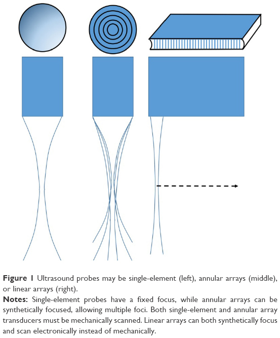 | Figure 1 Ultrasound probes may be single-element (left), annular arrays (middle), or linear arrays (right). |
Arrays can be either linear or annular. A linear array consists of many individual transducer elements spaced one wavelength or less apart. By introducing precise time delays in the excitation of individual piezoelectric elements (beamforming), a converging wavefront can be formed from the individual emissions, effectively producing a focused ultrasound beam in the azimuthal plane in which the elements are aligned. A cylindrical acoustic lens is used to create a fixed focus in the elevation axis normal to the azimuthal plane. Synthetic focusing allows the array’s focal length in the azimuthal plane to be varied at will or even to create multiple focal zones in one image to provide an extended depth-of-field. Linear arrays also provide a faster scan rate than single-element sector probes because scanning is performed electronically rather than mechanically. As frequency increases, however, the array elements must be made smaller (as wavelength, λ = c/υ, where c = speed of sound and υ = frequency) and they and associated electronics packed more and more tightly together, making fabrication difficult and expensive.
An annular array consists of a series of concentric transducer elements. In annular arrays, far fewer elements are required than in linear arrays, facilitating fabrication of high-frequency probes. Ketterling et al developed prototype 5-element 20 and 40 MHz annular arrays for ophthalmic imaging as an intermediate step between single-element probes and linear arrays.2 As in linear arrays, computer-controlled synthetic focusing by precise control of the timing of excitation and reception from each element provides a significant improvement in depth-of-field. However, because of the annular arrangement, synthetic focusing is only along the beam axis and the probe must still be mechanically scanned to obtain a B-scan. The requirement for mechanical scanning makes this configuration no faster in imaging speed than single-element probes, but the simple design in comparison to linear arrays and axial symmetry of the beam profile offer attractive characteristics for imaging the eye.
Resolution
Focusing is required to provide a clinically useful resolution. In general, resolution improves as frequency increases due to the inverse relationship between λ and υ. However, although an ultrasound transducer has a single nominal frequency, for example, 10 MHz, it actually emits energy over a range of frequencies, for example, 7–13 MHz, peaking at or near the nominal center frequency. This range is referred to as the transducer’s bandwidth. As bandwidth increases, the temporal duration and axial length of the acoustic pulse decrease. Wavelength imposes a limit to this process because an acoustic pulse must comprise at least one complete cycle of compression and rarefaction. “Axial resolution” refers to how close together two reflectors can be along the direction of acoustic propagation while still being distinguishable from each other. Axial resolution is computed as cL/2, where L is pulse duration. As bandwidth increases, pulse duration decreases and axial resolution improves. “Lateral resolution” refers to the ultrasound system’s ability to distinguish two reflectors positioned next to each other with respect to the ultrasound beam axis. This characteristic is affected by both frequency and focal properties. Lateral resolution in the focal plane is computed as fλ, where f is the focal ratio (focal length/aperture). As f decreases, the transducer becomes more highly focused. Lateral resolution will be greatest in the focal plane of the transducer and will increase as f decreases. With decreasing f, however, the region along the beam axis in which the transducer is well focused (depth-of-field) becomes smaller. For low f-values, lateral resolution degrades rapidly outside of this focal zone.
Imaging modes
There are two principle modes in which diagnostic ultrasound is utilized in ophthalmology: A- and B-scans.
A-scan
In the A-scan, the transducer emits an ultrasound pulse and the range to reflectors is determined based on the time interval between pulse transmission and echo return and the known tissue speed of sound values, very much as in Langevin’s echo-location technique. A-scans are displayed as a plot of echo amplitude as a function of range. A-scan of the eye was described by Mundt and Hughes3 and Oksala and Lehtinen4 in the 1950s. Jansson, Begui, and Oksala and Lehtinen made crucial measurements of the speed of sound in ocular tissues, including cataractous lenses.5–9 By the mid-1960s, Coleman and Carlin had developed the first A-mode system for clinical axial length determination.10
Given a known speed of sound value, the range to an echo is simply cΔt/2, where Δt represents the time interval between pulse generation and echo reception. The factor of 2 is required because we must consider both the travel time of the pulse to the reflector and the time for the reflection to return to the transducer. As the speed of sound in the eye averages ~1,532 m/s, if we consider the distance to the orbital apex to be ~5 cm from the eye surface, then the maximum travel time is ~65 μs. Thus, for imaging the eye out to the orbital apex, the minimum interval between successive A-scan measurements cannot be much <0.1 ms, as we must wait for all echoes to return before launching the next pulse. As pulse duration is only a few nanoseconds, the transducer spends little time actually transmitting and most of its duty cycle is spent waiting passively for echo reception.
A-scan was utilized in many early studies for characterization of ocular pathologies, especially intraocular foreign bodies.11–13 An entire A-scan-based methodology called “standardized echography” was developed by Ossoinig for identifying and differentiating pathologies, including retinal detachment, vitreous membranes, hemorrhage, and tumors on the basis of A-scan patterns and amplitudes in relation to a tissue reflective standard.14 Nevertheless, the primary impact of the A-scan has been in axial length determination.
The parallel development of biocompatible lens implants, phacoemulsification, and A-scan biometry enabled the widespread adoption of surgical cataract removal plus intraocular lens (IOL) implantation to treat cataracts, which had been a major cause of blindness and still remains the primary cause of blindness outside the developed world. Significant advances in cataract surgery were contemporaneous with the development of the A-scan: Howard Ridley, a British ophthalmologist, noticed that intraocular fragments of shattered acrylic Second World War fighter canopies were often well tolerated and he developed the first IOL from this material.15 Phacoemulsification, in which the cataract is broken into fragments by ultrasound energy, was developed by Charles Kelman approximately 1967.16 In order to determine the optical refractive power of an IOL, however, one needs to know both corneal curvature and axial length. Prior to the advent of ultrasound determination of axial length, IOL power was estimated using the formula P=18+1.25D, where D is the preoperative refractive error in diopters. This method resulted in half of the patients having a postsurgical refractive error of 1D or more, and sometimes much more. Ultrasound A-scan supplied the missing piece enabling calculation of the required refractive power of an IOL so that its focus would fall on the macula and an optimal postoperative visual outcome would be achieved. In the 1970s, several investigators developed theoretical formulae for the calculation of IOL power by relating refractive outcome to presurgical values of axial length, corneal curvature, and in some cases anterior chamber depth.17–21 In contrast, the SRK (Sanders-Retzlaff-Kraft) formula is an empirically derived regression equation fitting postsurgical refractive outcomes to axial length and keratometry.22,23 Many of these formulae have been modified over the years to yield increasing accuracy in IOL powering.
A-scan measurement of axial length (Figure 2) may be performed in either a contact or immersion exam. In the contact exam, a topical anesthetic drop is applied to the eye and the probe, which has a coaxial fixation light, is gently brought into contact with the central cornea. Modern systems automatically produce on the order of thousands A-scans/second and can recognize and acquire a set of data when the probe is appropriately aligned along the visual axis. Immersion exams involve insertion of a scleral shell, which simultaneously keeps the eyelids open and allows formation of a fluid medium over the eye into which the probe is placed and data similarly acquired, but without touching the cornea. The immersion technique is more complex, but is regarded as the gold standard because there is no concern that the measurement might be affected by indentation of the cornea that might occur in a contact exam. Commercial A-scan systems include software implementing one or more lens powering formulae.
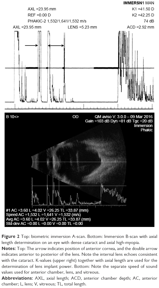 | Figure 2 Top: biometric immersion A-scan. Bottom: Immersion B-scan with axial length determination on an eye with dense cataract and axial high-myopia. |
Corneal pachymetry is also performed by A-scan. Ultrasound pachymeters (or sometimes “pachometers”24) operate at 20–50 MHz, significantly higher in frequency than axial length probes, and are designed to measure central corneal thickness in a contact exam. Higher frequency probes can also measure the thickness of corneal layers, including the epithelium. The probes are lightweight, handheld, and battery powered and so cables are avoided. Some systems support wireless data communication. The chief drawback of handheld pachymetry is that it is a point measurement. While pachymetry can be performed outside the central zone, positional reproducibility is always a factor.
B-scan
The second major ophthalmic ultrasound mode is the B-scan, initially developed in 1958 by Baum and Greenwood25 and followed soon thereafter by others.26,27 In B-mode (Figure 3), the focused, single-element ultrasound transducer is mechanically pivoted while pulsing and receiving at a series of angular increments to sweep out a sector. From the orientation of the probe at each moment and the range to each echo, a two-dimensional image of the eye, a B-scan, can be generated by setting pixel brightness at each position proportional to echo amplitude. B-scan requires a means for ascertaining transducer orientation, such as a positional encoder incorporated into the motion system. In the 1960s, Coleman et al28 and Purnell29 separately developed immersion B-scan systems in which a normal saline bath was formed between the eye and the transducer, allowing the transducer to be mechanically moved without touching the eye to produce B-scans. The first enclosed B-scan probe for contact ultrasound examination of the eye was developed by Holasek et al.30 Shortly thereafter, Bronson31 developed a contact B-scan that became the prototype of clinical systems to follow. While early analog technology used storage oscilloscopes and Polaroid cameras for screen capture, modern systems are fully digital. Current commercial ophthalmic B-scan systems typically produce approximately ten images per second and allow storage of real-time “cineloops” as well as individual images. Such systems also incorporate biometry modules, which can be used for the measurement of the dimensions of space-occupying lesions, such as tumors and cysts as well as other structures. In certain instances where A-scan biometry is unreliable, such as in an irregular staphylomatous globe, axial length can be determined by immersion B-scan (Figure 2, bottom).
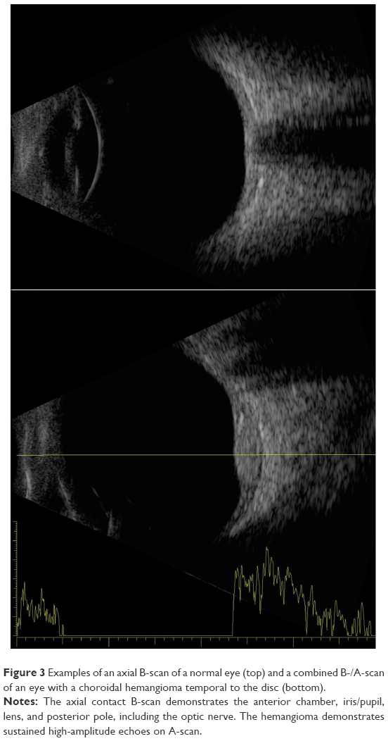 | Figure 3 Examples of an axial B-scan of a normal eye (top) and a combined B-/A-scan of an eye with a choroidal hemangioma temporal to the disc (bottom). |
Just as the corneal pachymeter is a high-frequency adaptation of A-mode, ultrasound biomicroscopy (UBM) is a high-frequency B-scan modality. In 1989, Sherar and Foster described fabrication of polymer transducers with frequencies of up to 100 MHz32 and demonstrated a prototype B-scan system with ex vivo images of the eye.33 Clinical application was first described by Pavlin et al in the early 1990s.34,35 Because wavelength is inversely related to frequency, higher frequencies provide better resolution (wavelength ≈150 μm at 10 MHz versus 30 μm at 50 MHz). Unfortunately, absorption increases exponentially with frequency. Even the vitreous, which is 99% water, significantly attenuates ultrasound in the UBM frequency range, preventing its use for retinal imaging. As a consequence, UBM is only applicable to the anterior segment.
Because of attenuation by the eyelid, UBM exams are performed with open lids after administration of topic anesthetic drops. Unlike 10 MHz probes, UBM probes are not sealed, that is, the transducer is exposed during scanning, necessitating a means for fluid standoff between the transducer and the eye. The exam may be performed using a scleral shell, and this is still used by many; however, disposable water-filled bubble tips are now available to place over the front of the probe. During the exam, the thin polyethylene membrane of the bubble-tip is placed in contact with the surface of the eye, providing sufficient flexibility for adjusting position, orientation, and range to image all anterior segment structures. Figure 4 provides examples of UBM images, and Figure 5 demonstrates a combined 10 MHz and UBM exam.
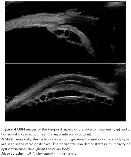 | Figure 4 UBM images of the temporal aspect of the anterior segment (top) and a horizontal cross-section near the angle inferiorly (bottom). |
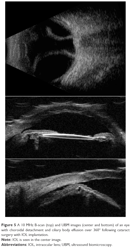 | Figure 5 A 10 MHz B-scan (top) and UBM images (center and bottom) of an eye with choroidal detachment and ciliary body effusion over 360° following cataract surgery with IOL implantation. |
A unique technology for anterior segment imaging and biometric analysis of the cornea is the Artemis system, introduced in the early 2000s as a commercial outgrowth of work by Silverman et al.36 The Artemis uses a disposable eyepiece to form a normal saline coupling medium between the 35 MHz transducer and the eye. The instrument moves the transducer in an arc so that the beam axis maintains approximate normality to the surface of the cornea during scanning, which allows acquisition of data over the full corneal diameter. (A conventional sector or linear scan geometry limits data to the central 3 mm zone because of the specularity of the corneal surfaces and the limited depth-of-field of UBM transducers.) In addition, the instrument provides a fixation light and infrared camera for visualization of the eye during scanning. By performing a series of scans at successive clock hours, and measuring the thickness of the epithelium and stroma at each position, maps of the thickness of each layer (including the flap in laser-assisted in situ keratomileusis-treated eyes) can be generated. A noteworthy accomplishment achieved by Reinstein et al using this device was the first documentation of epithelial remodeling following ablative corneal refractive surgery (where epithelial thickening over the ablated zone occurs)37 and in keratoconus (where epithelial thinning over the apex occurs).38 An updated version of this technology, the Insight-100, was recently introduced by Arcscan, Inc. (Golden, CO, USA) and a representative B-scan and series of pachymetric maps on a laser-assisted in situ keratomileusis-treated eye are provided in Figure 6.
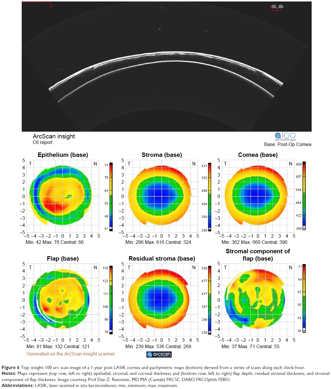 | Figure 6 Top: insight-100 arc scan image of a 1-year post-LASIK cornea and pachymetric maps (bottom) derived from a series of scans along each clock-hour. |
Surprisingly, probes offering frequencies intermediate between standard 10 MHz and UBM (≥35 MHz) did not become available until about 2004, when reports by Coleman et al and Hewick et al described the advantages of newly introduced 20 MHz probes for retinal imaging.39,40 As would be expected, 20 MHz probes offer superior resolution with respect to 10 MHz probes (Figure 7), and are thus useful for detailed examination of the retina and optic nerve head. Although they provide sufficient penetration to examine the anterior orbital structures (muscles, optic nerve, etc), attenuation limits their capacity to penetrate deeply into the orbit, and low-intensity scatterers within the vitreous are better depicted at 10 MHz. Probes at this frequency are now available in commercial systems.
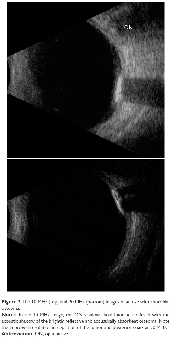 | Figure 7 The 10 MHz (top) and 20 MHz (bottom) images of an eye with choroidal osteoma. |
Optical coherence tomography versus ultrasound
Optical coherence tomography (OCT) of the retina was introduced by Huang et al.41 OCT is in many respects an optical analog of ultrasound and even shares its nomenclature (A- and B-scans), but is based on detection of reflected light by optical interferometry. Because light scattering and reflection result from the presence of discontinuities in refractive index, OCT images have an overall similar appearance to ultrasound images, which depict acoustic impedance discontinuities. But, because optical wavelengths are much shorter than ultrasound wavelengths and because light can be better collimated and focused, finer axial and lateral resolution can be achieved by OCT.
While early OCT systems used time-domain methods that required mechanical scanning in the range axis, modern systems are either spectral domain (using a broadband light source, grating, and line scan camera to acquire the backscatter spectrum along each line-of-sight, eliminating the need for mechanical scanning)42 or swept-source (where the light source itself sweeps through a range of frequencies to allow acquisition of the reflectance spectrum).43,44 These advances in OCT technology have allowed introduction of high-speed instruments producing images with sufficient sensitivity and resolution to evaluate the retinal layers and choroid. Many OCT systems include optics for evaluation of the anterior segment. Recently introduced OCT-angiography allows visualization of retinal capillary networks without the need to inject dye.45
OCT is advantageous because it is noncontact, high-resolution, high speed, and can be performed in the context of a real-time en face image of the retina so that there is no question where the image is from anatomically. Three-dimensional scanning is readily achieved. Because of these characteristics, OCT is the method of choice for retinal examination. Ultrasound, however, retains its importance for imaging wherever light cannot reach, such as the orbit, pigmented tumors, the retro-iridal space, and the ciliary body or where media are optically opaque due to corneal scarring, cataract, or hemorrhage. Optical interferometry is also now widely used for axial length measurement, but where cataracts are dense, A-mode ultrasound is performed. Ultrasound is also advantageous for imaging the vitreous in a kinetic exam, in which voluntary saccades allow assessment of organization and traction where hemorrhage, membranes, posterior vitreous detachment, or retinal detachment are present. This is not possible in OCT as scanning must be performed through the pupil.
High-intensity focused ultrasound
At high intensity, ultrasound can produce significant biologic effects through cavitation and thermal mechanisms. Diagnostic ultrasound instrumentation is designed to avoid such effects. In fact, the US Food and Drug Administration (FDA) 510k standard for ophthalmic ultrasonography46 is more stringent than for any other anatomic site. Substantial research, however, has been performed on the application of high-intensity ultrasound to produce therapeutic effects in the eye. Coleman et al and Lizzi et al developed a system for generation of high-intensity focused ultrasound (HIFU) in the late 1970s47–49 and investigated applications, including repair of lens capsular tears,50 accelerated resorption of vitreous hemorrhage,51 treatment of retinal detachment,52 and treatment of uveal melanoma in conjunction with brachytherapy.53–55 However, the primary clinical application of HIFU in ophthalmology is treatment of glaucoma. HIFU treatment of glaucoma is an ablative technique in which the ultrasound beam is focused on the ciliary body. The HIFU transducer assembly developed by Lizzi and Coleman included an 80 mm diameter focused piezoelectric element for generation of HIFU, a diagnostic transducer for ranging, and a coaxial light beam for aiming. In general, six circumferential spots located 1 mm posterior to the limbus were treated with 5-second long exposures of continuous focused ultrasound, producing thermal damage in the ciliary body. Experimental preclinical and clinical findings demonstrated significant reduction in intraocular pressure following treatment, presumably due to impairment of aqueous production and possibly enhancement of transscleral outflow.56–59 A commercial system, the Sonocare CST-100, was developed and a multicenter study performed confirming its safety and efficacy.60,61 While the Sonocare system, which was the first FDA-approved HIFU device in any clinical specialty,62 was ultimately commercially unsuccessful due to the contemporaneous introduction of laser surgery and improved medical therapy, HIFU techniques for glaucoma treatment continue to be investigated.63,64
Unfocused ultrasound
While it would seem intuitively obvious that ultrasound must be focused to create useful diagnostic images, a recently developed linear array-based technology called “compound coherent plane-wave imaging” produces B-mode images at ultrafast rates using unfocused ultrasound. In conventional linear arrays, subgroups of elements produce a focused beam that is scanned back-and-forth from one end of the array to the other to produce B-mode images. In plane-wave imaging, all array elements fire at once to produce one, unfocused wavefront, and focusing is achieved by processing of digitized echo data.65 This is accomplished iteratively for each image pixel position by introducing appropriate time delays to echo data received by each array element and summing, which is precisely the inverse of how arrays conventionally produce a focused beam on transmit. While computationally intensive, this inverse beamforming process can be readily accomplished in real-time with appropriate instrumentation and software.
Compounding consists of emitting plane-waves at a series of angles and combining echo data received from each angle to form a final compound image. Compounding improves both lateral resolution and signal-to-noise ratio. However, the rate at which compounded images are generated is inversely proportional to the number of angles.
Because plane-wave images are formed with each excitation, a speedup in imaging rate of two orders of magnitude compared to conventional linear arrays and three orders of magnitude compared to mechanically scanned probes is achievable, making it ideal for imaging blood flow and other transient motions. Also, because the emitted ultrasound is unfocused, acoustic intensity is significantly reduced compared to that of a conventionally focused linear array. This factor is of particular significance in ophthalmology because focused Doppler systems typically exceed FDA ophthalmic regulatory guidelines.46 Ultrafast plane-wave technology, plus the recent introduction of linear arrays of 15 MHz and above, brightens the prospect for improved and more capable systems for ultrasound imaging of the eye, especially visualization and measurement of flow. We recently reported on the use of this technique to image the eye at up to 20,000 B-scans per second with an 18 MHz linear array at intensities well within FDA guidelines, demonstrating depiction and measurement of flow in the major orbital vessels and the choroid both in real-time and, with higher resolution and sensitivity, in postprocessed data.66 Examples of compound plane-wave images depicting anatomy and blood flow in the region of the posterior pole are provided in Figure 8. This emerging technology offers the promise of a safe and effective means for imaging blood flow in neoplasms, vascular malformations, and in the choroid, orbital vessels, and anterior segment in diseases where perfusion may play a significant role in pathogenesis and progression, including diabetic retinopathy, glaucoma, maculopathies, and retinopathy of prematurity.
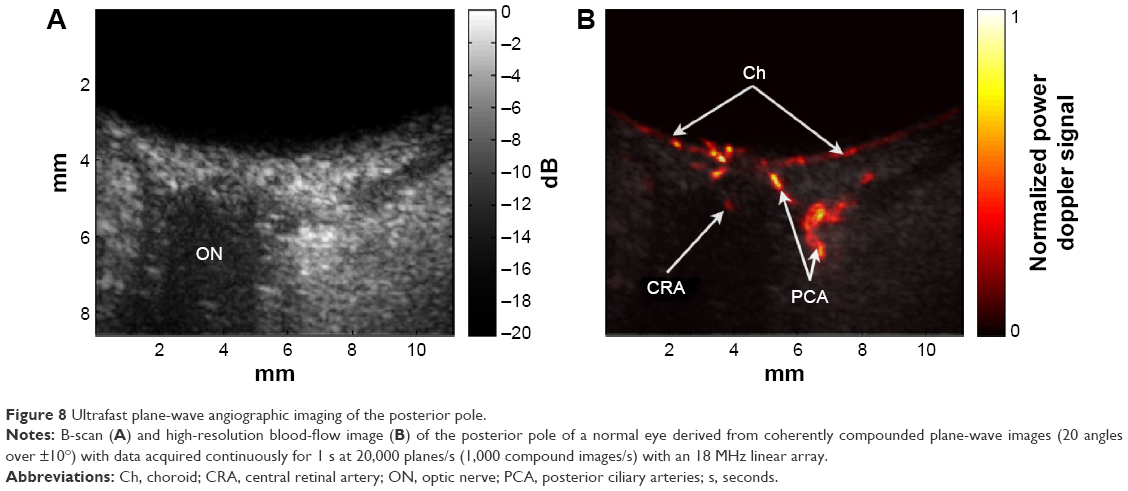 | Figure 8 Ultrafast plane-wave angiographic imaging of the posterior pole. |
Conclusion
While focused ultrasound imaging of the eye is a mature technology, continuous advances in instrumentation, transducer design, computational power, and signal-processing are opening new avenues for improvement in imaging and therapeutic intervention. The introduction of ultrafast plane-wave systems in particular heralds an era in which ocular blood flow will be depicted and measured at safe intensities, opening a new and heretofore closed window for understanding disease mechanisms and improving clinical management.
Acknowledgments
This review was supported in part by an NIH grant R01 EY025215 and an unrestricted grant to the Department of Ophthalmology of the Columbia University Medical Center from Research to Prevent Blindness.
Disclosure
Dr Silverman has a commercial interest in Arcscan, Inc. The author has no other conflicts of interest to declare.
References
Panda PK. Review: environmental friendly lead-free piezoelectric materials. J Mater Sci. 2009;44(19):5049–5062. | ||
Ketterling JA, Aristizábal O, Turnbull DH, Lizzi FL. Design and fabrication of a 40-MHz annular array transducer. IEEE Trans Ultrason Ferroelectr Freq Control. 2005;52(4):672–681. | ||
Mundt G, Hughes W. Ultrasonics in ocular diagnosis. Am J Ophthalmol. 1956;41(3):488–498. | ||
Oksala A, Lehtinen A. Diagnostic value of ultrasonics in ophthalmology. Ophthalmologica. 1957;134(6):387–395. | ||
Jansson F, Sundmark E. Determination of the velocity of ultrasound in ocular tissues at different temperatures. Acta Ophthalmol (Copenh). 1961;39(5):899–910. | ||
Jansson F, Kock E. Determination of the velocity of ultrasound in the human lens and vitreous. Acta Ophthalmol (Copenh). 1962;40(4):420–433. | ||
Jansson F. Measurements of intraocular distances by ultrasound. Acta Ophthalmol Suppl. 1963;74(Suppl):1–51. | ||
Begui ZE. Acoustic properties of the refractive media of the eye. J Acoust Soc Am. 1954;26:365–368. | ||
Oksala A, Lehtinen A. Measurement of the velocity of sound in some parts of the eye. Acta Ophthalmol (Copenh). 1958;36(4):633–639. | ||
Coleman DJ, Carlin B. A new system for visual axis measurements in the human eye using ultrasound. Arch Ophthalmol. 1967;77(1):124–127. | ||
Penner R, Passmore JW. Magnetic vs nonmagnetic intraocular foreign bodies: an ultrasonic determination. Arch Ophthalmol. 1966;76(5):676–677. | ||
Cowden JW, Runyan TE. Localization of intraocular foreign bodies: further experiences in ultrasonic vs radiologic methods. Arch Ophthalmol. 1969;82(3):299–301. | ||
Bronson NR. Techniques of ultrasonic localization and extraction of intraocular and extraocular foreign bodies. Am J Ophthalmol. 1965;60(4):596–603. | ||
Ossoinig K. Clinical echo-ophthalmology. In: Blodi FC, editor. Current Concepts of Ophthalmology. Vol III. St Louis, MO: CV Mosby Co; 1972:101–130. | ||
Apple D. Sir Harold Ridley and His Fight for Sight: He Changed the World So That We May Better See It. Thorofare, NJ: Slack Incorporated; 2006. | ||
Linebarger EJ, Hardten DR, Shah GK, Lindstrom RL. Phacoemulsification and modern cataract surgery. Surv Ophthalmol. 1999;44(2):123–147. | ||
Thijssen JM. The emmetropic and iseikonic implant lens: computer calculation of the refractive power and its accuracy. Ophthalmologica. 1975;171(6):467–486. | ||
Colenbrander MC. Calculations of the power of an iris clip lens for distance vision. Br J Ophthalmol. 1973;57(10):735–740. | ||
Fyodorov SN, Galin MA, Linksz A. Calculation of the optical power of intraocular lens. Invest Ophthalmol. 1975;14(8):625–628. | ||
Binkhorst RD. The optical design of intraocular lens implants. Ophthal Surg. 1975;6(3):17–31. | ||
Hoffer KJ. Accuracy of ultrasound intraocular lens calculation. Arch Ophthalmol. 1981;99(10):1819–1823. | ||
Sanders DR, Kraff MC. Improvement of intraocular lens power calculation using empirical data. Am Intra-Ocular Implant Soc J. 1980;6(3):263–267. | ||
Sanders DR, Retzlaff J, Kraff MC. Comparison of empirically derived and theoretical aphakic refraction formulas. Arch Ophthalmol. 1983;101(6):965–967. | ||
Aslanides IM, Aslanides MN, Reinstein DZ, Silverman RH, Coleman DJ. Have you ever seen a pachoderm? J Refract Surg. 1995;11(3):162–164. | ||
Baum G, Greenwood I. The application of ultrasound locating techniques to ophthalmology. Part I: reflective properties. Am J Ophthalmol. 1958;82:475–479. | ||
Baum G, Greenwood I. Ultrasonography: an aid in orbital tumor diagnosis. Arch Ophthalmol. 1960;64:180–194. | ||
Baum G. Use of ultrasonography in the differential diagnosis of ocular tumors. In: Boniuk M, editor. Ocular and Adnexal Tumors. St Louis, MO: CV Mosby Co; 1964:308–321. | ||
Coleman DJ, Kong WF, Katz I. A hand-operated ultrasound scan system for ophthalmic evaluation. Am J Ophthalmol. 1969;68(2):256–263. | ||
Purnell EW. Ultrasound in ophthalmological diagnosis. In: Grossman CC, Joseph HH, Joyner C, editors. Diagnostic Ultrasound: Proceedings of 1st International Conference of University of Pittsburgh. New York: Plenum Press; 1965:95–110. | ||
Holasek E, Sokollu A, Purnell EW. A digitized, direct contract B-scanner for ophthalmic application. J Clin Ultrasound. 1973;1(1):36–40. | ||
Bronson NR. Development of a simple B-scan ultrasonoscope. Trans Am Ophthalmol Soc. 1972;70:365–408. | ||
Sherar MD, Foster FS. The design and fabrication of high frequency poly (vinylidene fluoride) transducers. Ultrason Imaging. 1989;11(2):75–94. | ||
Sherar MD, Starkoski BG, Taylor WB, Foster FS. A 100 MHz B-scan ultrasound backscatter microscope. Ultrason Imaging. 1989;11(2):95–105. | ||
Pavlin CJ, Sherar M, Foster FS. Subsurface ultrasound microscopic imaging of the intact eye. Ophthalmology. 1990;97(2):244–250. | ||
Pavlin CJ, Harasiewicz K, Sherar MD, Foster FS. Clinical use of ultrasound biomicroscopy. Ophthalmology. 1991;98(3):287–295. | ||
Silverman RH, Reinstein DZ, Raevsky T, Coleman DJ. Improved system for ultrasonic imaging and biometry of the cornea. J Ultra Med. 1997;16:117–124. | ||
Reinstein DZ, Silverman RH, Raevsky T, et al. Arc-scanning very high-frequency ultrasound for 3-D pachymetric mapping of the corneal epithelium and stroma in laser in situ keratomileusis. J Refract Surg. 2000;16(4):414–430. | ||
Reinstein DZ, Gobbe M, Archer TJ, Silverman RH, Coleman DJ. Epithelial, stromal, and total corneal thickness in keratoconus: three-dimensional display with artemis very-high frequency digital ultrasound. J Refract Surg. 2010;26(4):259–271. | ||
Coleman DJ, Silverman RH, Chabi A, et al. High resolution ultrasonic imaging of the posterior segment. Ophthalmology. 2004;111(7):1344–1351. | ||
Hewick SA, Fairhead AC, Culy JC, Atta HR. A comparison of 10 MHz and 20 MHz ultrasound probes in imaging the eye and orbit. Br J Ophthalmol. 2004;88(4):551–555. | ||
Huang D, Swanson EA, Lin CP, et al. Optical coherence tomography. Science. 1991;254(5035):1178–1181. | ||
de Boer JF, Cense B, Park BH, Pierce MC, Tearney GJ, Bouma BE. Improved signal-to-noise ratio in spectral-domain compared with time-domain optical coherence tomography. Opt Lett. 2003;28(21):2067–2069. | ||
Chinn SR, Swanson EA, Fujimoto JG. Optical coherence tomography using a frequency-tunable optical source. Opt Lett. 1997;22(5):340–342. | ||
Potsaid B, Baumann B, Huang D, et al. Ultrahigh speed 1050 nm swept source/Fourier domain OCT retinal and anterior segment imaging at 100,000 to 400,000 axial scans per second. Optics Express. 2010;18(19):20029–20048. | ||
Spaide RF, Klancnik JM Jr, Cooney MJ. Retinal vascular layers imaged by fluorescein angiography and optical coherence tomography angiography. JAMA Ophthalmol. 2015;133(1):45–50. | ||
Food and Drug Administration, US Department of Health and Human Services. Information for Manufacturers Seeking Marketing Clearance of Diagnostic Ultrasound Systems and Transducers. Rockville, MD: Center for Devices and Radiological Health; 2008. | ||
Lizzi FL, Coleman DJ, Driller J, Franzen LA, Jakobiec FA. Experimental, ultrasonically induced lesions in the retina, choroid, and sclera. Invest Ophthalmol Vis Sci. 1978;17(4):350–360. | ||
Lizzi FL, Packer AJ, Coleman DJ. Experimental cataract production by high frequency ultrasound. Ann Ophthalmol. 1978;10(7):934–942. | ||
Coleman DJ, Lizzi FL, Jakobiec FA. Therapeutic ultrasound in the production of ocular lesions. Am J Ophthalmol. 1978;86(2):185–192. | ||
Coleman DJ, Lizzi FL, Torpey JH, et al. Treatment of experimental lens capsular tears with intense focused ultrasound. Br J Ophthalmol. 1985;69(9):645–649. | ||
Lucas BC, Driller J, Iwamoto T, Silverman RH, Lizzi FL, Coleman DJ. Ultrasonically induced disruption and hemolysis of vitreous hemorrhage. Ultra Med Biol. 1989;15:29–37. | ||
Rosecan LR, Iwamoto T, Rosado A, Lizzi FL, Coleman DJ. Therapeutic ultrasound in the treatment of retinal detachment: clinical observations and light and electron microscopy. Retina. 1985;5(2):115–122. | ||
Lizzi FL, Driller J, Lunzer B, Kalisz A, Coleman DJ. Computer model of ultrasonic hyperthermia and ablation for ocular tumors using B-mode data. Ultra Med Biol. 1992;18(1):59–73. | ||
Coleman DJ, Lizzi FL, Burgess SEP, et al. Ultrasonic hyperthermia and radiation in the management of intraocular malignant melanoma. Am J Ophthalmol. 1986;101(6):635–642. | ||
Coleman DJ, Silverman RH, Iwamoto T, et al. Histopathologic effects of ultrasonically induced hyperthermia in intraocular malignant melanoma. Ophthalmology. 1988;95(7):970–981. | ||
Coleman DJ, Lizzi FL, Driller J, et al. Therapeutic ultrasound in the treatment of glaucoma. I. Experimental model. Ophthalmology. 1985;92(3):339–346. | ||
Burgess SE, Iwamoto T, Coleman DJ, Lizzi FL, Driller J, Rosado A. Histologic changes in porcine eyes treated with high-intensity focused ultrasound. Ann Ophthalmol. 1987;19(4):133–138. | ||
Polack PJ, Iwamoto T, Silverman RH, Driller J, Lizzi FL, Coleman DJ. Histologic effects of contact ultrasound for the treatment of glaucoma. Invest Ophthalmol Vis Sci. 1991;32(7):2136–2142. | ||
Coleman DJ, Lizzi FL, Driller J, et al. Therapeutic ultrasound in the treatment of glaucoma: II. Clinical applications. Ophthalmology. 1985;92(3):347–353. | ||
Burgess SEP, Silverman RH, Coleman DJ, et al. Treatment of glaucoma with high-intensity focused ultrasound. Ophthalmology. 1986;93(6):831–838. | ||
Haut J, Colliac JP, Falque L, Renard Y. Indications and results of Sonocare (ultrasound) in the treatment of ocular hypertension. A preliminary study of 395 cases. Ophtalmologie. 1990;4(2):138–141. | ||
Muratore R. A history of the Sonocare CST-100: the first FDA-approved HIFU device. In: Clement GT, McDannold NJ, Hynynen K, editors. Therapeutic Ultrasound: 5th International Symposium Held 27–29 October 2005 in Boston, Massachusetts. AIP Conference Proceedings. Melville, NY: American Institute of Physics; 2006:508–512. | ||
Aptel F, Charrel T, Lafon C, et al. Miniaturized high-intensity focused ultrasound device in patients with glaucoma: a clinical pilot study. Invest Ophthalmol Vis Sci. 2011;52(12):8747–8753. | ||
Aptel F1, Lafon C. Treatment of glaucoma with high intensity focused ultrasound. Int J Hyperthermia. 2015;31(3):292–301. | ||
Montaldo G, Tanter M, Bercoff J, Benech N, Fink M. Coherent plane-wave compounding for very high frame rate ultrasonography and transient elastography. IEEE Trans Ultrason Ferroelectr Freq Control. 2009;56(3):489–506. | ||
Urs R, Ketterling JA, Silverman RH. Ultrafast ultrasound imaging of ocular anatomy and blood flow. Invest Ophthalmol Vis Sci. 2016;57(8):3810–3816. |
 © 2016 The Author(s). This work is published and licensed by Dove Medical Press Limited. The full terms of this license are available at https://www.dovepress.com/terms.php and incorporate the Creative Commons Attribution - Non Commercial (unported, v3.0) License.
By accessing the work you hereby accept the Terms. Non-commercial uses of the work are permitted without any further permission from Dove Medical Press Limited, provided the work is properly attributed. For permission for commercial use of this work, please see paragraphs 4.2 and 5 of our Terms.
© 2016 The Author(s). This work is published and licensed by Dove Medical Press Limited. The full terms of this license are available at https://www.dovepress.com/terms.php and incorporate the Creative Commons Attribution - Non Commercial (unported, v3.0) License.
By accessing the work you hereby accept the Terms. Non-commercial uses of the work are permitted without any further permission from Dove Medical Press Limited, provided the work is properly attributed. For permission for commercial use of this work, please see paragraphs 4.2 and 5 of our Terms.