")
Back to Journals » International Journal of Nanomedicine » Volume 14
Evaluation of a simple off-the-shelf bi-layered vascular scaffold based on poly(L-lactide-co-ε-caprolactone)/silk fibroin in vitro and in vivo
Authors Jin D, Hu J, Xia D, Liu A , Kuang H, Du J, Mo X , Yin M
Received 15 February 2019
Accepted for publication 1 May 2019
Published 7 June 2019 Volume 2019:14 Pages 4261—4276
DOI https://doi.org/10.2147/IJN.S205569
Checked for plagiarism Yes
Review by Single anonymous peer review
Peer reviewer comments 3
Editor who approved publication: Dr Mian Wang
Dawei Jin,1,* Junfeng Hu,2,* Dekai Xia,1 A’li Liu,3 Haizhu Kuang,2 Jun Du,3 Xiumei Mo,2 Meng Yin1
1Department of Cardiothoracic Surgery, Shanghai Children‘s Medical Center, School of Medicine, Shanghai Jiao Tong University, Shanghai 200127, People’s Republic of China; 2State Key Lab for Modification of Chemical Fibers and Polymer Materials, College of Chemistry, Chemical Engineering and Biotechnology, Donghua University, Shanghai 201620, People’s Republic of China; 3Imaging Diagnosis Center, Shanghai Children‘s Medical Center, School of Medicine, Shanghai Jiao Tong University, Shanghai 200127, People’s Republic of China
*These authors contributed equally to this work
Purpose: In the field of small-caliber vascular scaffold research, excellent vascular remodeling is the key to ensuring anticoagulant function. We prepared an off-the-shelf bi-layered vascular scaffold with a dense inner layer and a loose outer layer and evaluated its remodeling capabilities by in vivo transplantation.
Materials and Methods: Based on poly(L-lactide-co-ϵ-caprolactone) (PLCL), silk fibroin(SF), and heparin (Hep), PLCL/SF/Hep bi-layered scaffolds and PLCL/Hep bi-layered scaffolds were prepared by electrospinning. The inner layer was a PLCL/SF/Hep or PLCL/Hep nanofiber membrane, and the outer layer was PLCL/SF nano yarn. The in vitro tests included a hydrophilicity test, mechanical properties test, and blood and cell compatibility evaluation. The in vivo evaluation was conducted via single rabbit carotid artery replacement and subsequent examinations, including ultrasound imaging, immunoglobulin assays, and tissue section staining.
Results: Compared to the PLCL/Hep nanofiber membrane, the hydrophilicity of the PLCL/SF/Hep nanofiber membrane was significantly improved. The mechanical strength met application requirements. Both the blood and cell compatibility were optimal. Most importantly, the PLCL/SF/Hep scaffolds maintained lumen patency for 3 months after carotid artery transplantation in live rabbits. At the same time, CD31 and α-SMA immunofluorescence staining confirmed bionic endothelial and smooth muscle layers remodeling.
Conclusion: Using this hybrid strategy, PLCL and SF were combined to manufacture bi-layered small-caliber vascular scaffolds; these PLCL/SF/Hep scaffolds showed satisfactory vascular remodeling
Keywords: silk fibroin, small-caliber, vascular remodeling, hybrid strategy
Introduction
Cardiovascular diseases (CVD) especially the thrombotic events significantly threaten human life and health.1 CVD has become the leading cause of death according to the global data surveyed by the World Health Organization. Moreover, the incidence of CVD continues to rise. Thrombotic events are often treated by stent implantation2 or diseased segment(s) replacement.3 The vessels for replacement are mostly autologous,4 allogeneic,5 or artificial.6 Autologous vessels stand for their excellent compatibility but are hindered by limited source and the requirement for creating a secondary injury to harvest the replacement vessel(s). Allogeneic vessels, on the other hand, have the potential for immune rejection. By contrast, artificial scaffolds are not only rich in source but can also be easy to prepare, so they have become popular alternatives in clinical practice. At present, large-caliber artificial vascular scaffolds (greater than 6 mm) have shown a high success rate after surgery. However, the incidence of thrombus recurrence in small-caliber artificial vascular scaffolds (less than 6 mm) is still high7 and strongly related to bad vascular remodeling, especially the endothelialization and smooth muscle layer remodeling. Therefore, it is clinically urgent to fabricate an off-the-shelf small-caliber scaffold with high functionality.
Poly(L-lactide-co-ε-caprolactone) (PLCL) has been widely used in tissue engineering, but its poor hydrophilicity leads to limited cell adhesion and proliferation,8 resulting in poor or insufficient vascular remodeling. In contrast, silk fibroin (SF), a natural protein material, stands out because of its superior hydrophilicity, excellent cell compatibility, and generally safe degradation products that do no harm to the human body.9,10 However, Soffer et al prepared a tubular scaffold with a diameter of 5 mm from a fibroin solution and found that it exhibited inferior mechanical properties compared to natural blood vessels, which was determined by evaluating the tensile strength at break and burst strength.11 Clinically, ideal materials for artificial vascular scaffolds application needs to satisfy the requirements of both favorable mechanics and excellent hydrophilicity. Good mechanical properties can ensure the scaffolds will not undergo deformation, while the excellent hydrophilicity promotes the cell adhesion and proliferation on the material, which facilities necessary vascular remodeling. Theoretically, the hybrid strategy, utilizing a combination of synthetic polymers and natural materials could make up for the shortcoming of either strategy alone and be used to create a highly favorable composite material.12 Herein, we fabricated an off-the-shelf bi-layered scaffold by electrospinning technology, utilizing the mechanical strength of PLCL and the excellent hydrophilicity of SF. We conducted both in vitro and in vivo evaluations to evaluate its preliminary application.
Materials and methods
Extraction of regenerated SF
Silkworm pupa cocoons were placed in a 0.5 w/v % sodium carbonate aqueous solution. The solution was then boiled continuously for 30 mins, a total of 3 times. Then, the raw silk was cooled and washed in deionized water, then pulled loose and dried in an oven at 60°C to obtain a refined silk thread. Then, a 9.3 mol/L lithium bromide solution was used to dissolve the refined SF. The bath ratio was 100 mL lithium bromide solution to 15 g refined SF. The beaker was then cleaned and put into the rotor after drying. Then, 9.3 mol/L lithium bromide solution was poured into the beaker and placed in the water bath, the temperature was set to 60°C, and the refined silk was added to the beaker and heated for 1 hr to generate a refined silk solution. The solution was then poured into a dialysis bag (molecular weight 14,000), and the dialysis bag was placed in a container filled with deionized water and dialyzed for 72 hrs. The deionized water in the container was replaced 6 times at the same time interval. Finally, the pure refined SF solution was obtained. The pure refined SF solution was filtered and poured into a watch glass and cooled at −80°C overnight, then freeze-dried for 72 hrs in a vacuum freeze-drying oven to obtain a SF sponge.
Preparation of electrospinning solution
PLCL solids were weighed into a 10 mL beaker and hexafluoroisopropanol was added. The beaker was placed on a magnetic stirrer for one night to fully dissolve the PLCL and obtain a PLCL solution with a concentration of 10% (w/v). It was allowed to then stand to remove the air bubbles and sealed at room temperature.
SF and PLCL were weighed at a mass ratio of 25:75. PLCL and SF were dissolved in hexafluoroisopropanol under normal temperature conditions and placed on a magnetic stirrer for 24 hrs to fully dissolve and obtain a homogeneous mixture with a concentration of 10% (w/v). The solution was then allowed to stand to remove the air bubbles and sealed at room temperature.
Heparin (Hep) was weighed and placed in a small beaker. After adding deionized water, the beaker was wrapped with foil to avoid decomposition of the heparin. The beaker was placed on a magnetic stirrer for 12 hrs to allow the heparin to dissolve completely. A 15% (w/v) heparin solution was sealed and stored in a refrigerator at 4°C.
Preparation of nanofiber membranes and nano yarn membranes
Two different kinds of nanofiber membranes with shell-core structures were prepared by coaxial electrospinning. The schematic diagram of the coaxial electrospinning device is shown in Figure 1B. The principle is similar to that of ordinary electrospinning technology (Figure 1A), except the original spinneret was replaced by a coaxial spinneret needle. The PLCL or PLCL/SF solution with a concentration of 10% (w/v) as the shell solution and the heparin solution with a concentration of 15% (w/v) as the core solution were drawn each into a disposable syringe. Driven by the micro-propulsion pump, the spinning solutions converged with each other and formed PLCL/Hep or PLCL/SF/Hep nanofiber membranes. The prepared nanofiber membranes were ventilated for 2 hrs and placed in a vacuum drying oven for 1 week to evaporate the residual hexafluoroisopropanol solvent at room temperature. Spinning parameters were set as follows: the propulsion speed of PLCL or PLCL/SF was 1 mL/hr, the propulsion speed of heparin was 0.2 mL/hr, the high-voltage DC power was 14 kV, the collection distance was 12 cm, the spinning temperature was 25°C, the spinning relative humidity was 55%, and the electrospinning time was 5 hrs.
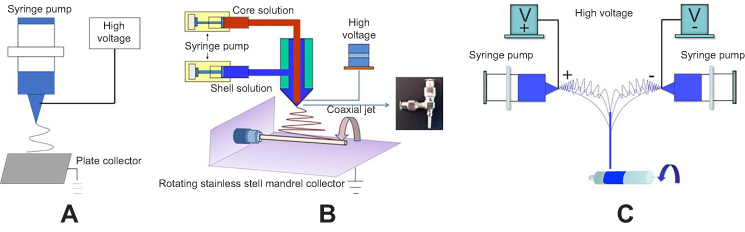 | Figure 1 The schematic diagram of different electrospinning device. (A) the ordinary electrospinning device, (B) the coaxial electrospinning device, (C) the conjugated electrospinning device. |
The loose and fiber-aligned PLCL/SF nano yarns were prepared by conjugated electrospinning. A schematic diagram of a conjugated electrospinning device is shown in Figure 1C. The face-to-face syringes were filled with 10% (w/v) PLCL and SF blend spinning solution. A 9-gauge metal spinneret was used to connect the positive and negative DC voltages to the spinnerets. Two spinning fluids with opposite charges were pushed out and finally formed a PLCL/SF nano yarn with the help of a smooth rotating mandrel with a 15 cm diameter. Spinning parameters were set as follows: the propulsion speed was 0.5 mL/hr, the voltage was +10 kV or −10 kV, the distance was 15 cm, the rotation speed was 350 rpm, the spinning temperature was 25°C, the spinning humidity was 55%, and the electrospinning time was 2.5 hrs.
Preparation of bi-layered tubular scaffolds
Coaxial electrospinning was used to form the inner layer, whereas conjugated electrospinning was used to form the outer layer of the scaffolds. A smooth rotating mandrel with a diameter of 2.5 mm was used as the receiving device. Finally, the PLCL/SF/Hep scaffolds (with PLCL/SF/Hep nanofiber membrane and PLCL/SF nano yarn) and the PLCL/Hep scaffolds (with PLCL/Hep nanofiber membrane and PLCL/SF nano yarn) were obtained.
Morphology characterization of PLCL/SF/Hep scaffolds
A digital camera (Casio EX-Z 750) was used to take macro shots. The microscopic morphology of cross-sections was used to characterize the surface of the nanofiber membrane and the nano yarn by scanning electron microscopy (SEM) (Phenom XL, Phenom-World B.V., Netherlands). The nanofiber membrane and nano yarn were cut into identically sized squares and attached to the stage and sputter coated. The vacuum degree, electric current, and sputter coating time were 6 mmHg, 10 mA, and 50 s, respectively. Finally, the cross-section, nanofiber membrane, and nano yarn were observed by SEM at an accelerating voltage of 10 kV.
The internal structure of the coaxial nanofibers was observed by transmission electron microscopy (TEM). In the coaxial electrospinning process, nanofibers were collected through a copper mesh coated with a carbon film. A H-800 TEM system with an accelerating voltage of 100 kV was used to obtain the shell-core structure of a single nanofiber.
Hydrophilicity test
The difference in hydrophilicity of the materials was tested by a contact angle tester (OCA40, Dataphysics, German). The different materials were cut into identically sized squares and pasted on coverslips. A 0.03 mL drop of deionized water was placed on the surface. Then, we measured and recorded the contact angle at the steady state of the droplets. Each sample was measured three times and averaged. The differences in the hydrophilicity were compared using the contact angle.
Mechanical properties test
We used a Vernier caliper to measure the outer and inner diameter of the tubular scaffold. Each sample was measured a total of 5 times.
Samples with a length of 6 cm were taken for axial tensile testing and samples with a length of 1 cm were taken for radial tensile testing. The scaffolds were soaked in PBS for 24 hrs before the test and filter paper was then used to remove the PBS solution. Mechanical property tests were performed on a universal material testing machine (H5K-S, Hounsfield, UK). After the samples were clamped and stabilized, they were stretched at a tensile speed of 100 mm/min. Five identical scaffolds were tested 5 times each.
Heparin release assay
PLCL/SF and PLCL nanofiber membranes loaded with heparin (with a concentration of 15% (w/v)) were suspended in PBS (pH 7.4) in sealed 6-well plates. Three samples for each group, each weighing 100±5 mg, were each soaked in 3.0 ml PBS (pH 7.4). Samples were incubated under static conditions at 37°C in the presence of 5% CO2. At various time points, 1.0 mL of supernatant was retrieved from the wells, and an equal volume of fresh medium was replaced. The concentration of each retrieved heparin solution was then determined by toluidine blue method. Toluidine blue (3.0 mL) was added to the supernatant retrieved from the wells and reacted adequately with heparin for 2 hrs at 37°C. Hexane (3.0 mL) was then added and stirred vigorously to separate the heparin-toluidine blue complex formed. The aqueous solution of the samples was tested at 630 nm using an Agilent UV-Vis spectrophotometer (WFH-203B, PerkinElmer, USA).
Blood compatibility evaluation
Plasma re-calcification
We obtained fresh blood from healthy New Zealand white rabbits by jugular vein extraction and mixed the blood with 3.8% (w/v) sodium citrate at a ratio of 9:1 to acquire anticoagulated blood. Fresh anticoagulated blood was centrifuged for 20 mins at 4°C and 3000 rpm. We extracted the supernatant gently to obtain platelet-free plasma (PPP).
We placed the PLCL/SF/Hep and PLCL/Hep nanofiber membranes in a 24-well plate and cross-linked them by ethanol steam for 48 hrs. We then added 500 μL PPP to the wells after ventilation and incubated the plate in a shaker for 1 hr at 37°C. We drew 100 μL PPP from the sample wells into a 96-well plate after incubation and added 100 μL fresh CaCl2 (0.025 mol/L). We extracted five times from each sample well. In the positive and negative control group, the empty well plate was incubated with PPP, with and without CaCl2 solution, respectively. The other operations were identical. We measured the absorbance at 405 nm in the 96-well plate at 37°C using an automated microplate reader. The detection interval was 30 s, and the detection time was 45 mins.
Platelet adhesion
We drew fresh blood from jugular veins of healthy New Zealand white rabbits and mixed the collected blood with 3.8% (w/v) sodium citrate at a ratio of 9:1 to prepare fresh anticoagulated whole blood. After centrifugation at 1000 rpm and 4°C for 10 mins, the supernatant was gently withdrawn to obtain platelet-rich plasma (PRP). Then, we placed the PLCL/SF/Hep and PLCL/Hep nanofiber membranes on a 24-well plate and cross-linked them in absolute ethanol vapor for 48 h. After ventilation, the nanofiber membranes were rinsed 3 times in PBS buffer. We added freshly prepared PRP, soaked the nanofiber membrane at 37°C for 1 hr, and washed 3 times with PBS buffer. Then, we immobilized with 2.5% glutaraldehyde at 4°C for 12 hrs and dehydrated with graded alcohol. We dried the 24-well plate in a vacuum drying oven and fixed the sample on the stage. We observed the number of platelets and the adhesion morphology on the sample surface under a scanning electron microscope after sputter coating.
Cell compatibility evaluation in vitro
We cultured human umbilical vein endothelial cells (HUVECs) in Dulbecco’s modified eagle’s medium (DMEM/High Glucose) (HyClone, USA) with 10% Fetal Bovine Serum (FBS) (Biological Industries, Israel) and 1% penicillin–streptomycin (Solarbio, Beijing, China) at an atmosphere of 37°C, 5% CO2, and 95% humidity. We refreshed the medium every two days. The PLCL/SF/Hep and PLCL/Hep nanofiber membranes were received by circular coverslips with a diameter of 14 mm. The blank coverslips were used for the control. The membranes were ventilated for 2 hrs and vacuum-dried for 3 weeks to remove any residual hexafluoroisopropanol, then cross-linked and sterilized with anhydrous alcohol for 24 hrs. The membranes were then immersed in sterile PBS solution completely and rinsed for a total of 3 times. Then, the materials were soaked in DMEM/High Glucose (with 10% FBS and 1% penicillin–streptomycin) and placed in an incubator with an atmosphere of 37°C, 5% CO2, and 95% humidity for 4 hrs. HUVECs were seeded at a density of 1.0×10⁴ cells/well. The plates were kept in a cell culture incubator and we changed the medium every other day.
We performed qualitative detection of HUVECs by Cell Counting Kit-8 (CCK-8) (Dojindo Lab., Japan). The detection time was set at 1, 4, and 7 days. We aspirated the old medium and washed 3 times gently with pre-warmed PBS. A total of 360 μL DMEM/High Glucose (with 10% FBS and 1% penicillin–streptomycin) was added to each well and 40 μL CCK-8 was added under dark conditions to detect the proliferation of HUVECs and incubate at 37°C for 1 hr. We added 100 μL into a 96-well plate and recorded absorbance at 450 nm with an Enzyme-labeled Instrument (Multiskan MK3, Thermo, USA).
We observed the morphology of HUVECs by cell calcein staining. We used the blank well plate as a control, and the detection time was at 4 and 7 days. Then, we aspirated the medium in the well plate and washed 3 times slowly with warmed PBS buffer. We diluted 2 μL calcein into 4 mL DMEM/High Glucose (with 10% FBS and 1% penicillin–streptomycin) and added 200 μL to each well. Then, we wash the cells 3 times with warmed PBS buffer after a 20-min incubation. We observed and photographed the samples using the blue channel of the fluorescence microscope. In addition, the adhesion morphology of HUVECs was observed by electron microscopy.
HUVECs were provided by the Shanghai Academy of Life Sciences Cell Bank and Chinese Academy of Science (Shanghai, China).
Orthotopic implantation and non-invasive imaging
A rabbit carotid artery replacement model was used to evaluate the vascular scaffolds in vivo (1.5 cm in length, 2 mm in diameter). All procedures were conducted respecting to the ARRIVE guidelines and approved by the Animal Ethics Committees of Shanghai Children’s Medical Center, Shanghai Jiaotong University. And the experiments strictly followed the National Institutes of Health guide for the care and use of Laboratory animals (NIH Publications No. 8023, revised 1978). The PLCL/SF/Hep scaffolds were used in the experimental group, while the PLCL/Hep scaffolds were used in control group. A total of 24 rabbits were used in the experiment and 3 parallel samples were obtained at each time point (2 w, 1 m, 2 m, 3 m) for each group. All scaffolds were sterilized via ethylene oxide and rehydrated with sterile PBS prior to implantation. The implantation surgeries were conducted at the Shanghai Children’s Medical Center (Shanghai, CN). A preoperative anesthesia was performed by slowly injecting 3% pentobarbital sodium into the rabbit ear vein at a dose of 1 mL/kg. After routinely preparing the skin on the neck, a 2 cm incision was made. Then, we separated the superficial fascia and muscle layer by layer, and dissociated the carotid artery and blocked it with two vascular clamps after systemic half-heparinization (100 U/kg). We resected the carotid artery to establish a defect and inserted a scaffold with 1.5 cm in length and 2 mm in diameter by end-to-end anastomosis and reopened the vascular clamp after anastomosis. We then compressed the anastomosis for several seconds until no active bleeding occurred and sutured the incision layer by layer, after confirming the transplanted scaffolds were beating well. After surgery, antimicrobial antibiotics were administered intramuscularly for 1 week and aspirin with 10 mg/kg was administered orally daily.
Vascular ultrasound imaging was performed using an M7/M7T Diagnostic Ultrasound System with a L14-6S probe. Briefly, animals were anesthetized and ultrasound gel was applied after shaving the neck. Duplex ultrasound with color Doppler was first performed to locate the carotid artery. Then, B-mode ultrasound was used to locate the proximal and distal anastomosis. Both Doppler and B-mode ultrasound images were acquired. Additionally, spectral Doppler waveform analysis was performed to quantify the velocity of blood flow in the scaffolds.
Inflammation assessment
Rabbit humoral immune function (inflammatory response to the material) was evaluated by IgG, IgM, IgA, and total IgE levels in the blood. Briefly, 3 mL of fasting venous blood was taken from normal rabbit, rabbits in experimental group, and rabbits in the control group 3 days after surgery (n=3). We placed it in different non-coagulated sterile tubes and centrifuge for 10 mins. The centrifugation speed was 4000 r/min, and the collected serum was stored at −20°C. We used a SIEMENS specific protein analyzer and related reagents to determine the amount of immunoglobulin by immunoturbidimetry and finally averaged. All procedures were performed strictly in accordance with the kit instructions. The kits for inflammation evaluation were N Latex IgG/A/M/E mono (SIEMENS, German) respectively.
Tissue collection and staining
At each observation time after implantation, the animals were anesthetized for tissue collection. The implanted scaffolds including the end-to-end anastomotic sites were taken out and rinsed in PBS, then fixed in 4% formalin. The scaffolds were cut into segments of the same length and embedded in paraffin. The segments were used to obtain 5-μm thick sections on which we performed H&E and immunofluorescence staining to observe the changes in histology and cytology, respectively. H&E staining was performed using cross-cut specimens, while immunofluorescence staining was performed using longitudinal slitting specimens (apart from the native artery). Specimens were harvested from the middle of the planted scaffolds.
Statistical analysis
Three parallel samples were set up at each time for each group. The test results were statistically calculated and expressed as mean±SD. For Statistical analysis, one-way ANOVA was performed using the Turkey multiple comparison method, where *p<0.05 and **p<0.01 represent statistically significant differences.
Results
The morphology of the PLCL/SF/Hep scaffold
The morphology of the PLCL/SF/Hep scaffold is shown in Figure 2. The inner layer was a tight nanofiber membrane, while the outer layer was a porous and loose nano-yarn. No obvious delamination was observed. The inner diameter of the scaffold was approximately 2 mm, and the wall thickness was approximately 0.6 mm.
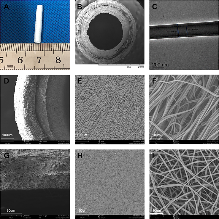 | Figure 2 The morphology of PLCL/SF/Hep scaffold. (A) The digital photograph of the whole scaffold. (B) The SEM photograph of the cross-section. (C) The TEM photograph of the shell-core structure. (D–F) The SEM photographs of the loose nano-yarn. (G–I) The SEM photographs of the tight nanofiber membrane.Abbreviations: PLCL, poly(L-lactide-co-ε-caprolactone); SF, silk fibroin; Hep, heparin. |
Hydrophobicity analysis
As shown in Figure 3, compared to the pure PLCL nanofiber membrane (a), the contact angle of the PLCL/Hep nanofiber membrane (b) was reduced, indicating the addition of heparin can increase the hydrophilicity. Meanwhile, the contact angle of the PLCL/SF/Hep nanofiber membrane (c) dropped sharply compared with the PLCL/Hep nanofiber membrane due to the addition of SF. Thus, in terms of hydrophilicity, the PLCL/SF/Hep nanofiber membrane was greater than the PLCL/Hep nanofiber membrane, which was greater than the PLCL nanofiber membrane. In addition, the contact angle of the PLCL/SF nano yarn is shown in Figure 3D.
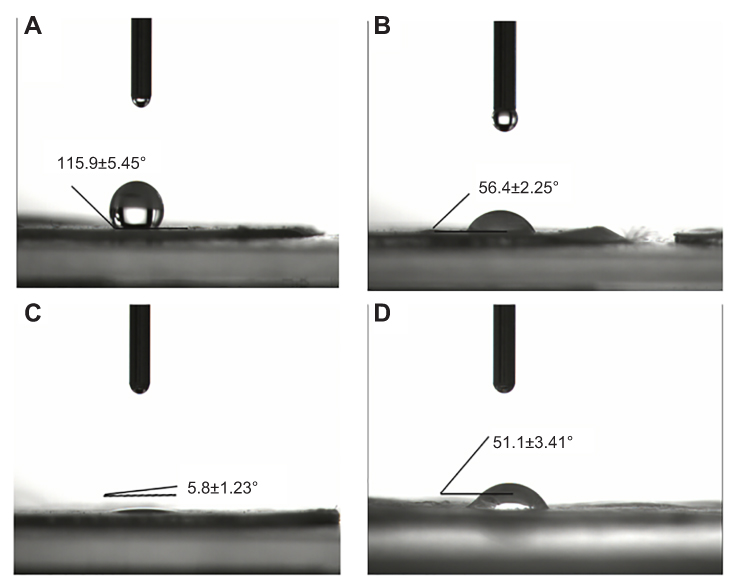 | Figure 3 The contact angle of different materials. (A) Pure PLCL nanofiber membrane, (B) PLCL/Hep nanofiber membrane, (C) PLCL/SF/Hep nanofiber membrane, and (D) PLCL/SF nano-yarn.Abbreviations: PLCL, poly(L-lactide-co-ε-caprolactone); SF, silk fibroin; Hep, heparin. |
Mechanical performance
Figure 4 demonstrates the radial and axial mechanical properties of the PLCL/SF/Hep scaffold, PLCL/Hep scaffold, and rabbit carotid artery. Compared with the rabbit carotid artery, the two synthetic scaffolds had stronger axial mechanical strength (Figure 4A) and they can achieve greater deformation (almost double). As for the radial mechanical strength, the carotid artery deformed least, while the PLCL/Hep scaffold deformed most under the same tensile stress. Two synthetic scaffolds can achieve greater deformation in the radial direction (almost double). Overall, both artificial scaffolds were suitable for application.
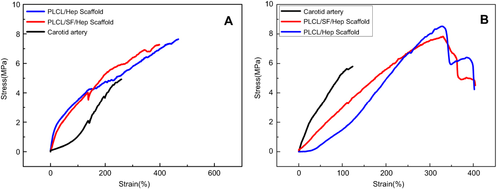 | Figure 4 The tensile test results in wet conditions of different scaffolds. (A) The axial tensile curves. (B) The radial tensile curves. |
Heparin release curves
In order to check whether heparin was properly loaded, the in vitro release assay was conducted for 15 days, and the results are shown in Figure 5. First, the amount of heparin released of PLCL/SF/Hep was greater than that of PLCL/Hep nanofiber membrane. Meanwhile, in the aqueous solution (both of PLCL/SF/Hep and PLCL/Hep), the release of heparin was found to experience two stages: the initial burst release at day 1 and the continuous release from day 2 to day 15. When exposed to PBS buffer, the heparin was immediately released by the end of the first day. After the initial burst release, sustained release could be observed as the curve showed stable ascending trend. The total amount of the released heparin was approximately 45% and 40% after 15 days. The diffusion of heparin near the fiber surface was the main factor leading to the initial burst release, while in the second stage, the mechanism of heparin release would involve: (1) heparin diffusion through the polymer fibers and release into the media; (2) the erosion and swelling of materials, as a result of which led the difference of heparin release of PLCL/SF/Hep and PLCL/Hep nanofiber membrane.
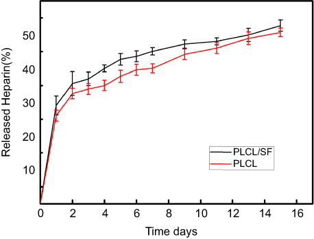 | Figure 5 Heparin release profiles of PLCL/SF (dark curve) and PLCL nanofiber membrane loading heparin (red curve).Abbreviations: PLCL, poly(L-lactide-co-ε-caprolactone); SF, silk fibroin; Hep, heparin. |
Plasma re-calcification test and platelet adhesion test
Contact with blood and materials can lead to insoluble fibrin clots, leading to thrombosis. We performed plasma re-calcification assay and platelet adhesion tests to demonstrate the material’s ability to resist thrombosis. Re-adding an appropriate amount of calcium ion to the plasma can promote the formation of insoluble fibrin clots, resulting in absorbance at 405 nm. The more fibrin clots, the higher the absorbance will be at 405 nm. As shown in Figure 6A, the time to form insoluble fiber clots in the positive control group was the shortest, and the kinetic inflection point appeared at about 25 mins. The plasma re-calcification curve of the PLCL/Hep nanofiber membrane was comparable to the positive control group. In contrast, the plasma re-calcification curve of the PLCL/SF/Hep nanofiber membranes was similar to the negative control group. There was no inflection point and the absorbance at 405 nm was very low, indicating the addition of SF increased blood compatibility and does not cause endogenous coagulation.
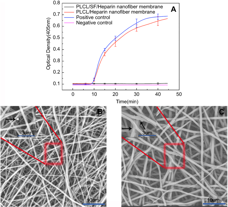 | Figure 6 The ability to resist thrombosis. (A) The plasma re-calcification curve of different materials, (B) the platelet adhesion result of PLCL/SF/Hep nanofiber membrane, and (C) the platelet adhesion result of PLCL/Hep nanofiber membrane. (The black arrow represents adherent thrombus).Abbreviations: PLCL, poly(L-lactide-co-ε-caprolactone); SF, silk fibroin; Hep, heparin. |
In addition, the platelet adhesion test can reflect the antithrombotic capacity. As shown in Figure 6, the amount of adherent platelets on PLCL/SF/Hep nanofiber membrane (b) was much less than on the PLCL/Hep nanofiber membrane (c), indicating that the addition of SF can greatly improve the blood compatibility and increase its antithrombotic capacity.
HUVECs proliferation evaluation
We used the CCK-8 method to demonstrate the proliferation of HUVECs on different materials. The higher the absorbance at 405 nm, the greater the number of cells. Figure 7A shows the proliferation of cells for 1–7 days. At day 1, there was no statistically significant difference among different materials. However, at day 4 and 7, there was a significant difference between PLCL/SF/Hep nanofiber membranes and PLCL/Hep nanofiber membranes. The above results showed that the addition of SF can improve the biocompatibility of the materials, facilitating adhesion and proliferation of the endothelial cells.
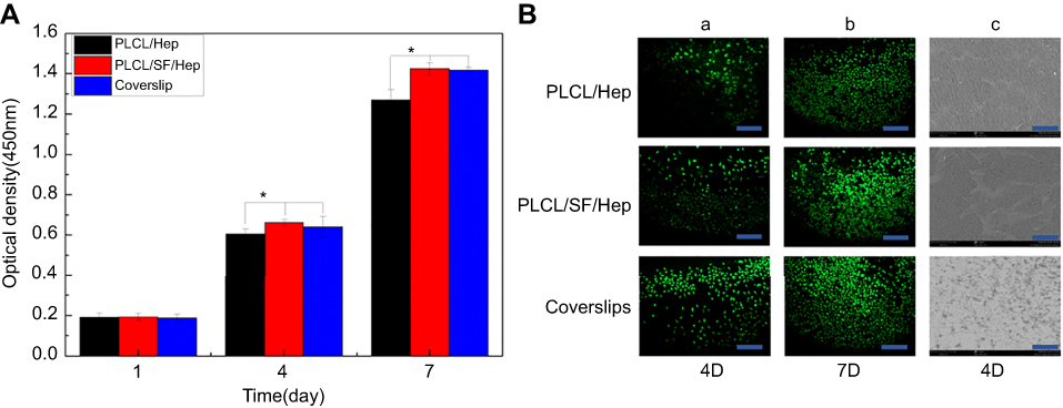 | Figure 7 HUVECs proliferation evaluation on different materials. (A) The optical density of different materials after culturing (*p<0.05), (B) a-b: Live cell staining photomicrograph of HUVECs (bar: 200 μm), and c: SEM images of HUVECs grown on different materials at day 4 (bar: 500 μm).Abbreviations: PLCL, poly(L-lactide-co-ε-caprolactone); SF, silk fibroin; Hep, heparin; HUVECs, human umbilical vein endothelial cells. |
Calcein staining results in HUVECs are shown in Figure 7Ba-b. At day 4, the endothelial cells on different materials were almost “goose-shaped”. By day 7, cell growth on the PLCL/SF/Hep nanofiber membrane had become saturated. There were few gaps between the cells, forming a cell sheet, resulting in endothelialization. By contrast, there was still some space among the endothelial cells on the PLCL/Hep nanofiber membrane. Therefore, it can be concluded that the addition of SF had greatly improved the biocompatibility of the materials. The SEM images of endothelial cells shown in Figure 6Bc also confirmed these results. In summary, endothelial cells adhered to and proliferated better on the PLCL/SF/Hep nanofiber membranes.
Orthotopic implantation and non-invasive imaging
As demonstrated in Figure 8A, there was no bleeding in the anastomosis after implantation. Furthermore, the postoperative rich vascularization on the surface confirmed the biocompatibility of the PLCL/SF/Hep scaffolds (Figure 8B). At the same time, the results of ultrasound imaging showed the PLCL/SF/Hep scaffolds retained their patency within 3 months after surgery (Figure 8C–L). However, scaffold expansion occurred at 3 months after surgery. We speculated that this may be due to the rate of tissue regeneration, which cannot match the rate of degradation of materials, resulting in insufficient late mechanical properties. Despite this, the ultrasound results still showed a good patency rate in the experimental group (PLCL/SF/Hep). In contrast, the PLCL/Hep scaffolds in the control group did not show blood flow signals at 2 weeks after surgery. The lumen was filled with high signals, which was indicative of thrombosis.
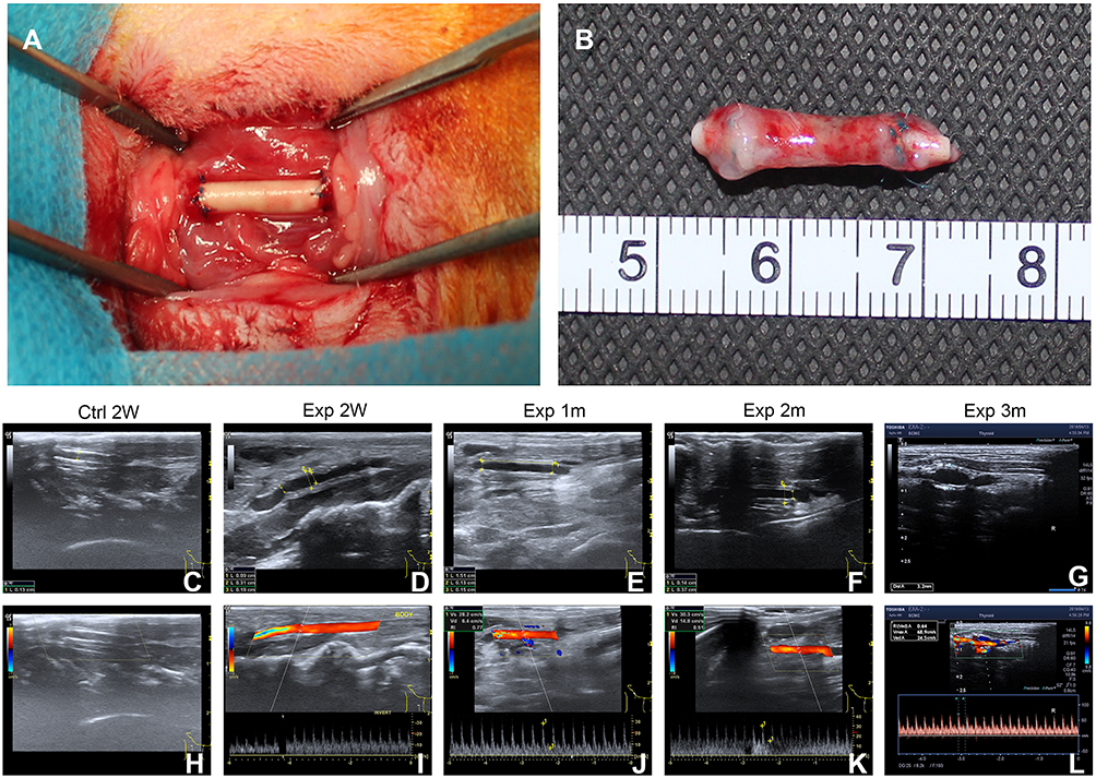 | Figure 8 The surgical procedure and ultrasound results. (A) Re-establishment of the right carotid artery, (B) the postoperative PLCL/SF/Hep scaffold, (C) B-mold ultrasound image of PLCL/Hep scaffolds at 2 weeks after surgery, (D–G) B-mold ultrasound image of PLCL/SF/Hep scaffolds at 2 weeks, and 1, 2, and 3 months after surgery, respectively, (H) Flow signal diagram of PLCL/Hep scaffolds at 2 weeks after surgery, (I–L) Flow signal diagram of PLCL/SF/Hep scaffolds at 2 weeks and 1, 2, and 3 months after surgery, respectively.Abbreviations: PLCL, poly(L-lactide-co-ε-caprolactone); SF, silk fibroin; Hep, heparin. |
Inflammation assessment
The level of blood immunoglobulin is one of the indicators for determining humoral immunity. As shown in Table 1, the IgA levels of the experimental group showed a rise compared to normal rabbits and the control group, which may be related to the addition of SF. As a heterologous protein, SF might cause a slight humoral immune response in the body. However, regarding the IgG, IgM, and total IgE, neither the experimental group nor the control group showed any fluctuations at 3 days after surgery. This suggested that SF had good biosafety and is unlikely to cause rejection.
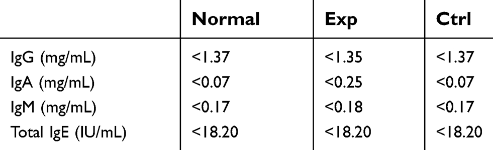 | Table 1 The level of blood immunoglobulin of different vascular scaffolds |
H&E staining and immunofluorescence staining
The histological changes of different scaffolds were further investigated by fixed section staining. As shown in Figure 9, H&E staining confirmed the PLCL/SF/Hep scaffolds retained patency and no thrombus formed within 3 months of surgery, which was similar to the native rabbit carotid artery. It is worth mentioning that at 3 months after surgery, the vascular scaffolds showed stratification, which might cause the loss of mechanics and eventually lead to lumen expansion. In contrast, the PLCL/Hep scaffolds were filled with thrombus-like tissue at 2 weeks after operation, which explained why blood flow signals could not be detected under ultrasound. The number of fibroblast cells infiltrating into the wall was increasing over time due to the porous nano yarn. Immunofluorescence staining of CD31 (an endothelial cell-specific marker) (Figure 10) and αSMA (a kind of smooth muscle cell-specific marker) (Figure 11) was also performed to detect neo-intimal changes. The CD31 staining results in the experimental group were similar to the native carotid artery. A continuous endothelial layer gradually formed within 3 months after the operation. However, there were only some disordered green fluorescence cells positive for CD31 in the control group (in fact thrombus). The α-SMA staining results of the experimental group were also similar to the native artery. A continuous smooth muscle layer was gradually formed within 3 months after the operation. In contrast, no vascular smooth muscle layer appeared in the control group due to the formation of thrombus. This result suggested that the neo-intimal formation in the experimental group was the main reason for maintaining patency. Therefore, it can be concluded that the addition of SF can specifically aid in recruiting adherent endothelial cells and smooth muscle cells to form a neo-intimal in the blood flow environment, preventing the formation of thrombus.
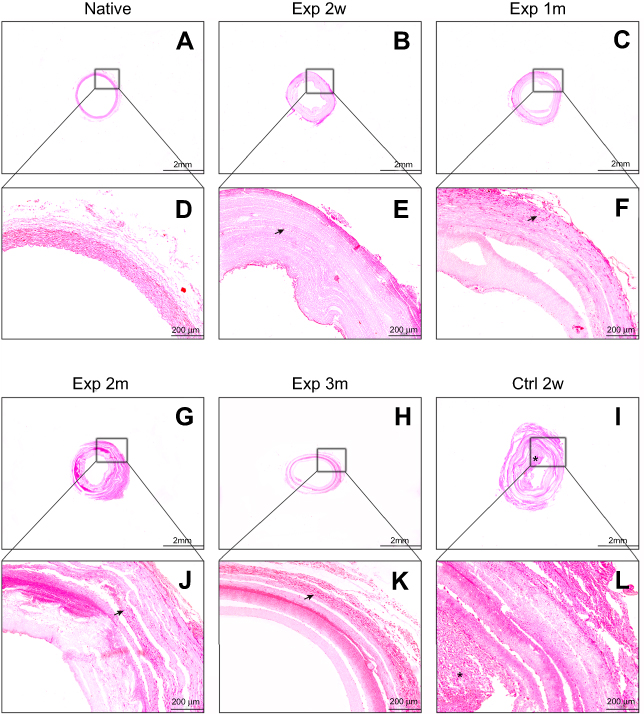 | Figure 9 The HE staining of different vascular scaffolds. (A/B/C/G/H/I) The results of rabbit carotid artery, PLCL/SF/Hep scaffolds at 2 weeks, and 1, 2, and 3 months and PLCL/Hep scaffolds at 2 weeks after surgery, respectively, bar=2 mm. (D/E/F/J/K/L) The HE staining diagrams at high magnification, bar=200 um. (Arrow represents infiltrated fibroblast cells; “*” represents thrombus).Abbreviations: PLCL, poly(L-lactide-co-ε-caprolactone); SF, silk fibroin; Hep, heparin. |
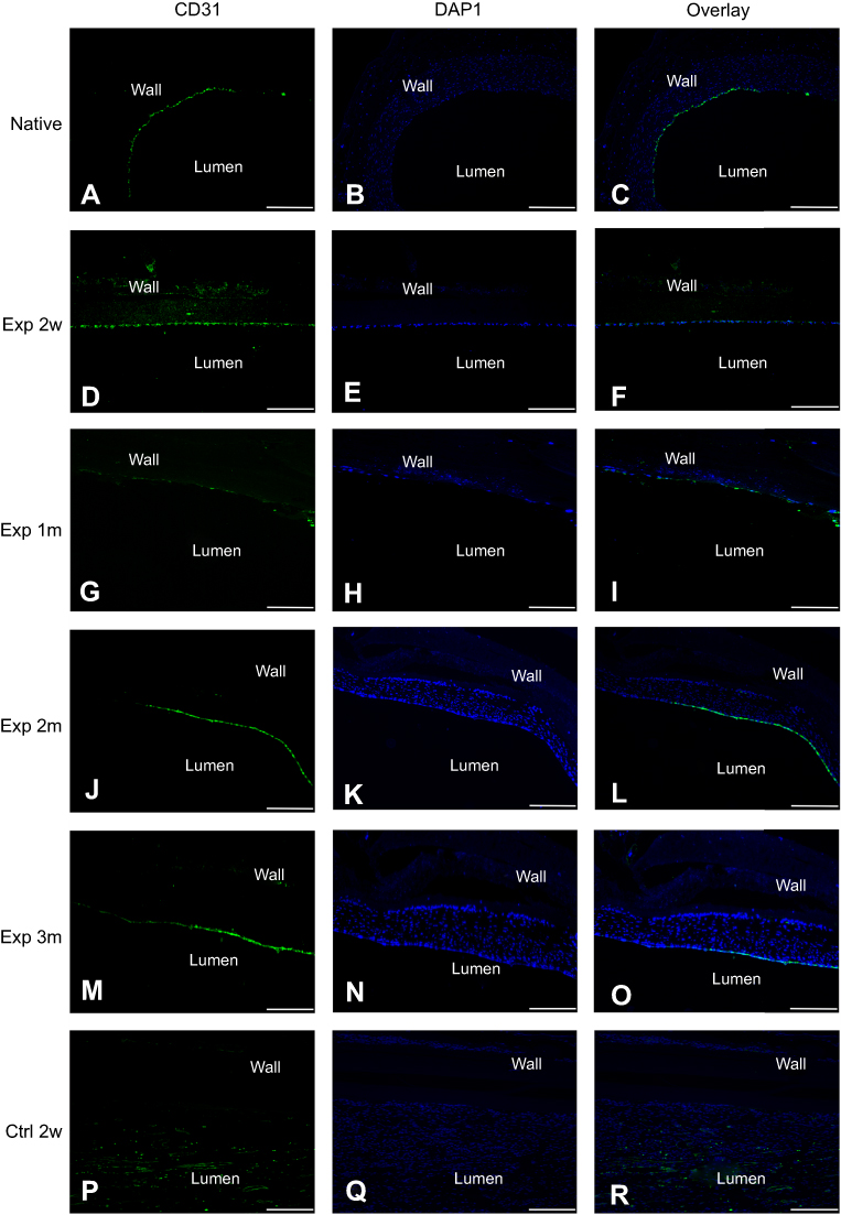 | Figure 10 The CD31 immunofluorescence staining of different vascular scaffolds. (A–C) The results of rabbit carotid artery. (D–O) The results of PLCL/SF/Hep scaffolds at 2 weeks, 1, 2, and 3 months after surgery. (P–R) The results of PLCL/Hep scaffolds at 2 weeks after surgery. All sliced samples were harvested from the middle segment. (Green: CD31+ cells; Blue: living cell nucleus; bar=500 um).Abbreviations: PLCL, poly(L-lactide-co-ε-caprolactone); SF, silk fibroin; Hep, heparin. |
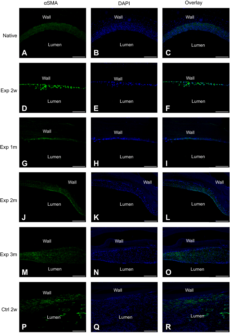 | Figure 11 The αSMA immunofluorescence staining of different vascular scaffolds. (A–C) The results of rabbit carotid artery. (D–O) The results of PLCL/SF/Hep scaffolds at 2 weeks and 1, 2, and 3 months after surgery. (P–R) The results of PLCL/Hep scaffolds at 2 weeks after surgery. All sliced samples were harvested from the middle segment. (Green: αSMA+ cells; Blue: living cell nucleus; bar=500 um).Abbreviations: PLCL, poly(L-lactide-co-ε-caprolactone); SF, silk fibroin; Hep, heparin. |
Discussion
The native vessels mainly include three layers with different functions. The adventitia is mainly responsible for maintaining the mechanical strength, while the endothelial layer and the smooth muscle layer are most related to the anti-thrombotic ability by interactive signal transmission.13,14 Therefore, it is popular to manufacture multi-layered vascular scaffolds by mimicking the geometry of natural artery, such as bi-layered or tri-layered scaffolds.10,15,16 However, limited by the respective defects in polymer and natural materials, most groups have adopted the hybrid strategy to prepare scaffold-based vessels using a combination of different materials. For example, Ju et al prepared bi-layered scaffolds based on poly(caprolactone) (PCL) and collagen,17 and Liu et al explored the possible application of a tri-layered scaffolds with an inner and outer layer based on poly(vinyl alcohol) (PVA)/chitosan and a middle layer based on poly(p-dioxanone) (PPDO).18 In addition, to achieve accomplished functional vascular remodeling after transplantation, especially endothelialization and ready proliferation of the vascular smooth muscle cells (the best anti-thrombotic drug in the body), cell inoculation or bio-active factors loading in vitro had been employed. Clay Quinta et al seeded cells to pre-culture the endothelial layer in vitro and then transplanted the scaffolds.19 Some groups have loaded endothelial cell-specific receptors, such as VEGF, RGD peptide, or other cell factors to encourage the adherence of endothelial cells.20–22 These studies have made a certain degree of progress. However, there are still many problems in the practical application, which includes complicated preparation, potential cellular immune rejection, and limited effects.
The less processing, the more advantageous it will be for application. As a natural protein, SF is widely used in regenerative medicine due to its excellent biocompatibility, such as vascular tissue regeneration,23 neural tissue regeneration,24 bone tissue regeneration25 and skin tissue regeneration.26 Compared to other protein-based biomaterials, SF is less risky in regards to infection and has a simpler purification process.27 Thus, it is safer and more economical. Apart from the aforementioned advantages, SF fibers also possess good mechanical properties. It is tougher than Kevlar, which is considered a benchmark in high-performance fiber technology. However, it is worth noting that most silks developed from SF solutions are fragile, despite the outstanding mechanical properties of native SF fibers. For example, the silk film has a dry tensile strength of about 0.02 GPa and an elongation at break of less than 2% compared to a native fiber having a tensile strength of about 0.5–0.6 GPa and an elongation at break of 10–40%.28 Gellynck et al indicated this is due to the lack of suitable secondary and hierarchical structures prepared by solution compared to native fibers.29 Therefore, increasing the mechanical strength will greatly expand the application of regenerated SF fibers. PLCL (a synthetic polymer material) also possesses high mechanical strength. However, it is hydrophobic and lacks effective cell binding sites. Therefore, although it has been approved by the FDA as a biomedical biomaterial, its practical application is limited.
In this experiment, we combined PLCL and SF to prepare a hybrid vascular scaffold. On one hand, the hydrophilicity was improved by utilizing SF. On the other hand, the superior mechanical strength of PLCL can compensate for the brittleness of the SF film, which was confirmed by hydrophobicity analysis and mechanical performance. The scaffolds were designed as a bi-layered structure with inner PLCL/SF/Hep nanofiber membrane and outer PLCL/SF nano yarn. The dense inner layer can prevent blood leakage, and the loose outer layer can increase the infiltration of fibroblasts. At the same time, there was no increase in immunoglobulin levels, except for a slight increase in IgA levels (representing a minor immune response) after the scaffolds were transplanted. This indicated that although as a heterologous protein, SF has acceptable biosafety and is unlikely to cause immune rejection. Compared to the PLCL/Hep scaffolds in the control group, the PLCL/SF/Hep scaffolds remained unobstructed and no thrombus formed within 3 months after surgery, which was confirmed by both ultrasound and H&E staining. Immunofluorescence results showed that at 2 weeks after surgery, the inner wall of the PLCL/SF/Hep scaffolds began to recruit the adherence of endothelial and smooth muscle cells. Within 3 months after surgery, a continuous and smooth functional layer (endothelial layer plus smooth muscle layer) formed gradually, which prevented the formation of thrombus.
Once native vessels are damaged, the injury site activates a variety of cellular pathways and secretes related cytokines, recruiting relevant progenitor cells30–32 in the blood or related precursor cells33–35 adjacent to the injury site. The recruited cells colonize, proliferate and differentiate, creating new endothelial and smooth muscle layers gradually in the bloodstream environment. Therefore, based on our experimental results, we have reasons to believe that due to the addition of SF, the hydrophilicity of the composite material was improved, thereby increasing relevant progenitor or precursor cells adhesion. Furthermore, under the guidance of blood flow and stress, the recruited cells differentiated into endothelial cells and smooth muscle cells, finally participating in the vascular remodeling.36
It is worth noting that although the PLCL/SF/Hep scaffolds stood out in regards to remodeling for endothelial and smooth muscle layer, some scaffolds showed expansion similar to a true aneurysm at 3 months after surgery. Limited by insufficient experimental samples, we did not perform mechanical tests after transplantation. We speculated that the rate of tissue regeneration and material degradation did not match, which lead to insufficient adventitia regeneration, finally causing the loss of mechanical strength. Although the results of H&E staining showed the number of fibroblast cells infiltrating into the wall was increasing within 3 months after surgery due to the porous structure of nano-yarn, it seemed to not be sufficient to maintain the later mechanics. The PLCL/SF/Hep scaffolds showed stratification at 3 months after surgery, which may be caused by the inconsistent swelling rate due to the different densities of the inner and outer layer.
Here, we conducted both in vitro and in vivo experiments of a bi-layered vascular scaffolds based on PLCL and SF. The scaffolds formed a neo-functional inner layer spontaneously in the blood flow environment without any additional processing and retained patency for 3 months after surgery. In the future, we will focus on solving the problem with the stratification of materials and the regeneration of the adventitia to maintain late mechanical strength.
Conclusion
In this study, we prepared a simple off-the-shelf bi-layered vascular scaffold based on PLCL/SF/Hep suitable for implantation into the carotid artery of rabbits. Compared to PLCL/Hep scaffolds, PLCL/SF/Hep scaffolds can maintain patency for 3 months after implantation. More importantly, in the absence of any selective adhesion factor, immunofluorescence results demonstrate that a continuous neo-intimal layer formed spontaneously in a flowing blood environment.
Limitation and prospect
Currently, the application of artificial vascular scaffold mainly faces the following bottlenecks: 1) The mechanical mismatch between artificial scaffold and native vessel; 2) Endothelial insufficiency leads to early thrombosis formation; 3) Smooth muscle cell hyper-proliferation causes late intimal thickening, resulting in concentric stenosis. In this experiment, while the PLCL/SF/Hep scaffolds had been retained lumen patency during the 3 months following surgery, we noticed that lumen expansion occurred at a later stage. We speculated this may be due to stratification, causing a drop in mechanics, but might also be related to poor remodeling of the adventitia, which is the most important structure responsible for the mechanical strength of the artery. In addition, nevertheless immunofluorescence staining confirmed the endothelium and smooth muscle layer formed spontaneously, the thickness of the smooth muscle layer seemed dynamically thickened as time went by. Relevant improvements for spinning methodology and material modification may help solve such problems.
Acknowledgments
This study was supported by National Natural Science Fund of China (81873923, 31470941, 31771023), National Major Research Program of China (2016YFA0201702 of 2016YFA02011700), Shanghai Science and Technology Development Fund (16CR3078B), Science and Technology Development Fund of Shanghai Pudong (PKJ2016-Y33), Collaborative Innovation Center for Translational Medicine, Shanghai Jiao Tong University School of Medicine (TM201504), and scientific research project of Ai You Foundation (2017SCMC-AY002). The authors would like to thank the Duoease Scientific Service Center for excellent language editing service and suggestions for figure revision.
Disclosure
All authors report no conflicts of interest in this work.
References
1. Zoghbi WA, Duncan T, Antman E, et al. Sustainable development goals and the future of cardiovascular health: a statement from the global cardiovascular disease taskforce. Glob Heart. 2014;9(3):273–274.
2. Tenekecioglu E, Bourantas C, Abdelghani M, et al. From drug eluting stents to bioresorbable scaffolds; to new horizons in PCI. Expert Rev Med Devices. 2016;13(3):271–286. doi:10.1586/17434440.2016.1143356
3. Dahl SLM, Kypson AP, Lawson JH, et al. Readily available tissue-engineered vascular grafts. Sci Transl Med. 2011;3(68):68ra69. doi:10.1126/scitranslmed.3001426
4. Manson RJ, Unger JM, Ali A, Gage SM, Lawson JH. Tissue-engineered vascular grafts: autologous off-the-shelf vascular access? Semin Nephrol. 2012;32(6):582–591. doi:10.1016/j.semnephrol.2012.10.010
5. Wystrychowski W, McAllister TN, Zagalski K, Dusserre N, Cierpka L, L’Heureux N. First human use of an allogeneic tissue-engineered vascular graft for hemodialysis access. J Vasc Surg. 2014;60(5):1353–1357. doi:10.1016/j.jvs.2013.08.018
6. Shannon LM, Dahl JLB, Niklason LE. Bioengineered vascular grafts- can we make them off-the-shelf? Trends Cardiovasc Med. 2011;21(3):83–89. doi:10.1016/j.tcm.2012.03.004
7. Pashneh-Tala S, MacNeil S, Claeyssens F. The tissue-engineered vascular graft-past, present, and future. Tissue Eng Part B Rev. 2016;22(1):68–100.
8. Fu W, Liu Z, Feng B, et al. Electrospun gelatin/PCL and collagen/PLCL scaffolds for vascular tissue engineering. Int J Nanomedicine. 2014;9:2335–2344. doi:10.2147/IJN.S61375
9. Zhang K, Mo X, Huang C, He C, Wang H. Electrospun scaffolds from silk fibroin and their cellular compatibility. J Biomed Mater Res A. 2010;93(3):976–983. doi:10.1002/jbm.a.32497
10. Liu H, Li X, Zhou G, Fan H, Fan Y. Electrospun sulfated silk fibroin nanofibrous scaffolds for vascular tissue engineering. Biomaterials. 2011;32(15):3784–3793. doi:10.1016/j.biomaterials.2011.02.002
11. Soffer L, Wang X, Zhang X, et al. Silk-based electrospun tubular scaffolds for tissue-engineered vascular grafts. J Biomater Sci Polym Ed. 2008;19(5):653–664. doi:10.1163/156856208784089607
12. Sampath U, Ching YC, Chuah CH, Sabariah JJ, Lin PC. Fabrication of porous materials from natural/synthetic biopolymers and their composites. Materials (Basel). 2016;9(12). doi:10.3390/ma9120991
13.
14. Wagenseil JE, Mecham RP. Vascular extracellular matrix and arterial mechanics. Physiol Rev. 2009;89(3):957–989. doi:10.1152/physrev.00041.2008
15. Dong X, Yuan X, Wang L, et al. Construction of a bilayered vascular graft with smooth internal surface for improved hemocompatibility and endothelial cell monolayer formation. Biomaterials. 2018;181:1–14. doi:10.1016/j.biomaterials.2018.07.027
16. Wilkens CA, Rivet CJ, Akentjew TL, Alverio J, Khoury M, Acevedo JP. Layer-by-layer approach for a uniformed fabrication of a cell patterned vessel-like construct. Biofabrication. 2016;9(1):015001. doi:10.1088/1758-5090/9/1/015001
17. Ju YM, Choi JS, Atala A, Yoo JJ, Lee SJ. Bilayered scaffold for engineering cellularized blood vessels. Biomaterials. 2010;31(15):4313–4321. doi:10.1016/j.biomaterials.2010.02.002
18. Liu Y, Xiang K, Chen H, Li Y, Hu Q. Composite vascular repair grafts via micro-imprinting and electrospinning. AIP Adv. 2015;5(4):041318. doi:10.1063/1.4906571
19. Clay Quinta YK, Mansonc RJ, Lawsonc JH, Dardikb A, Niklasona LE. Decellularized tissue-engineered blood vessel as an arterial conduit. PNAS. 2011;108(22):9214–9219.
20. Zhang H, Jia X, Han F, et al. Dual-delivery of VEGF and PDGF by double-layered electrospun membranes for blood vessel regeneration. Biomaterials. 2013;34(9):2202–2212. doi:10.1016/j.biomaterials.2012.12.005
21. Antonova LV, Seifalian AM, Kutikhin AG, et al. Conjugation with RGD peptides and incorporation of vascular endothelial growth factor are equally efficient for biofunctionalization of tissue-engineered vascular grafts. Int J Mol Sci. 2016;17(11). doi:10.3390/ijms17111920.
22. Li Y, Wan S, Liu G, et al. Netrin-1 promotes inflammation resolution to achieve endothelialization of small-diameter tissue engineering blood vessels by improving endothelial progenitor cells function in situ. Adv Sci (Weinh). 2017;4(12):1700278. doi:10.1002/advs.201700278
23. Aytemiz D, Sakiyama W, Suzuki Y, et al. Small-diameter silk vascular grafts (3 mm diameter) with a double-raschel knitted silk tube coated with silk fibroin sponge. Adv Healthc Mater. 2013;2(2):361–368. doi:10.1002/adhm.201200227
24. Rao J, Cheng Y, Liu Y, et al. A multi-walled silk fibroin/silk sericin nerve conduit coated with poly(lactic-co-glycolic acid) sheath for peripheral nerve regeneration. Mater Sci Eng C Mater Biol Appl. 2017;73:319–332. doi:10.1016/j.msec.2016.12.085
25. Kuboyama N, Kiba H, Arai K, et al. Silk fibroin-based scaffolds for bone regeneration. J Biomed Mater Res B Appl Biomater. 2013;101(2):295–302. doi:10.1002/jbm.b.32839
26. Çalamak S, Erdoğdu C, Özalp M, Ulubayram K. Silk fibroin based antibacterial bionanotextiles as wound dressing materials. Mater Sci Eng C. 2014;43:11–20. doi:10.1016/j.msec.2014.07.001
27. Kundu B, Rajkhowa R, Kundu SC, Wang X. Silk fibroin biomaterials for tissue regenerations. Adv Drug Deliv Rev. 2013;65(4):457–470. doi:10.1016/j.addr.2012.09.043
28. Rajkhowa R, Levin B, Redmond SL, et al. Structure and properties of biomedical films prepared from aqueous and acidic silk fibroin solutions. J Biomed Mater Res A. 2011;97(1):37–45. doi:10.1002/jbm.a.33021
29. Gellynck K, Verdonk PC, Van Nimmen E, et al. Silkworm and spider silk scaffolds for chondrocyte support. J Mater Sci Mater Med. 2008;19(11):3399–3409. doi:10.1007/s10856-008-3474-6
30. Fernandez CE, Obi-Onuoha IC, Wallace CS, Satterwhite LL, Truskey GA, Reichert WM. Late-outgrowth endothelial progenitors from patients with coronary artery disease: endothelialization of confluent stromal cell layers. Acta Biomater. 2014;10(2):893–900. doi:10.1016/j.actbio.2013.10.004
31. Hung HS, Yang YC, Lin YC, et al. Regulation of human endothelial progenitor cell maturation by polyurethane nanocomposites. Biomaterials. 2014;35(25):6810–6821. doi:10.1016/j.biomaterials.2014.04.076
32. Lan H, Wang Y, Yin T, et al. Progress and prospects of endothelial progenitor cell therapy in coronary stent implantation. J Biomed Mater Res B Appl Biomater. 2016;104(6):1237–1247. doi:10.1002/jbm.b.33398
33. Owens GK, Kumar MS, Wamhoff BR. Molecular regulation of vascular smooth muscle cell differentiation in development and disease. Physiol Rev. 2004;84(3):767–801. doi:10.1152/physrev.00041.2003
34. Gerthoffer WT. Mechanisms of vascular smooth muscle cell migration. Circ Res. 2007;100(5):607–621. doi:10.1161/01.RES.0000258492.96097.47
35. Wang G, Jacquet L, Karamariti E, Xu Q. Origin and differentiation of vascular smooth muscle cells. J Physiol. 2015;593(14):3013–3030. doi:10.1113/JP270033
36. Gong X, Liu H, Ding X, et al. Physiological pulsatile flow culture conditions to generate functional endothelium on a sulfated silk fibroin nanofibrous scaffold. Biomaterials. 2014;35(17):4782–4791. doi:10.1016/j.biomaterials.2014.02.050
 © 2019 The Author(s). This work is published and licensed by Dove Medical Press Limited. The full terms of this license are available at https://www.dovepress.com/terms.php and incorporate the Creative Commons Attribution - Non Commercial (unported, v3.0) License.
By accessing the work you hereby accept the Terms. Non-commercial uses of the work are permitted without any further permission from Dove Medical Press Limited, provided the work is properly attributed. For permission for commercial use of this work, please see paragraphs 4.2 and 5 of our Terms.
© 2019 The Author(s). This work is published and licensed by Dove Medical Press Limited. The full terms of this license are available at https://www.dovepress.com/terms.php and incorporate the Creative Commons Attribution - Non Commercial (unported, v3.0) License.
By accessing the work you hereby accept the Terms. Non-commercial uses of the work are permitted without any further permission from Dove Medical Press Limited, provided the work is properly attributed. For permission for commercial use of this work, please see paragraphs 4.2 and 5 of our Terms.