")
Back to Journals » Research Reports in Clinical Cardiology » Volume 5
Current and emerging catheter technologies for percutaneous transluminal coronary angioplasty
Authors Udaya Prashant P
Received 14 April 2014
Accepted for publication 11 June 2014
Published 10 September 2014 Volume 2014:5 Pages 213—226
DOI https://doi.org/10.2147/RRCC.S47217
Checked for plagiarism Yes
Review by Single anonymous peer review
Peer reviewer comments 6
Ponangi Udaya Prashant
CARE Hospitals, Banjara Hills, Hyderabad, India
Abstract: Appropriate guide catheter selection is a paramount requirement for successful angioplasty of complex coronary artery lesions. When choosing an appropriate guide catheter, the diameter and shape of the guide are the most important factors to be considered, and depend on the anatomy of the coronary artery and backup support required to cross the obstructive lesion. In turn, backup support of the guide catheter depends on the size and terminal shape of the guide rather than the route of intervention chosen and can be expressed mathematically. Many radial route-specific guide catheters have been developed by introducing extratertiary curves and angles to previous existing femoral guides. Backup support can be enhanced by various maneuvers and innovations like the “mother-child” technique. Computer-aided aortogram analysis can help in choosing the right catheter for anomalous coronary arteries. Newer catheter designs like increased lumen diameter ratios, total occlusion crossing support catheters, sheathless guides, and balloon-tipped guides are helping to overcome the shortcomings of antecedent guide catheters.
Keywords: guide catheters, backup support, radial angioplasty, anomalous coronary arteries, Ikari catheter
Introduction
Guide catheter selection is the most important decision point after patient selection in interventional cardiology. An experienced operator has good knowledge of the different types of catheters available and knows which one to use when. A good choice of guide catheter makes the subsequent procedure simple, without the need to resort to complicated hardware that exposes the patient to unnecessary risk. For example, an inexperienced operator wanting to do a simple right coronary artery (RCA) angioplasty by the transradial route and realizing after multiple futile attempts that the chosen guide catheter/s is unable to hook the RCA because of a slightly abnormal takeoff, can create spasm in the radial artery and any further forceful manipulation can produce an intense vasovagal reaction with potentially catastrophic consequences. When the first percutaneous coronary intervention (PCI) was performed by Andreas Gruentzig in September 1977, a guide catheter was used to provide a conduit for the delivery of interventional equipment and support for successful passage of the PCI hardware to the target site. In addition to these basic functions, guide catheters also enable pressure measurement and contrast opacification of arteries for proper assessment.
The conduit function of a guide is important and is largely dependent on the internal diameter of the guide. The backup support function is more complicated, and depends on the shape of the catheter and also its size. The inherent “passive” support provided by a guide is dependent on the physical characteristics of the guide catheter wall and the distal preformed shape of the guide. The latter influences the ability of the guide to achieve coaxial alignment with the coronary ostium, and additionally to gain support from the aortic wall or the coronary sinus. “Active” guide support is usually achieved by operator-dependent techniques, such as deep-seating the guide beyond the ostium of the vessel or by molding the catheter in the coronary sinus.
Design of guide catheters
Guiding catheters are made up of three layers (Figure 1), ie, an inner polytetrafluoroethylene layer that is slippery, a middle stainless steel braided layer, and an outer soft nylon elastomer jacket.1 The stainless steel layer stiffens the catheter to provide support for passage of the device, but makes the guide more difficult to engage than a diagnostic catheter. The outer coating provides flexibility and support to the catheter, while the middle layer gives strength, making it kink-resistant, and allows easy torquing of the catheter. The inner layer has a lubricious coating and facilitates easy passage of the PCI hardware.
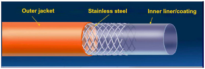 | Figure 1 Guide catheter design. |
“Thin wall” guides have combined the outer stainless steel and nylon jacket into one layer to achieve a larger inner lumen diameter for any given outer diameter (French size). These are the predominant guiding catheters currently used. In general, guide catheters have a shorter, more angulated tip and a larger internal diameter than similar-sized diagnostic catheters. The large internal diameter facilitates delivery of equipment and injection of contrast. The guide catheters have differential stiffness throughout; the proximal part is the stiffest and gradually softens towards the distal tip (Figure 2). Some guide catheters have relatively shorter and more flexible tips to decrease catheter-induced trauma, whilst other have long stiffer tips for deep seating and better passive support.2
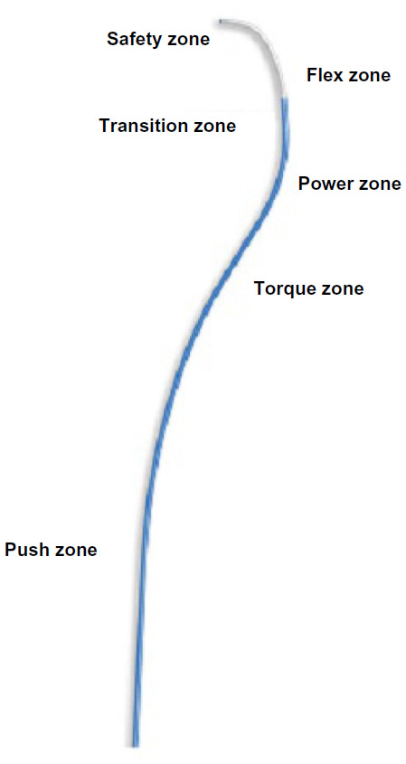 | Figure 2 Stiffness of guide catheter along its length. |
The ideal guide catheter should have the following physical properties: a stiffer body to transmit torque applied from guide hub to distal tip in a 1:1 ratio; a variable softer primary curve; wire braiding for kink resistance in response to guide torque; a soft tip to minimize ostial trauma; a large lumen (with optional radiopaque marker); and a lubricious coating for easy passage of hardware such as stents and balloons.1 These characteristics of guides are interrelated and in some instances competitive. For example, increasing the internal diameter of a guide at the expense of wall thickness may enhance the conduit function and reduce the risk of trauma, but may compromise the support function and torque control of the guide. Current guide catheter designs represent a compromise between these competing physical properties.
Guides are differentiated by the preformed shape of their terminal portion. All guides have a primary curve located closest to the tip. Some guides have additional secondary and tertiary curves located after the primary curve (Figure 3). The requirement for coaxial alignment of the guide with the coronary ostium has resulted in production of a large array of guide catheters when compared with diagnostic catheters.2
 | Figure 3 Shape of a guide showing the curves and body. |
Coaxial alignment and contrast visualization
The guide catheter should be seated with the tip parallel to the long axis of the artery (coaxial) at its origin for easy delivery of PCI hardware and better opacification of the artery with the least amount of contrast. Coaxial alignment permits safer transmission of the force needed to advance the balloon across a stenosis. This may require repositioning of the guide catheter or occasionally deep seating into the artery.3
As balloon and PCI catheters have become smaller, the size of the internal diameter of the guiding catheter has become less important for achieving adequate visualization. However, a large guide catheter lumen is critical to facilitate easy passage of double balloon systems for complex bifurcation lesions. Coaxial alignment of the guide catheter may need to be confirmed in different views, eg, the right anterior oblique view, when engaging the left main stem or RCA.
Coronary perfusion pressure
The guiding catheter measures aortic pressure during PCI with the help of a transducer connected to a side port. Pressure wave damping may occur during coronary artery engagement if there is plaque in the coronary ostium. In addition, the pressure measured through the guide catheter proximal to the stenotic area can be compared with distal pressure beyond the lesion using a pressure sensor guide wire for assessment of the hemodynamic significance of the lesion pre and post PCI, known as fractional flow reserve.
Some catheters have side holes near the tip to permit perfusion into the artery when the catheter is deeply seated and obstructing flow. Guide catheters with small side holes near the tip allow blood to enter the coronary artery when the catheter is blocked at the ostium. When the guide catheter occludes the coronary artery, there is a change in the arterial pressure waveform into more of a square wave pattern, known as “damping”. Dampening, or ventricularization, indicates significant obstruction to flow or noncoaxial orientation of the guide tip.1 The guide catheter side holes reduce ischemia when the catheter is seated in a small artery. However, side holes may lead to inadequate artery visualization due to contrast medium exiting the catheter even before entering the artery. Although side holes may provide reliable perfusion pressure, coronary flow can still be compromised during the angioplasty procedure. The guide catheter and side holes act as a “second stenosis” at the coronary ostium.4
Three features are important when selecting guide catheters, ie, the size (French) and shape of the catheter, and the backup support required. Performance of a guide catheter can be assessed on the basis of three factors: easy and rapid engagement without specific manipulation; strong backup force; and safety (ie, not causing complications such as coronary dissection). When selecting a guide catheter, one must consider the route of PCI chosen, ie, radial or femoral, use of a native vessel versus a graft vessel, left versus right coronary artery, coronary artery anomalies, tortuosity of the great vessels, and whether the procedure is an elective or primary PCI, along with the characteristics of the lesion, ie, whether it is a bifurcation lesion, a chronic total occlusion (CTO), or a calcified lesion, and finally operator preferences.
Size of guide catheter
During the early years, guide catheters were large, bulky, and difficult to handle, with higher rates of catheter-associated complications. Present-generation percutaneous transluminal coronary angioplasty balloons have become thinner and have a lower profile, and smaller sized guide catheters can be used even for complex interventions. Each 1 F reduction of guide catheter size has the added advantage of reducing the complications associated with small sized guide catheters (Figure 4).
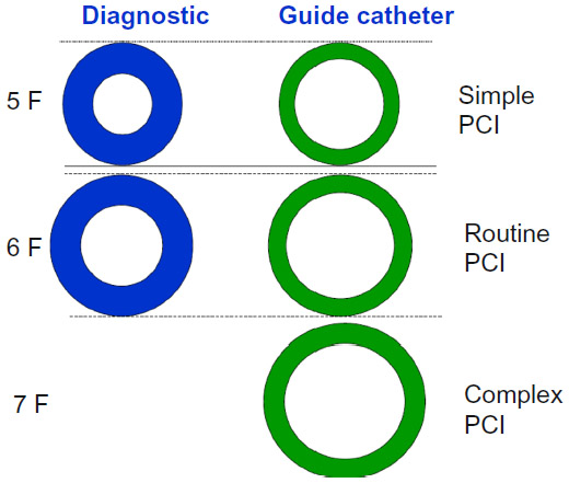 | Figure 4 Illustration showing the relative sizes of diagnostic and guide catheters and preferred cases for simple, routine, and complex PCIs. |
The majority of interventions are currently performed using 6 F and 7 F guide catheters. With the use of the radial artery as an access site, 5 F guide catheters are frequently used and with good success rates. Most uncomplicated coronary interventions can be performed using 6 F systems because these will accommodate single stents and also two balloons if they are both rapid exchange types. Current 6–7 F catheters have internal lumens that are as large as previous generation 8 F catheters.5 Small diameter guide catheters require less contrast but more backup curves for additional support.
As the size of the guide catheter increases, the backup support provided increases greatly, and a difficult PCI can often be completed successfully by simply upgrading the size of the catheter without additional maneuvers. Bifurcation stenting can be performed with 6 F guide catheters but requires staged stent deployment (modified “crush” techniques). Two over-the-wire balloons will require a 7 F system, and simultaneous two-vessel stenting mandates large sized 7 F guides. Large lumen 6 F guide catheters can accommodate rotational atherectomy catheters up to 1.75 mm in size, but larger French sizes are needed for larger burrs. Vessel characteristics, including tortuosity and calcification, may require the additional stiffness and support provided by a larger diameter guide. However, this additional stiffness increases the risk of trauma to the aorta and that of ostial coronary dissection. When compared with 6 F guides, larger sized guides have higher rates of complications, eg, an increased risk of dialysis due to the higher amount of contrast used and vascular site complications, ie, bleeding, hematoma formation, and infection.
Shape of guide catheter
The shape of the catheter chosen depends on the artery for which PCI is being planned (left or right graft vessel), whether it is normally located (high, low, or totally anomalous), the takeoff of the artery (vertical, horizontal, or downsloping), and dilatation of the aortic root (Table 1). The Judkins left/right, Amplatz left/right, and extra backup guide catheters are the most commonly used apart from customized catheters. Selection of the appropriate guide catheter is based on the type of coaxial engagement needed, factors like size of the aorta, the takeoff angle of the coronary artery from the aorta, and the degree of support needed for delivery of a specific device or vessel characteristic play a vital role in the curve shape modification (or selection). Dilated aortas require use of larger sized curves (eg, a Judkins 5 instead of a Judkins 4) especially for the left coronary artery.
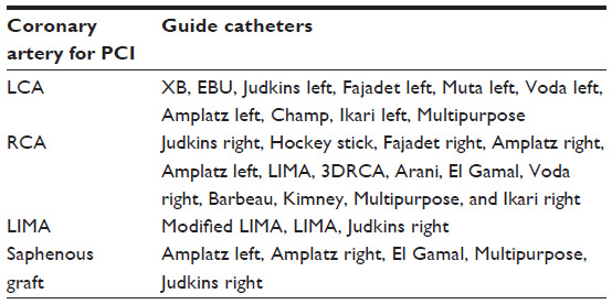 | Table 1 Guide catheters for PCI to different coronary arteries |
In the case of anomalous origin of coronary arteries, all the available standard guide catheters may fail to engage the anomalous arteries in spite of multiple attempts. Sometimes on-table modification of existing catheters by steam or hot water helps to overcome this problem.
Left coronary artery
Most of the catheters commonly used for left coronary PCI are extra backup catheters that provide adequate support. extra backup (EBU, Medtronic Inc., Minneapolis, MN, USA, or XB, Cordis Corporation, Bridgewater, NJ, USA) catheters are essentially modifications of the standard Judkins left (JL) catheter, having only one large primary curve and a stiffer tip portion. This allows the catheter to become more coaxial and provide more passive support. The area of contact is larger in extra backup catheters when compared to JL catheters. One disadvantage is that the long tipped catheters engage deeply into the target vessel during manipulation, and can produce dissections if the ostium of a vessel is diseased. Even distal left main stem plaque can produce dissections during engagement of extra backup catheters, so these devices are generally avoided and JL catheters are preferred. The newer Brite Tip® catheters (Cordis Corporation) have longer and softer tips to prevent such complications.
When doing radial angioplasty, the guide catheter is downsized by 0.5 F when compared with the femoral route. For example, while a JL 3.5 may be appropriate for the femoral route, it would be too large for the radial route and a JL 3.0 would be the right choice. In the event of complex interventions involving, eg, tortuous vessels or crossing calcified lesions, Amplatz catheters provide adequate “passive” support. For a dilated aortic root, a larger sized catheter, like a JL4, EBU4, or Voda left 4, would be used. If the ostium is higher than normal, an Amplatz left (AL)3, Voda left, or Champ catheter is preferred.6,7
Right coronary artery
A Judkins right (JR) is the first choice catheter for most RCA interventions but has no contact with the opposite wall of the aorta. This limits the support provided in complicated cases and in such situations catheters are generally switched over to an AR or AL.7
In some patients, a shepherd’s crook in the proximal course of the RCA poses problems when engaging the guide because of the upwards pointing RCA ostium. Routine catheters like a JR when used provide inadequate backup support. Left internal mammary artery, three-dimensional right coronary artery, and AL1 catheters are best suited, but the three-dimensional right coronary artery catheter is better because it is easier to manipulate and gives good support.8 Arani, El Gamal, and Voda right catheters8 have been tried, with better success rates in the event of a shepherd’s crook anomaly in the RCA.
Left internal mammary artery grafts
PCI to the left internal mammary artery is difficult via the femoral and right radial routes, but can be done easily via the left radial route with a modified or unmodified mammary catheter. PCI to the right internal mammary artery is usually attempted via the right radial, but is more difficult than anticipated because the ostium is nearly 90° with that of the catheter plane.
Saphenous grafts
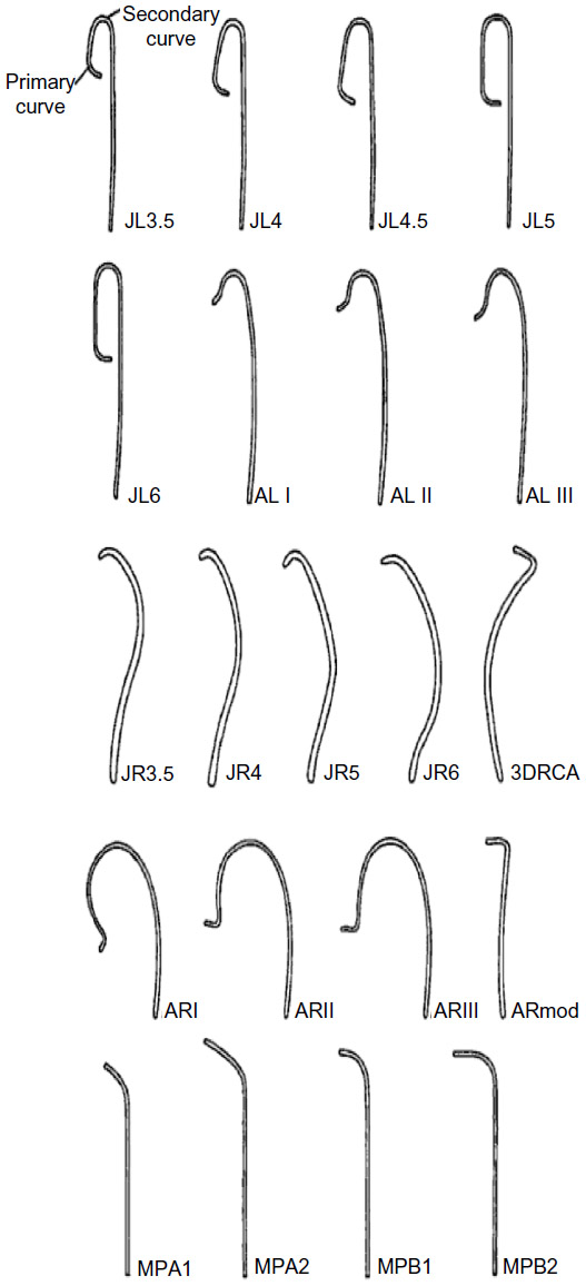
AL or hockey stick guides are used for left-sided grafts, and multipurpose, JR, or AL catheters can be used for right-sided grafts when performing PCI. Figure 5 shows the guide catheters commonly used in any standard interventional cardiology laboratory.
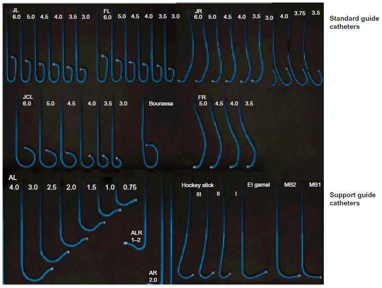 | Figure 5 Commonly used guide catheters. |
The fundamental shapes of guide catheters have become well established over time. Current improvements and innovations for guide catheters are only slight deviations from these basic shapes. There can be alterations of the physical properties of the guides, like hydrophilic inner and outer coatings, increased outer diameter to inner lumen ratio, and improved flexibility, while at the same time retaining torqueability and the support functions of the guide. Some of the newer guide catheters introduced by different companies like Adroit® (Cordis Corporation), Convey® (Boston Scientific, Marlborough, MA, USA), and Hearttrail™ II (Terumo Medical Corporation, Somerset, NJ, USA) come in the full range of standard shapes discussed in Table 1 and also with improved function.
Length of guide catheter
Although length is not thought to be a highly influential factor in selection of the guiding catheter, studies indicate positive outcomes with modification of the standard length in isolated cases.9,10 The standard length of a guiding catheter is 100 cm, although a length of >100 cm would be used for a tortuous aorta and <100 cm for distal sites (snake graft, tortuous internal mammary artery).10 Short length catheters provide ideal catheter curve for support after proper positioning, and reduces additional hardware required for opening up chronic total occlusion through retrograde approach.11
Support
Good guide support is required for optimal stent delivery, and this is the basis for selecting a guide catheter. Backup support may be defined as “the ability of the guiding catheter to remain in stable and fixed position while PCI hardware is advanced forward over a guide wire without backing off”. It has been found that the catheter size, contact area, and angle on the reverse side of the aorta are significant factors influencing the backup support of guiding catheters. An in vitro model of 6 F, 7 F, and 8 F guiding catheters concluded that the larger the size of the guiding catheter, the greater the backup force will be.12 The backup support provided by guide catheters is of two types, ie, “active” and “passive”. Passive support depends on the stiffer primary curves of the guide catheters.Guide catheters which have more passive support are usually long tipped and the shape of the catheter permits them to rest either on the valves or opposite wall of aorta. Undue manipulation of these catheters to have been avoided for fear of dissection and usually can be adjusted to for deep engagement of the desired coronary vessel. Active backup catheters have softer tips and a shape that can be altered to accommodate aortic root measurements by active manipulation with the tip position adjusted to achieve a stable coaxial position. Active support is more important while doing radial PCI when compared to femoral route because of more angulated course of guide catheters. As the size of catheter increases, the passive support provided increases and the role of active support decreases. Intermediate sized (6 F) catheters can provide both active and passive backup support. Smaller sized (5 F) catheters provide predominantly active support and larger ones (7 F, 8 F) provide more passive support,9 because larger sized catheters are less able to alter their preformed shape inside the aorta.
The XB/EBU-type guide catheters are examples of passive catheters that are utilized extensively, whereas the Ikari left (IL) and JL are active catheters. As mentioned, most of the passive support guide catheters are long tipped stiffer catheters when compared to active guide catheters.
Ikari backup force calculation with modifications
Research by Ikari et al concluded that the backup force for any guide catheter is dependent upon: size of the catheter diameter (French); the angle (theta) made by the catheter on the opposite wall of the aorta; and the catheter’s area of contact on the opposite wall of the aorta.12 These are represented in the following equation:
From principles of calculus, the maximum backup force (Fmax) is given by the second equation:
where: Fcosθ° is the vertical vector of the force F, which is the forward force required to cross the tight stenosis and as per Newton’s third law an equal and opposite reaction force is generated on the catheter, displacing it from the engaging ostium; theta (θ) is the angle between the catheter aligned along the direction of coronary ostia and opposite wall of the aorta; F is the displacing force experienced by the guide catheter during wire manipulation which is countered by the reaction force (f) from the wall of aorta; θ ° is the angle between the catheter toward the sheath and opposite wall of the aorta; and fcosθ is a downward component which counteracts the Fcosθ vector and keeps the guide catheter in a stable position without it becoming displaced while a wire or stent is being advanced forward. There is a limit to the resisting force (f) offered by the guide catheter, which mainly depends on the size (diameter, French), shape, and length of the secondary and tertiary curves. This “f” can be supplemented by pushing the guide from the sheath towards the ostium, providing additional support, but this is usually not enough. Lambda (λ) is the static friction force which prevents the guide from moving away, and this depends, among many factors, on the area of contact of the guide catheter on the opposite surface of the aorta (Figure 6).
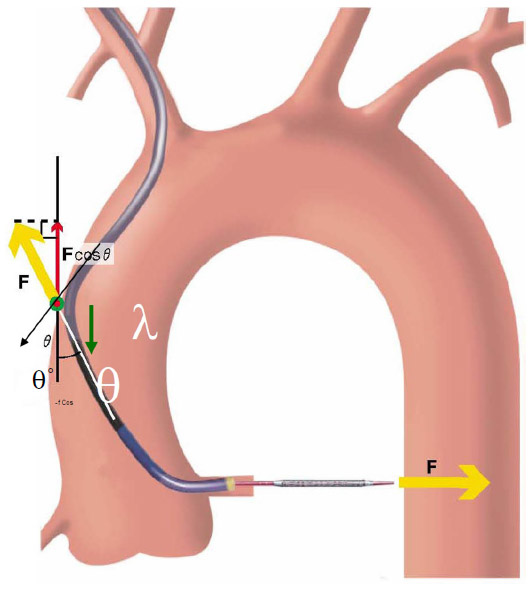 | Figure 6 Backup force calculation of a guide catheter. |
The backup force provided by any guide catheter is maximum when θ is 90°, θ° is 0°, and the area of contact is maximized. If the θ angle approaches 90°, the backup force required is minimal as cosθ approaches 0°. However, too much increase in θ results in a reduction in the area of contact between the guide and the aorta, and λ becomes smaller; hence, the overall backup support is less. Also if the flat part of the catheter in contact with opposite wall of aorta is too long then the overall backup force provided by the catheter becomes less as angle θ° becomes large.9
The somewhat rigid extra backup catheters like the EBU/Amplatz which do not allow much scope for modification of the proximal shape are the “passive” backup catheters, whereas catheters like the Judkins, Ikari, and Voda, which allow operators to change the shape of the engaging site and alter the contact area on the opposite wall of the aorta are “active” backup catheters. By changing the shape to increase the support, we are necessarily altering the θ, θ°, and λ parameters of guide catheters.
By active manipulation, catheter angles and λ of JL and Ikari catheters can be altered so that they provide increased guide catheter support during PCI. A similar technique is used with the JR while doing difficult RCA angioplasties where additional backup support is required and we framed it as “Amplatzing” the Judkins guide.
The power position differs between the Ikari and Judkins catheters. It involves increasing θ to nearly 90° without deeply engaging the coronary ostia to prevent inadvertent complications, such as left main dissection during guide catheter manipulations.12,13 Figures 7 and 8 show the power positions of right and left PCI catheters.
 | Figure 7 Power position of catheter when performing left percutaneous coronary intervention with a Judkins left catheter. |
 | Figure 8 Power position of Hockey stick catheter while performing a difficult right coronary artery angioplasty (distal total occlusion) and straightening of the right coronary artery with deep inspiration. |
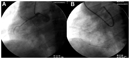
Another technique for increasing guide support involves use of the “mother-child” system (Figure 9). A mother-child innovative system is a newer advancement for enhancing the backup support of 6 F guide catheters without deeper intubation of the original guide catheters. The smaller inner 5 F tube penetrates deeply and provides greater backup support with less risk of complications such as dissections.6 Takahashi et al first described the five-in-six mother-child system in which a 5 F, 120 cm long smaller sized catheter was inserted into a 6 F, 100 cm long guide catheter.14 It was later realized that a four-in-six system was better than a five-in-six system because it provided superior track-ability and stent delivery even in tortuous arteries.15 In vitro experimental models have demonstrated that the 5 F mother-child system can generate strong backup support exceeding that of an 8 F guiding catheter whereas backup support generated by a 4 F catheter does not exceed that of a 7 F catheter.16 The mechanism of enhanced support of “child” catheters is changes the shape of “mother” catheter so that support from the contralateral aortic wall is obtained and deep intubation of the coronary is possible without producing complications (Figure 9A).
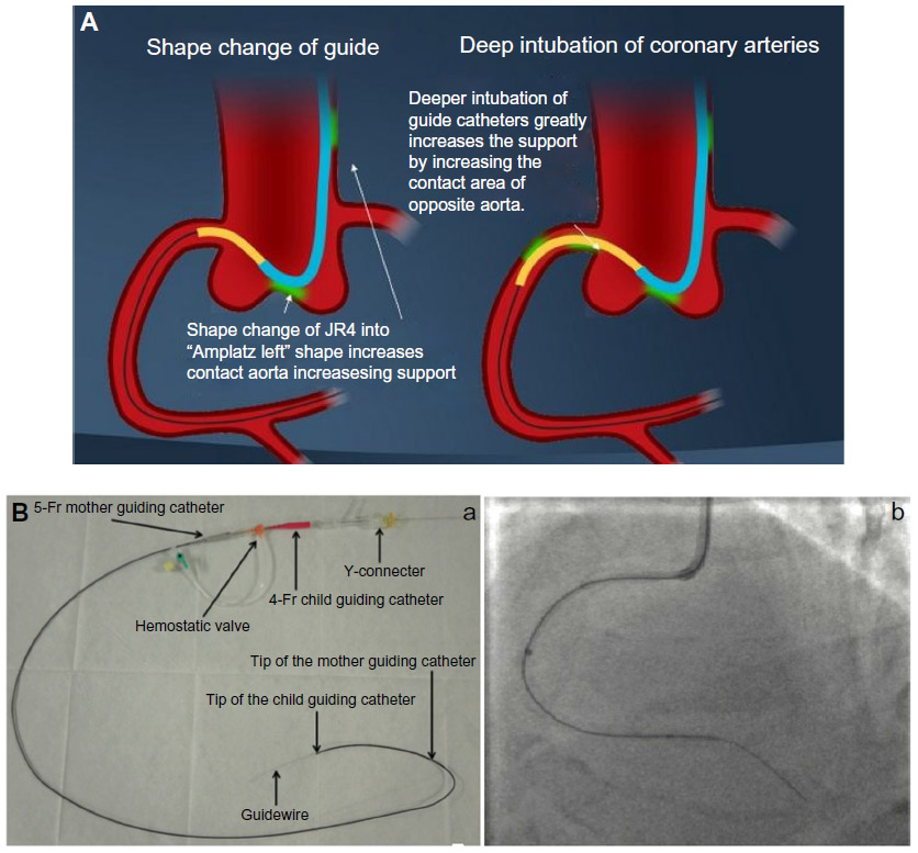 | Figure 9 Extra backup support by using “mother-child” catheters concept. |
Novel stent delivery systems are proving to be more effective in challenging deployment situations. The Kiwami® ST01 stent delivery system, newly developed 4 F straight catheter with mother-child method proved to be feasible, safer, and effective in cases where stent delivery is difficult by the conventional method. It has been deployed when the conventional method was challenging because of severe calcification, intense tortuosity, poor backup support for the guide catheter, and trapping of the stent proximal to the target lesion.16
The GuideLiner® catheter (Vascular Solutions Inc., Maple Grove, MN, US; Figure 9B) is based on the mother-child concept, with a 4 F child catheter intended to provide the extra support needed for balloon or stent delivery. It can be placed over an exchange length (300 cm) or 180 cm guide wire because it is a rapid exchange 145 cm device with a stainless steel shaft and a 20 cm single lumen catheter. Usually, it has been used as a “bail-out” device if a stent cannot cross the lesion. As the device is a guide extension, it selectively intubates the coronary artery. Although the GuideLiner catheter has been found to be useful in difficult PCI, one must be cautious when advancing this catheter into a coronary artery. There is an inherent risk of plaque disruption, which could lead to dissection and abrupt closure of the artery.
Kinking of the guide catheter during engagement of the coronary ostium can be avoided by either deep inspiration or leaving the J wire within the catheter to enhance torqueability. Although deep inspiration appears relatively simple, it is probably the most important maneuver in transradial angioplasty. Deep inspiration straightens many of the loops and curves along the catheter course and helps in both cannulating the coronary ostia and enhancing guide catheter support.
In summary, guide support for any catheter can be enhanced by:
- using larger French guides, but complications are increased
- attaining coaxial alignment with the coronary ostium
- maneuvers like deep inspiration, which reduces vessel tortuosity and helps in forward movement of guide wires, balloons, and stents
- deep throating or seating of guide catheters into the target coronary artery (Figure 10)
- Changing the guide catheter to Amplatz guide catheter or "Amplatzing" of the guide catheter, ie changing the shape of original guide to "Amplatz"-like guide catheter by active manipulation (Figures 11 and 12)
- Using a telescopic guide catheter system whereby a peripheral long sheath is advanced nearer to guide the catheter for enhanced support
- altering the θ, θ′, and λ parameters of the guide catheter by “active” manipulation in the coronary sinus
- adopting the mother-child technique with another lesser diameter catheter
- use of a “buddy” wire
- using extra support wires
- forward force applied at the starting point of guide catheter outside the sheath while crossing tight stenosis increases f
- using an "anchoring" technique, whereby on a second guide wire a small balloon is inflated in a side branch or distal vessel to give enhanced support for primary wire manipulation.
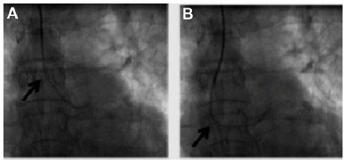
 | Figure 10 Deep seating of a Judkins right guide catheter to deliver a stent into the distal right coronary artery. |
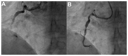
 | Figure 11 XB catheter for left anterior descending artery changed to an Amplatz left 2 catheter for proper support of percutaneous coronary intervention to the obtuse marginal artery. |
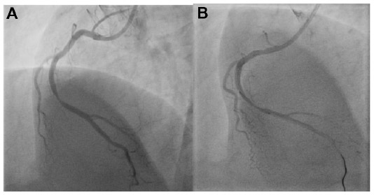
 | Figure 12 Poor support provided by a Judkins right changed to an Amplatz I with buddy wire support percutaneous coronary intervention to a total occlusion of the mid right coronary artery. |
Another useful concept worth highlighting is the increased guide support required after stenting a vessel. The guide catheter that helped in deploying the stent becomes inadequate for subsequent passing of a balloon across the deployed stent. The exact mechanism for this not well understood. Figure 13 shows how a JL guide provides enough backup support for an intravascular ultrasound Atlantis™ SR Pro catheter (Boston Scientific) to cross a tight left main ostium, but post stenting, the intravascular ultrasound catheter could not be negotiated due to inadequate guide support.
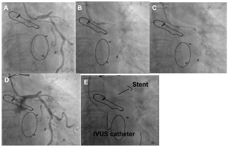 | Figure 13 Inadequate support provided by a Judkins left guide catheter for an IVUS catheter post stenting of a left main artery. |
Radial versus femoral approach
Transradial intervention has several advantages when compared with transfemoral intervention. The transradial route is more convenient for patients because the period of immobilization is less, the risk of bleeding is lower, and the overall hospital stay is shorter. However, transradial intervention has not been widely performed because of the presumed weak backup support provided by regular guide catheters. This is due to an angle between the subclavian and brachiocephalic artery that prevents the guide catheter from sitting snugly on the opposite wall of the aorta.17 The radial route has a tortuous course, especially in the elderly, and it is difficult to push forward and manipulate to the desired location. Also, catheters larger than 6 F cannot be used, which limits the complexity of the procedures done.17
From the above observations, it is clear that the support provided by catheters does not depend on the route of PCI chosen, but on guide parameters like θ, θ°, and λ, and it is a misconception that the radial route offers less support for difficult PCI.13 The guide catheters designed for the femoral approach with additional manipulation can also be utilized for transradial PCI. Even in radial PCI for the left coronary system, extra backup (EBU/XB) is the guiding catheter commonly used throughout the world, and the JR4 is the first-line catheter chosen for the RCA.18
Ikari guide catheters
The IL catheter was developed for a right upper limb approach, and is actually a modified Judkins catheter. The JL catheter easily loses engagement when the device is advanced into a tight lesion. The IL catheter has three modifications from the JL: a shorter length between the third and fourth angles; a longer length between the first and second angles; and a new first angle is added to fit the brachiocephalic artery (Figure 14).19 As a result of the above modifications, the backup force of the IL is stronger than that of the JL. The extra tertiary curve introduced on account of the brachiocephalic angle of aorta makes it easier to engage the left coronary artery.
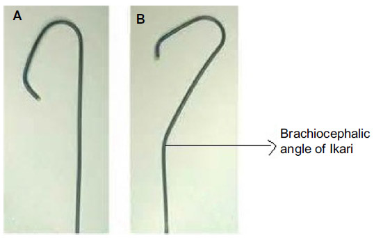 | Figure 14 Comparison between the Ikari catheter and the Judkins left catheter. |
Other dedicated radial catheters include the Barbeau and Kimney catheters.6 The Barbeau is basically a modified multipurpose catheter with an additional 135° curve at the tip to assist cannulation. The Barbeau has a softer terminal portion, and with manipulation allows the guide to take the shape of an Amplatz catheter and enables deeper coronary intubation. The Kimney catheter has a 45° primary curve with a secondary curve of 90°, which helps to provide a high degree of passive backup support.
Guide catheter selection in anomalous arteries
Anomalous coronary arteries can be classified based on:
- an abnormal position of the ostium within the sinus which can be high takeoff (>1.5 cm from aortic valves), low takeoff (<1 cm from valves), and either anterior (common) or posterior displacement of the ostium at the normal level
- abnormal angle of origin, ie, horizontal, upward, or downward
- arising from different sinuses than the normal origin. Ex RCA arising from posterior sinus or left sinus.
Engaging anomalous coronary arteries is a difficult task when using guide catheters designed for normal coronary anatomy. The ostium of an anomalous coronary artery is usually juxtacommissural, and the initial course of the anomalous artery is parallel to the aortic wall with abnormal takeoff. Due to the unusual anatomy, it is difficult to obtain coaxiality of guiding catheters. The two main obstacles to successful angioplasty of anomalous arteries are delayed recognition of the abnormal origin and technical difficulty in cannulating these arteries with conventional catheters, leading to longer procedure times and lower PCI success rates.
Coaxiality and a stable position between the proximal segment and aorta are achieved only when a suitable catheter is used. Rahman et al devised a novel catheter selection approach based on a patient’s imaging data with appropriate curve length and angles.20 This method includes segmentation of the aorta and both arteries by magnetic resonance imaging, computed tomography angiography, or conventional angiography images; computing the coronary artery curve angle, the distance of the ostium from the aortic valves, and the aortic diameter near the ostium; and identifying a suitable catheter of appropriate dimensions that fits closest to the patient’s arterial geometry.
In most cases, advanced computer-aided image processing and data analyzing software are utilized. Centerline (thin) images are created from the segmented images using the binary thinning image filter. Parameters measured include the coronary artery curve angle, the perpendicular distance of the ostium from the aortic valves, and the diameter of the aorta near the ostium. Important equivalent guide catheter measurements are: the tip angle of the catheter, catheter curve two depths, and catheter curve two widths,21 as shown in Figure 15. Unlike the traditional labeling system for guide catheters, eg, as JL3, JL3.5, and JL4, we propose to identify guide catheters by the above parameters, eg, JL 70°, 3, and 4, where the first number denotes the tip angle of the catheter, the second number denotes the catheter curve to depth, and the third denotes the catheter curve width. When guide catheter measurements match with computed aortic root measurements, they are closest to the patient’s arterial geometry and have a high probability of engaging successfully. If many catheters can fit the patient’s aortic root geometry and maximum support is required, the catheter having the most favorable θ, θ′, and λ parameters should be chosen.
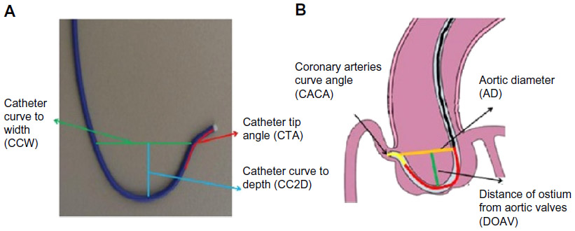 | Figure 15 Optimum catheter selection by matching aortic sinus measurements with guide catheters available on the shelf in the catheterization laboratory. |
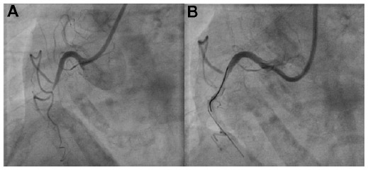
We have reported a case in which a “modified Amplatz I” guide catheter was used to perform PCI to an anomalous RCA arising posteriorly from the left sinus and having a mid segment CTO (Figure 16). The modified catheter, based on the patient’s angiographic measurements, provided maximum support for wire and balloon crossing of the CTO.22 This technique avoids testing of many catheters during catheterization. Using this method, the interventionist can get an approximate estimate of the optimal catheter for a particular patient before starting the procedure, thereby saving a lot of procedural time. In the future, this method could also be used for selection of an appropriate catheter for patients with anomalous arteries and one that would provide maximum support for crossing difficult CTOs. The success rate of CTO crossing can be increased using this method instead of opting for more complicated techniques, such as the double anchoring balloon procedure via the antegrade route, a retrograde technique with balloon-on-a-wire system, the mother-child technique, and penetration catheters, as described earlier in case reports.22
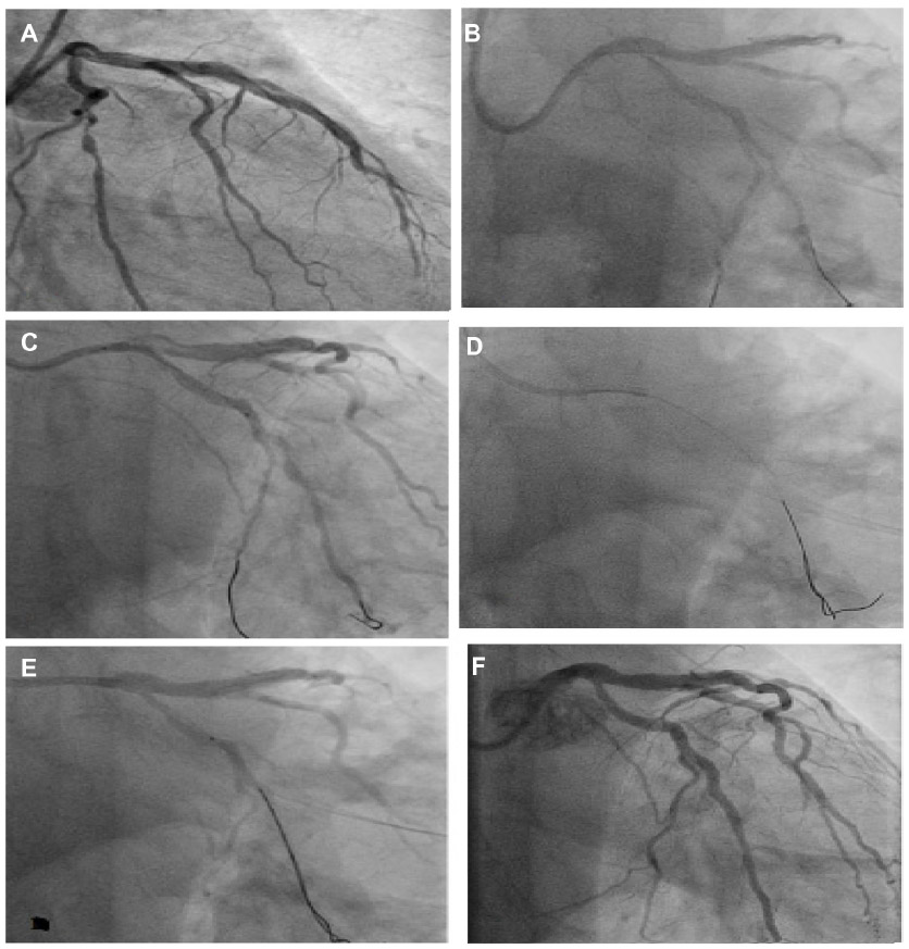
 | Figure 16 Angioplasty of anomalous right coronary artery with a chronic total occlusion using a modified Amplatz left 1 catheter with balloon support over a Whisper wire. |
Although newer techniques for guide catheter selection have been described, many operators simply rely on their intuition and past experience for difficult coronary interventions. In our experience, of all the catheters described, a correctly sized Amplatz guide catheter has been a “life saver” in many circumstances, including PCI involving difficult right saphenous grafts and anomalous arteries. But the Amplatz catheter having one of the strongest backup support capabilities is not chosen by many due to wrong assumptions of an increased risk of ostial dissections by the guide catheter. The Amplatz catheter has a bad reputation among interventionists, especially in beginners, because the previous generation catheters had hard tips and large diameters, making them prone to frequent complications. The current soft tips and small flexible, Amplatz-shaped catheters are much safer than previous catheters.23
In summary, the ability to select an appropriate guide catheter does not come from exhaustive reading alone, and nothing can replace appropriate training and the experience of performing a large number of cases. Only repeated attempts in a wide range of cases coupled with continuous practice enables the operator to choose the correct guiding catheters in difficult situations.23
Catheters in special circumstances
Guide catheters for CTO
These are divided into CTO support catheters and CTO crossing devices. CTO support catheters utilize the previously discussed mother-child technique. Some examples not discussed earlier are the CXI® (Cook Medical, Bloomington, IN, USA), Quick-Cross® (Spectranetics, Colorado Springs, CO, USA), TrailBlazer™ (Covidien Ltd, Dublin, Ireland), Gopher (Vascular Solutions Inc., Minneapolis, MN, USA). CTO crossing devices include the CrossBoss® (Boston Scientific), Crosser® (Bard Peripheral Vascular Inc., Tempe, AZ, USA), Frontrunner® (Cordis Corporation), Laser® (Spectranetics), TruePath® (Boston Scientific) Wildcat® (Avinger, Redwood City, CA, USA), and Viance® (Covidien). Over the wire or even short Monorail™ (Boston Scientific) balloons can give some support to cross tortuous or significantly stenotic lesions. The Crosair® (Asahi Intecc Co, Ltd, Burlington, MA, USA) is unique in that it is a combination of both CTO support and crossing catheters.
The CrossBoss along with the StringRay® balloon catheter and wire (Boston Scientific) are also useful tools for CTO crossing. The Frontrunner CTO catheter uses blunt microdissection with the help of actuating jaws on its tip to make a channel through the total occlusion.
Sheathless guide catheters
Sheathless guide catheters are a newer innovation to overcome the size limitations of radial guide catheters. Using a traditional sheath system, a maximum catheter size of only 6 F is possible because of the small size of the radial artery. The outer diameter of a standard radial sheath is approximately 1.5 F to 2 F sizes larger than the maximum size of the guide catheter which it will accommodate. Hence, if we can avoid using sheaths, larger sized guide catheters (7 F) can be effectively utilized, making it possible to undertake complex procedures like bifurcation stenting and other PCI procedures via the radial route.24
Balloon guide catheters
The Cello™ (Covidien) and Merci™ (Concentric Medical, Mountain View, CA, USA) balloon tipped guide catheters can be introduced for acute myocardial infarction PCI where the distal silicone balloon occludes the flow and helps in thrombus extraction. These devices are intended to be used in conjunction with thrombosuction or a mechanical thrombectomy device. The 10 mm × 10 mm silicone balloon at the tip of the guide provides temporary vascular occlusion during clot retrieval and in other angiographic procedures.
Conclusion
Guide catheter selection is the most important step when performing PCI. It is based on correct scientific understanding of the different guides available, the patient’s anatomy, and PCI route chosen. There are many techniques to enhance guide support, and selection of the best guide catheter avoids unnecessarily complex procedures with reduced procedural risk to patients.
Acknowledgments
The author is grateful to Drs P Venkata Satyanarayana (CARE Vizag) and B Soma Raju (CARE group of hospitals), and to Drs Raghava Raju, Rajeev Menon, Anuj Kapadia, Krishna Mohan, and Dandu Kavitha for helping in the preparation of this paper.
Disclosure
The author reports no conflict of interest in this work.
References
Ali R, Greenbaum AB, Kugelmass AD. A review of available angioplasty guiding catheters, wires and balloons – making the right choice. Interventional Cardiology. 2012;7(2):100–103. | |
Kern MJ. SCAI Interventional Cardiology Board Review Book. Baltimore, MD, USA: Lippincott Williams & Wilkins; 2006. | |
Kern MJ. Cardiac Catheterization Handbook. 5th ed. Philadelphia, MA, USA: Elsevier Health Sciences; 2011. | |
De Bruyne B, Stockbroeckx J, Demoor D, et al. Role of side holes in guide catheters: observations on coronary pressure and flow. Cathet Cardiovasc Diagn. 1994;33:145–152. | |
Grossman PM, Gurm HS, McNamara R, et al. Percutaneous coronary intervention complications and guide catheter size. Bigger is not better. JACC Cardiovasc Interv. 2009;2:636–644. | |
MacHaalany J, Abdelaal E, Bertrand OF. Guide catheter selection for transradial PCI. Cardiac Interventions Today. 2013. Available from: http://citoday.com/2013/08/guide-catheter-selection-for-transradial-pci. Accessed May 26, 2014. | |
Mishra S, Bahl VK. Curriculum in Cath. Lab: Coronary hardware – Part I. The choice of guiding catheter. Indian Heart J. 2009;61:80–88. | |
Grossman DE, Tuzcu EM, Simpfendorfer C, et al. Percutaneous transluminal angioplasty for shepard’s crook right coronary artery stenosis. Cathet Cardiovasc Diagn. 1989;15:189–191. | |
Ayres M. Directional coronary atherectomy in a distal right coronary lesion using a shorter standard guide catheter. Cathet Cardiovasc Diagn. 1993;29:44–46. | |
Buszman P. Optimal choice of guiding catheter and guide wire. Presented at the Eleventh Congress in New Frontiers in Interventional Cardiology, Krakow, Poland, December 1–4, 2010. | |
Joyal D, Thompson CA, Grantham J, Buller CH, Rinfret S. The retrograde technique for recanalization of chronic total occlusions: a step-by-step approach. JACC Cardiovasc Interv. 2012;5:1–11. | |
Ikari Y, Nagaoka M, Kim JY, et al. The physics of guiding catheters for the left coronary artery in transfemoral and transradial interventions. J Invasive Cardiol. 2005;17:636–641. | |
Ikari Y, Masuda N, Matsukage T. Backup force of guiding catheters for the right coronary artery in transfemoral and transradial interventions. J Invasive Cardiol. 2009;21:570–574. | |
Takahashi S, Saito S, Tanaka S, et al. New method to increase a backup support of a 6 French guiding coronary catheter. Catheter Cardiovasc Interv. 2004;63:452–456. | |
Okamura N, Takeshita S, Saito S. Transradial coronary intervention using a four-French child catheter through a six-French guiding catheter. Int J Cardiol. 2011;151:e93–e95. | |
Takeshita S, Shishido J, Sugitatsu K, et al. In vitro and human studies of a 4F double-coaxial technique (“mother-child” configuration) to facilitate stent implantation in resistant coronary vessels. Circ Cardiovasc Interv. 2011;4:155–161. | |
Tatel T, Sanjay Shah S, Pancholy S. Choosing catheter shapes for radial PCI. Cardiac Interventions Today; 2012. Available from: http://citoday.com/2012/06/choosing-catheter-shapes-for-radial-pci. Accessed May 26, 2014. | |
Ikari Y, Ochiai M, Hangaishi M, et al. Novel guide catheter for left coronary intervention via a right upper limb approach. Cathet Cardiovasc Diagn. 1998;44:244–247. | |
Amoroso G, Laarman GJ, Kiemeneij F. Overview of the transradial approach in percutaneous coronary intervention. J Cardiovasc Med. 2007;8:230–237. | |
Rahman S, Wesarg S, Voelker W. Patient specific optimal catheter selection for right coronary artery. Presented at the 2011 SPIE Medical Imaging Conference, February 12–17, 2011, Orlando, FL, USA. | |
Rauf U. Optimal catheter selection for anomalous right coronary arteries. Dissertation MEE10:115. Kaiserslautern, Germany: Blekinge Institute of Technology; 2011. | |
Prashant PU. Successful angioplasty of anomalous coronary arteries with total occlusions. J Invasive Cardiol. 2012;24:E228–E232. | |
Meier B. The guiding catheter: the most underrated asset to coronary angioplasty. J Invasive Cardiol. 2005;17:642–643. | |
Sciahbasi A, Mancone M, Cortese B, et al. Transradial percutaneous coronary interventions using sheathless guiding catheters: a multicenter registry. J Interv Cardiol. 2011;24:407–412. |
 © 2014 The Author(s). This work is published and licensed by Dove Medical Press Limited. The full terms of this license are available at https://www.dovepress.com/terms.php and incorporate the Creative Commons Attribution - Non Commercial (unported, v3.0) License.
By accessing the work you hereby accept the Terms. Non-commercial uses of the work are permitted without any further permission from Dove Medical Press Limited, provided the work is properly attributed. For permission for commercial use of this work, please see paragraphs 4.2 and 5 of our Terms.
© 2014 The Author(s). This work is published and licensed by Dove Medical Press Limited. The full terms of this license are available at https://www.dovepress.com/terms.php and incorporate the Creative Commons Attribution - Non Commercial (unported, v3.0) License.
By accessing the work you hereby accept the Terms. Non-commercial uses of the work are permitted without any further permission from Dove Medical Press Limited, provided the work is properly attributed. For permission for commercial use of this work, please see paragraphs 4.2 and 5 of our Terms.